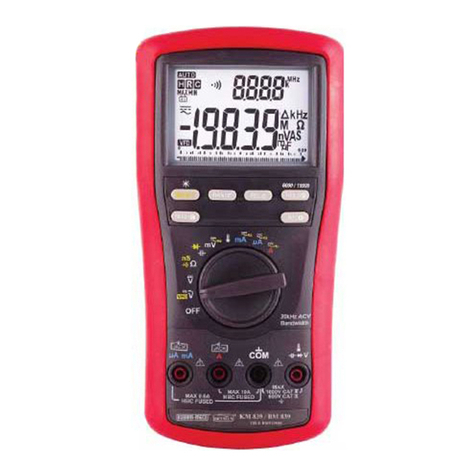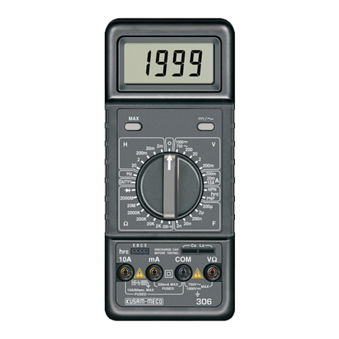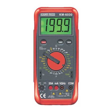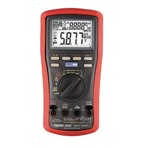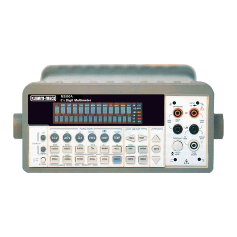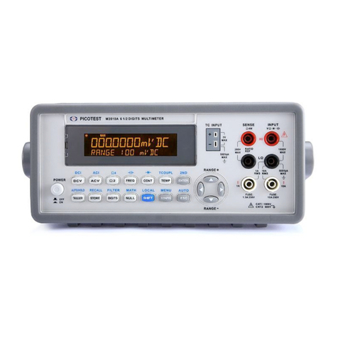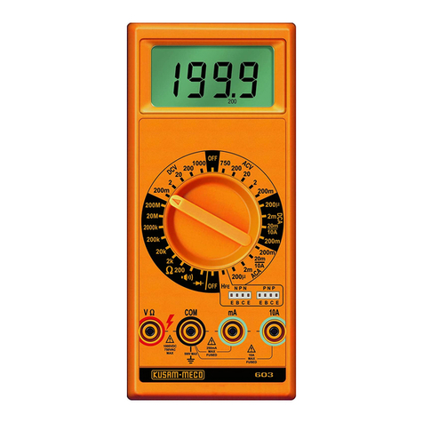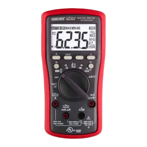
All Specifications are subject to change without prior notice.
Common Data/chhaya/my documents/chhaya/backup/catlog/New catlog/2020/5040.cdr
3-4/5 DIGIT 5000 COUNTS DIGITAL MULTIMETER WITH
ANALOG BAR GRAPH & RS-232 COMPUTER INTERFACE
Model - 5040
SPECIAL FEATURES :
˜ Basic DC Voltage Accuracy : 0.08%
˜ 50ms record MAX-MIN readings at fast 20/second
measurement mode
˜ Data Hold & Range- Hold
˜ Backlighted Display
˜ Autoranging
˜ MAX-MIN readings
˜ Fire retarded casing.
GENERAL SPECIFICATIONS
í Sensing : AC True RMS
í Display : 3-4/5 digits 5000 counts LCD display
í Update Rate : Fast data : 5 / second nominal;
52 Segment Bar-graph : 60 per second nominal.
í Operating Temperature : 0°C to 45°C
í Relative Humidity : Maximum 80% R.H. for Temperature upto 31°C
decreasing linearly to 50% R.H. at 45°C
í Storage Temperature : -20°C to 60°C, 80% R.H. (With battery removed)
í Pollution degree : 2
í Altitude : Operating below 2000m
í Temperature Coefficient : Nominal 0.15 x (specified accuracy) / °C
@ (0°C ~ 18°C or 28°C ~ 45°C), or otherwise specified.
í Power Consumption : 4.3mA typical
í Low Battery : Below approx. 7V
í APO Timing : Idle for 17 minutes.
í APO Consumption : 50mA typical
í Power Supply : Single 9V battery.
í Dimension : Approx.186(L)mm x 87(W)mm x 35.5(H)mm; 198(L)mm x 97(W)mm x 55(H)mm with holster
í Weight : Approx.340gm, Approx. 430gm with holster.
˜ Diode & Continuity Test
TM
˜ Audible & Visible BeepJack Input warning against
improper plug in.
˜ Relative-Zero offset mode
˜ Auto power off
˜ PC Interface (BRUA-85Xa) (Optional)
˜ OPTIONAL ACCESSORIES :
BRUA-85Xa PC interface Kit (BC-85Xa RS232 optical adapter cable+ Software CD + BUA-2303 USB-to-Serial adaptor)
Current Clamp CA300, Current Clamp Adaptor CA500, CA1000, CA2000, High Voltage Probe PD-28
SAFETY
˜ Safety : Double insulation per IEC / UL / EN61010-1 2nd Ed., 3.0, IEC / EN61010-2-030 Ed. 1.0, IEC / EN61010-2-033 Ed. 1.0, IEC / UL / EN61010-031
Ed. 1.1 & CAN / CSA-C22.2 No.61010-1-12 Ed. 3.0 to CAT III 1000V AC & DC and CAT IV 600V AC & DC.
˜ E. M. C. : Meets EN61326-1:2013
In an RF field of 3V/m :
Capacitance function is not specified.
Other function ranges : Total Accuracy = Specified Accuracy + 100 digits
Performance above 3V/m is not specified.
˜ Transient Protection : 8kV lightning surge (1.2/50ms)
˜ Terminals (to COM) Measurement Category :
V / A / mAmA : CAT III 1000 Volts AC & DC, and CAT IV 600 Volts AC & DC.
˜ Overload Protections :
mA & mA : 0.44A/1000V, IR 10kA , F fuse;
A : 11A/1000V, IR 20kA, F fuse
V : 1100V DC/AC rms
mV, W & Others : 1000V DC/AC rms
˜ ACCESSORIES :
Test leads (pair), Holster, Battery, User's Manual,
®
An ISO 9001:2015 Company
13 FUNCTIONS 45 RANGES
ELECTRICAL SPECIFICATIONS : 5040
Accuracy is ± (% reading digits + number of digits) or otherwise specified @ 23°C ± 5°C & less than 75% R.H.
Input Impedance : 10MW, 16pF nominal
(44pF nominal for 50mV & 500mV ranges)
DC VOLTAGE
50.00 mV
500.0 mV
5.000 V
50.00 V
500.0 V
1000 V
10 mV
100 mV
1 mV
10 mV
100 mV
1 V
±(0.12%rdg + 2dgts)
±(0.06%rdg + 2dgts)
±(0.08%rdg + 2dgts)
Range Accuracy
Resolution FREQUENCY
300 mV
20 V
300 V
2 V
80 V
300 mV
10% F.S.
mV
W, Cx, Diode
mA, mA, A
1000 V
500 V
50 V
5 V
Accuracy : 0.01% rdg + 2 dgts
10Hz - 125kHz
10Hz - 125kHz
10Hz - 20kHz
10Hz - 1kHz
10Hz - 125kHz
10Hz - 1kHz
10Hz - 125kHz
Function Range
Sensitivity (sine Rms)
DC CURRENT
500.0 mA
5000 mA
50.00 mA
500.0 mA
5.000 A
10.00 A*
0.15mV/mA
±(0.2%rdg + 4dgts)
0.15mV/mA
3.3mV/mA
3.3mV/mA
45mV/A
45mV/A
0.1 mA
1 mA
0.01 mA
0.1 mA
0.001 A
0.01 A*
Range
Burden Voltage
Accuracy
Resolution
* 10A continuous, >10A To 20A for 30 seconds max with 5 minutes cool down interval
< 100ms
Fast Response Time
Audible Threshold Between 20W & 200W
AUDIBLE CONTINUITY TESTER
*Specified from 30% to 100% of range
Input Impedance : 10MW, 16pF nominal
(44pF nominal for 50mV & 500mV ranges)
AC VOLTAGE
50Hz -- 60Hz
50.00 mV
500.0 mV
5.000 V
50.00 V
500.0 V
1000 V
40Hz -- 500Hz
50.00 mV
500.0 mV
5.000 V
50.00 V
500.0 V
1000 V
Upto 20 KHz
500.0 V
1000 V
50.00 mV
500.0 mV
5.000 V
50.00 V
±(0.5%rdg + 3dgts)
±(0.8%rdg + 3dgts)
±(1.0%rdg + 4dgts)
±(1.2%rdg + 4dgts)
Unspec’d
0.5dB*
3dB*
10 mV
100 mV
1 mV
10 mV
100 mV
1 V
Range Accuracy
Resolution
10 mV
100 mV
1 mV
10 mV
100 mV
1 V
10 mV
100 mV
1 mV
10 mV
100 mV
1 V
Open Circuit Voltage : <1.3VDC (<3VDC for 50W & 500W ranges)
50.00 W
5.000 MW
500.0 KW
50.00 KW
50.00 MW
5.000 KW
500.0 W
W
1 K
0.01 W
0.1 W
W
1
W
10
W
10 K
W
100
±(0.3%rdg + 6dgts)
±(0.1%rdg + 3dgts)
±(0.1%rdg + 2dgts)
±(0.4%rdg + 3dgts)
±(2.0%rdg + 5dgts)
Accuracy
Resolution
Range
RESISTANCE
* 10A continuous, >10A to 20A for 30 seconds max with 5 minutes cool down interval
Range
AC CURRENT
50Hz -- 60Hz
500.0 mA
5000 mA
50.00 mA
500.0 mA
5.000 A
10.00 A*
0.15mV/mA
Burden Voltage
±(0.6%rdg + 3dgts)
40Hz -- 1kHz
500.0 mA
5000 mA
50.00 mA
500.0 mA
5.000 A
10.00 A*
±(0.8%rdg + 4dgts)
±(1.0%rdg + 4dgts)
±(0.8%rdg + 4dgts)
Accuracy
±(1.0%rdg + 3dgts)
0.15mV/mA
0.15mV/mA
3.3mV/mA
3.3mV/mA
45mV/A
45mV/A
0.15mV/mA
3.3mV/mA
3.3mV/mA
45mV/A
45mV/A
Resolution
0.1 mA
1 mA
0.01 mA
0.1 mA
0.001 A
0.01 A*
0.1 mA
1 mA
0.01 mA
0.1 mA
0.001 A
0.01 A*
±(0.6%rdg + 3dgts)
G-17, Bharat Industrial Estate, T. J. Road, Sewree (W), Mumbai - 400 015. INDIA.
Tel. : 022-24156638, 27754546, 24124540, 24181649, 27750662, 27750292
All Specifications are subject to change without prior notice.
Common Data/chhaya/my documents/chhaya/backup/catlog/New catlog/2020/5040.cdr
®
An ISO 9001:2015 Company
* Accuracies with film capacitor or better.
** In manual-ranging mode, measurements not specified below 45.0mF and
450mF for 500.0mF & 9999mF ranges respectively.
CAPACITANCE
m
1 F
10 pF
100 pF
1 nF
10 nF
100 nF
50.00 nF
9999 mF**
500.0 mF**
50.00 mF
5.000 mF
500.0 nF
±(2.5%rdg + 3dgts)
±(1.5%rdg + 3dgts)
±(0.8%rdg + 3dgts)
±(3.5%rdg + 5dgts)
±(5.0%rdg + 5dgts)
Range Accuracy*
Resolution
2.000V 0.001 V
Range Resolution
DIODE TEST
Test Current: Open Circuit Volt : 0.4 mA <3.5V DC
±(1.0%rdg +1dgt)
Accuracy
15
NMRR is the DMM’s ability to reject unwanted AC
noise effect which can cause inaccurate DC
measurements. NMRR is typically specified in
terms of dB (decibel). This series has a NMRR
specification of >60dB at 50 and 60Hz, which
means a good ability to reject the effect of AC noise
in DC measurements.
Common mode voltage is voltage present on both the
COM and VOLTAGE input terminals of a DMM with
respect to ground. CMRR is the DMM’s ability to
reject common mode voltage effect which can cause
digit rolling or offset in voltage measurements. This
series has a CMRR specifications of >60dB at DC
60Hz in ACV function; and >120dB at DC, 50 and
60Hz in DCV function. If neither NMRR nor CMRR
specification is specified, a DMM’s performance will
be uncertain.
CMRR (Common Mode Rejection Ratio)
NMRR (Normal Mode Rejection Ratio
Crest Factor is the ratio of the Crest (instantaneous
peak) value to the True RMS value, and is commonly
used to define the dynamic range of a true RMS DMM.
A pure sinusodial waveform has a Crest Factor of 1.4. A
badly distorted sinusoidal waveform normally has a
much higher Crest Factor.
Crest Factor
14
2) Circuit breakers to trip prematurely.
True RMS is a term which identifies a DMM that responds
accurately to the effective RMS value regardless of the
waveforms such as : square, sawtooth, triangle, pulse
trains, spikes, as well as distorted waveforms with the
presences of harmonics.
Harmonics may cause :
3) Fuses to blow
4) Neutrals to overheat due to the triplen
harmonics present on the neutral.
1) Overheated transformers, generators and
motors to burn out faster than normal.
5) Bus bars and electrical panels to vibrate.
RMS (Root-Mean-Square) is the term used to describe
the effective or equivalent DC value of an AC signal. Most
digital multimeters use average sensing RMS calibrated
technique to measure RMS values of AC signals. The
technique is to obtain the average value by rectifying and
filtering the AC signal. The average value is then scaled
upward (calibrated) to read the RMS value of a sine wave.
In measuring pure sinusoidal waveform, this technique is
fast, accurate, and cost effective. In measuring pure
sinusoidal waveforms, however, significant errors can be
introduced because of different scaling factors relating
average to RMS values.
The analog bar graph provides a visual indication of
measurement like a traditional analog meter needle. It is
excellent in detecting faulty contacts, identifying
potentiometer clicks, and indicating signal spikes during
adjustments.
Analog bar-graph
Average sensing RMS Calibrated
True RMS
