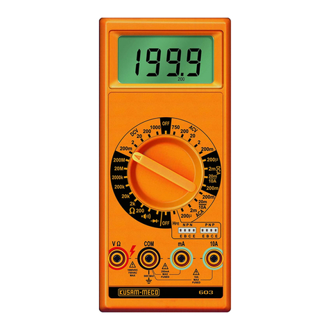
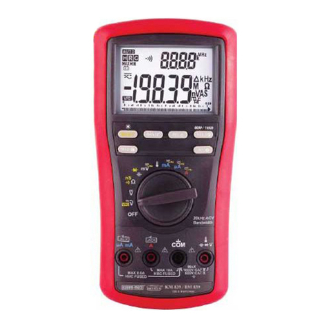
Kusam-meco KM 8045 User manual
Other Kusam-meco Multimeter manuals
Kusam-meco
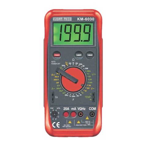
Kusam-meco KM 6030 User manual
Kusam-meco
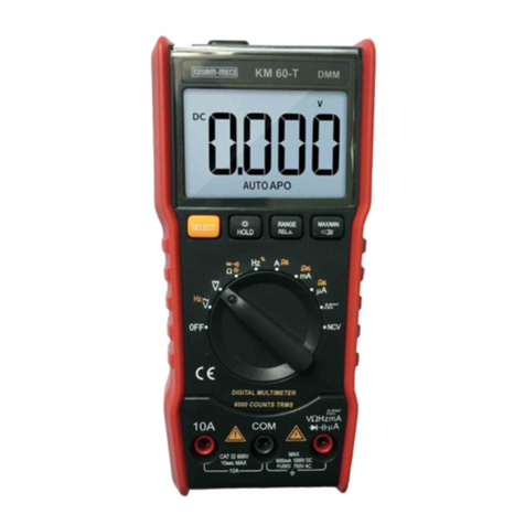
Kusam-meco KM 60-T User manual

Kusam-meco
Kusam-meco 801-L User manual

Kusam-meco
Kusam-meco KM 887 Installation manual
Kusam-meco
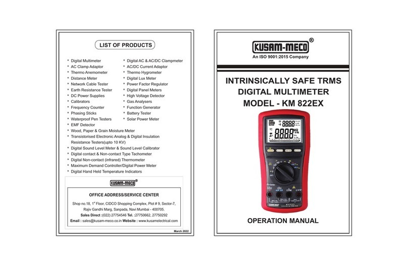
Kusam-meco KM 822EX User manual

Kusam-meco
Kusam-meco 405 User manual

Kusam-meco
Kusam-meco KM 6050 User manual
Kusam-meco
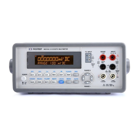
Kusam-meco M3511A User manual
Kusam-meco
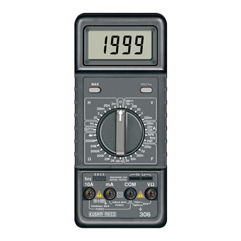
Kusam-meco 306 User manual
Kusam-meco
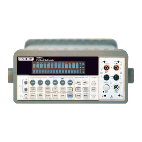
Kusam-meco M3500A User manual

Kusam-meco
Kusam-meco KM 2777 User manual
Kusam-meco
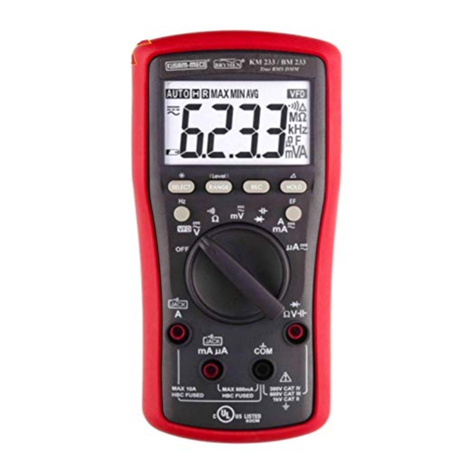
Kusam-meco KM 233 User manual

Kusam-meco
Kusam-meco KM 255 User manual

Kusam-meco
Kusam-meco KM 2778 User manual

Kusam-meco
Kusam-meco KM 656 User manual

Kusam-meco
Kusam-meco KM-DMM-41 Installation manual
Kusam-meco
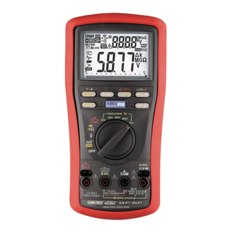
Kusam-meco KM 877 User manual
Kusam-meco
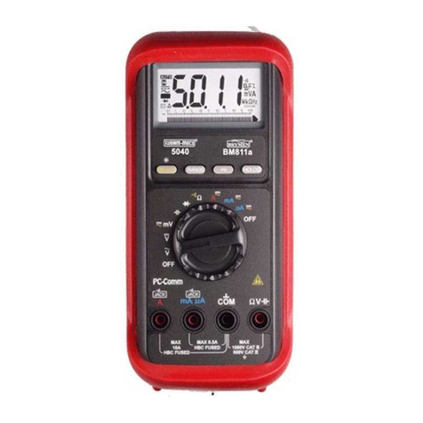
Kusam-meco 5040 User manual

Kusam-meco
Kusam-meco KM 525 User manual

Kusam-meco
Kusam-meco 8010 User manual
Popular Multimeter manuals by other brands

Gossen MetraWatt
Gossen MetraWatt METRAmax 6 operating instructions

PeakTech
PeakTech 4000 Procedure of calibration

YOKOGAWA
YOKOGAWA 90050B user manual

Gossen MetraWatt
Gossen MetraWatt METRALINE DMM16 operating instructions

Fluke
Fluke 8846A Programmer's manual

Tempo Communications
Tempo Communications MM200 instruction manual
