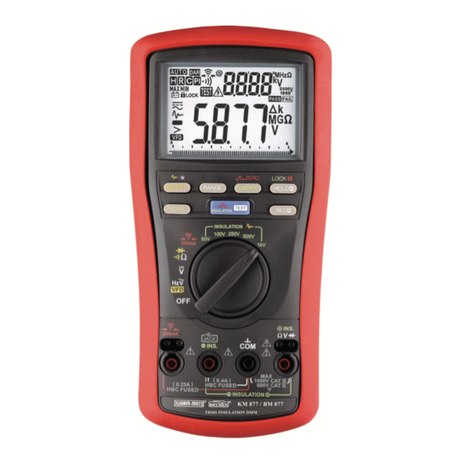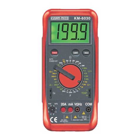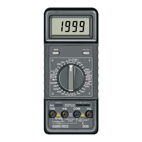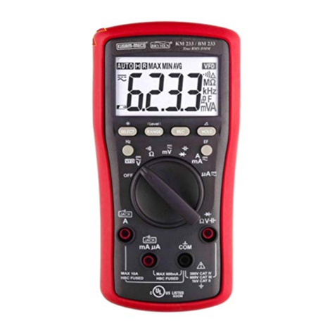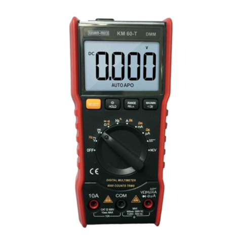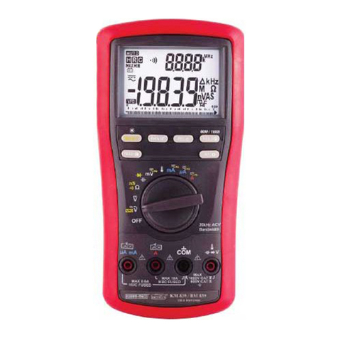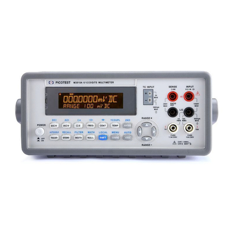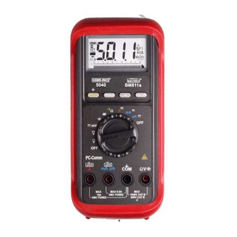
Nearly every electrical engineer has a hand held
Multimeter. We sometimes take them for granted, until
we damage them or “burn them out” if you incorrectly
connect your DMM to a circuit or have the DMM on
wrong setting, you damage the meter and possibly hurt
yourself. You can also get into trouble if you try to
measure the voltage across a charged capacitor.
DMM users frequently burn their meters by trying
to measure current the same way as they measure
voltage, Remember, you measure voltage across a
circuit, and current through a circuit. When you use the
current input, your DMM becomes a lower impedance
circuit element. If you accidentally connect this low
impedance path across your circuit, you’ll effectively
short-circuit it. You can, therefore send high current
through your meter and severely damage it. Unless the
meter has a fused input, you can even get an explosion
or fire.
Even if you correctly insert your DMM into the
circuit, you can still damage your meter. Don’t try to
measure current in excess of your meter’s capacity.
Handheld DMMs usually have a maximum current
rating of 10A or 20A.
If you are measuring current in industrial
environment, you can easily exceed those ratings. The
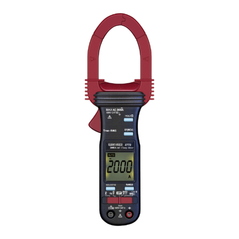
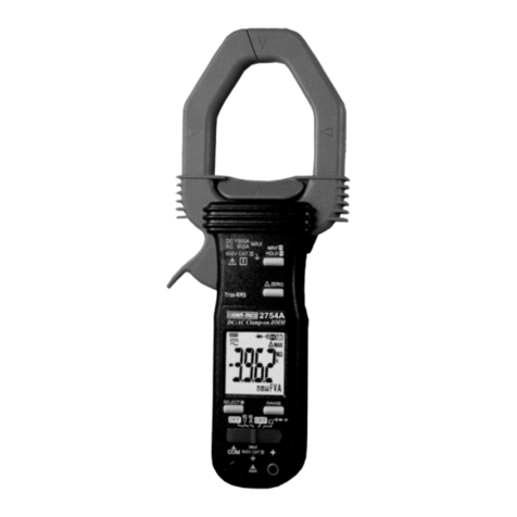
best way to avoid damage is to use a clamp meter or to
connect a clamp attachment to your DMM.
To prevent excess current from flowing through
your meter, always disconnect the test leads from the
circuit under test whenever you change DMM
functions, Set your meter to the correct function, say
current and its highest range for the setting, say 20A.
Next, connect the test leads before you apply power to
the circuit. To be safe, start by setting your meter to its
highest range first.
TAKE MEASUREMENT CAREFULLY AND YOU’LL
SPARE YOUR METER AND YOURSELF, SOME PAIN
Table of Contents
Title Page
Overview .......................................................1
Unpacking Inspection..................................1
Features........................................................2
General Specifications................................3
Electrical Specifications............................. 4
A. DC Voltage
B. AC Voltage
C. AC Current
D. DC Current
E. Resistance
F. Capacitance
G. Temperature
H. Frequency
I. Transistor hFE Test
J. Diode Test & Continuity
Rules For Safe Operation............................7
International Electrical Symbols................8
The Multimeter Structure............................ 9
Display Symbols.........................................10
Measurement Operation
A. DC Voltage ............................... 12
B. AC Voltage.................................13
C. AC Current.................................15
D. DC Current.................................16
E. Resistance.................................18
F. Capacitance...............................20
G. Temperature...............................21
H. Frequency..................................22
I. Diode Test & Continuity..............23
J. Transistor hFE Test....................25
Maintenance...............................................26
A. Replacing the Battery
Test Certificate........................................... 27
Warranty..................................................... 28


