INSTALLATION INSTRUCTIONS
1.LocateaconvenientplaceonthevehicletomounttheAUTOEJECT.Aminimumclearance
of 4” behind the mounting panel is required as well as 3 3/4” below the center line to clear the
ejection mechanism.
2. Place the template in position and center punch in 7 places.
3a. Drill 2 holes, 1/2” diameter. IMPORTANT THESE HOLES MUST BE DRILLED FIRST.
3b.Drill4mountingholes,3/16”diameterandone,21/4”clearanceholefortheAUTOEJECT.
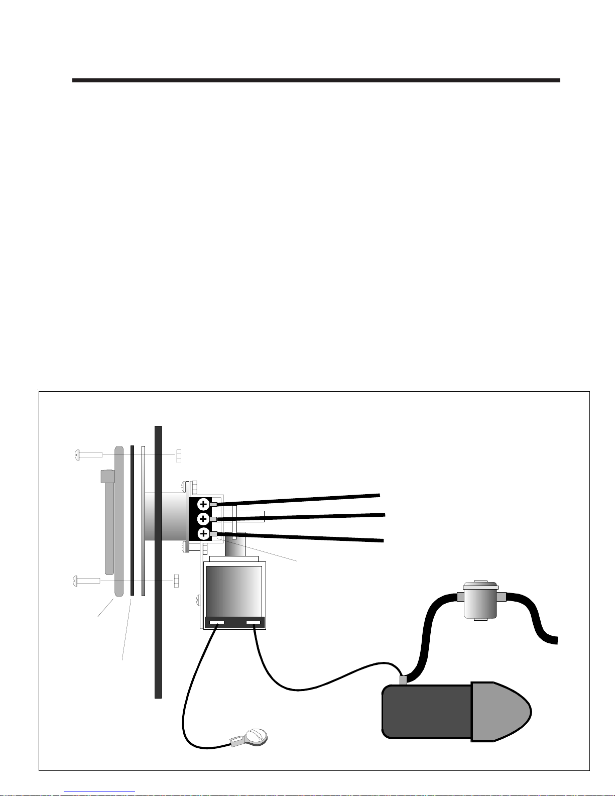
4.ConnectoneterminalofthesolenoidontheAUTOEJECTtothevehiclegroundandtheother
solenoid terminal to the vehicle’s starter. USE #16 GAUGE WIRE OR HEAVIER.
5. Crimp the ring lugs on the wire and connect the Green, Black, and White power wires to the
accessories on the vehicle.
6.Testinstallationbyinstalling matingconnectorintotheAUTOEJECT.Energizingthestarter
should energize the solenoid and eject the connector.
7.KeepconnectorandcontactsoftheAUTOEJECTclean.CleancontactswithWD-40solvent
as required. Lubricate contacts monthly with “vaseline” to insure free operation.
NOTE: USE ONLY CORD CONNECTOR SUPPLIED WITH THE AUTO EJECT
All connectors are not identical, using a substitue may result in unreliable
operation or failure of the AUTO EJECT to operate.
Note: TheAuto Eject is on the
outside of the truck wall. Note: use 12 gauge wire for 20 amps
and 14 gauge wire for 15 amps.
#8Hex Nut
#8 Screw
Green
Black
White
Ground
Line
Neutral
Ring lugs supplied
Weather
Proof Cover
Gasket
Truck Wall
Chassis
Ground
Solenoid
To Battery
VehicleStarter