manuals.online logo
Brands
  1. Home
  2. •
  3. Brands
  4. •
  5. Kutai electronics
  6. •
  7. Control Unit
  8. •
  9. Kutai electronics DSP-30 User manual

Kutai electronics DSP-30 User manual

KUTAI ELECTRONICS INDUSTRY CO., LTD.
TEL : +886-7-8121771 FAX : +886-7-8121775 Website : www.kutai.com.tw
Headquarters : No.3, Lane 201, Chien Fu St., Chyan Jenn Dist., Kaohsiung 80664, TAIWAN
L
23
L
12
L
31
VL
23
L
12
L
31
V
L
23
L
12
L
31
VL
23
L
12
L
31
V
L23 Fix Mode
L31 Fix Mode
L12 Fix Mode
Cyclic Mode
DSP-30
Percent Power Meter Display Module
Front Panel Display
DSP-30 Display panel has three four Digits bright LED’s that
shows (RMS) Voltage, Amps and percentage of full Power. The
user can easily read the real time 3 phase Voltage, Amps and
the percent of power that load is using now.
Programming Mode
There are three push buttons on the front panel for 100% full
power range setting. User need to set the full power range in
KVA before used. The buttons function description show as
below.
Program key:Press it will into program mode.
V
Up key:Press it will increase the setting value.
A
Down key:Press it will decrease the setting value.
How to Program the DSP-30 (1KVA / Unit)
Step-1:Press the program key for 2 seconds and then the
DSP-30 will into program mode and the screen show as
below.
Step-2:Use Up or Down key for 100% power range setting.
Step-3:Press program key again to exit the program mode.
Display Function
The operator can change the voltage and current display to be
fixed or cycling from phase to phase by simply using the button
next to each display.
To change the display mode, press the button next toit. See diagram.
Rear Panel Layout
Recommended Cut-Out 66 66 ± 0.5 mm
Voltage and Current Adjustment (If Necessary)
In the back of the DSP-30 module we have 4 push buttons for voltage
【V&V】andcurrent【A&A】adjustment.TheModulecomes
factory tested and calibrated and normally no changes are necessary.
But if any modifications are required,follow the procedures below.
Voltage Adjustment
(Please use and accurate RMS Voltmeter as your reference)
1.Start the generator. Set your reference AC voltage using your
Voltmeter.
2.Select the desire phase you need to re-calibrate using the front
display V】button on the display and hold.
3.Repeatedly press V) or V】
on back of module to adjust
the displayed voltage equivalent to your voltmeter.
4.Release the front V】button. The LED display will flash
continuously for 5 seconds.
5.After for 5 seconds then the system will automatically record
the new setting and return to normal.
6.If the display shows FAIL】the setting is invalid, and step 3
must be repeated.
Current Adjustment Procedure
(Please use Standard RMS Current meter for readings)
1.Set the dip switches to the correct CT in use.
2.Start the generator. And wait for the generator to stabilize.
3.Slowly add load to the genset until maximum rated load
current is reached for the CT in use.
4.Select desirephasecurrenttocalibrateusingthefront A button.
5.Repeatedly press A】
or Aon the back panelto adjusts
the displayed current to its equivalent on the current meter.
6.Release the front A button. The LED on the display will
flash continuously for 5 seconds.
7.After 5 seconds the system will automatically record the new
setting and return to normal.
8.If the panel display shows FAIL then the previous setting is
invalid, please return to step 5.
Setting The CT Value
Set the 5 pin dip switch for the CT (Current Transformer) and the
system phase you are using.
Dip Switch Setting Reference Diagram
Specification
ITEM
DESCRIPTION
DC Supply
9.0 ~ 36 V
Alternator Input Range
10 ~ 500VAC(Ph-Ph)
Alternator Input Frequency
50/60 Hz
CT Burden
Above 2.5VA
CT Secondary
5A
Max. CT Rated
3000A / 5A
Operating Temperature
-20 C to 70 C
Relative Humidity
90% or Below
Power Consumption
Under 2W
Weight
200 gram
Three Phase System Standard Wiring Diagram
Single Phase System Standard Wiring Diagram
Please link to http://www.kutai.com.tw for detailed manual
Battery
F4
+
1A
L1
J1-2
L3 L2
J1-6 J1-4
G
0.5A
F3
0.5A0.5A
F1F2
L1
L2
L3
L1
CT-L1
J2-15
DSP-30 Meter
J2-8 J2-9
V-V+
J2-12 J2-13 J2-14
K
LK
K L
CT-L2
L
CT-L3 L3
L2 LOAD
50/5A
100/5A
150/5A
200/5A
250/5A
300/5A
400/5A
500/5A
600/5A
800/5A
1000/5A
1200/5A
1500/5A
1600/5A
2000/5A
3000/5A
Programmer Table =ON =OFF
System Phase select 5
= 3 Phase
5
= 1 Phase
1 2 3 4 1 2 3 4 1 2 3 4 1 2 3 4
Current Transformer (CT)
J1-2J1-4
F4
1A
V+
J2-8 J2-9
V-
F2
0.5A 0.5A
F1
L2 L1
J2-12 J2-15
L1
K L
CT-L1 L1
L2
DSP-30 Meter
LOAD
GL2
Battery
+

Other Kutai electronics Control Unit manuals

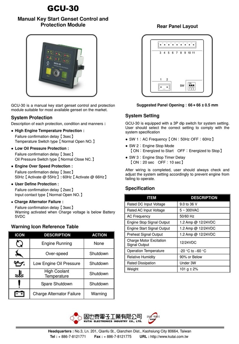
Kutai electronics GCU-20 User manual

Kutai electronics

Kutai electronics GCU-20 User manual

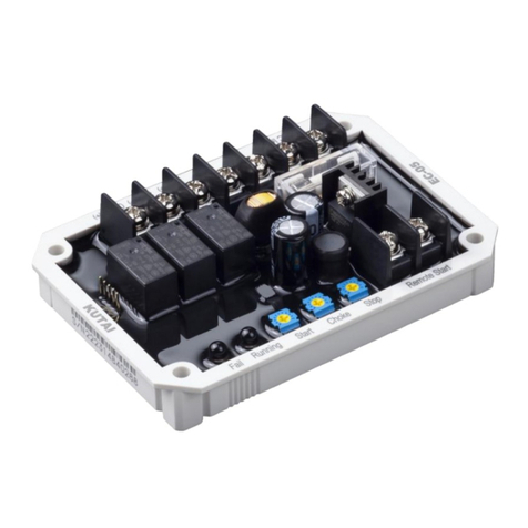
Kutai electronics EC-05 User manual

Kutai electronics

Kutai electronics EC-05 User manual

Kutai electronics GCU-30 User manual

Kutai electronics

Kutai electronics GCU-30 User manual

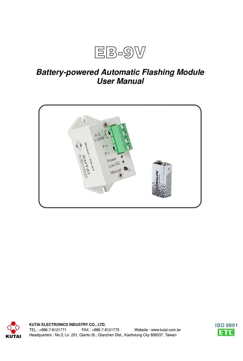
Kutai electronics EB-9V User manual

Kutai electronics

Kutai electronics EB-9V User manual

Kutai electronics EC-22 User manual

Kutai electronics

Kutai electronics EC-22 User manual

Kutai electronics GCU-100 User manual

Kutai electronics

Kutai electronics GCU-100 User manual

Kutai electronics ATS-33 User manual

Kutai electronics

Kutai electronics ATS-33 User manual

Kutai electronics ATS-PLC User manual

Kutai electronics

Kutai electronics ATS-PLC User manual

Kutai electronics ATS-380 User manual

Kutai electronics

Kutai electronics ATS-380 User manual

Kutai electronics ECU-04 User manual

Kutai electronics

Kutai electronics ECU-04 User manual

Kutai electronics GCU-3000 User manual

Kutai electronics

Kutai electronics GCU-3000 User manual

Popular Control Unit manuals by other brands

Ublox C027-U20 user guide

Ublox

Ublox C027-U20 user guide

Ublox MAX-M10M Integration manual

Ublox

Ublox MAX-M10M Integration manual

SimCom SIM7500 Series Command manual

SimCom

SimCom SIM7500 Series Command manual

Delta T13H Series instruction sheet

Delta

Delta T13H Series instruction sheet

red lion ITMA DC quick start guide

red lion

red lion ITMA DC quick start guide

BIG TREE TECH TMC2208 V3.0 user manual

BIG TREE TECH

BIG TREE TECH TMC2208 V3.0 user manual

Aqua Medic Refill System 2.0 Operation manual

Aqua Medic

Aqua Medic Refill System 2.0 Operation manual

Mini?Cam SoloPro+ CCU210 Original instruction manual

Mini?Cam

Mini?Cam SoloPro+ CCU210 Original instruction manual

Aero-motive 19105 installation instructions

Aero-motive

Aero-motive 19105 installation instructions

Carrier LonWorks i-Vu Link Integration guide

Carrier

Carrier LonWorks i-Vu Link Integration guide

GEM 762 Installation, operating and maintenance instructions

GEM

GEM 762 Installation, operating and maintenance instructions

DROPSA nano Progressive Replaceable USER OPERATION AND MAINTENANCE MANUAL

DROPSA

DROPSA nano Progressive Replaceable USER OPERATION AND MAINTENANCE MANUAL

Follett Ice Manager Operation and service manual

Follett

Follett Ice Manager Operation and service manual

EB TECHNOLOGY START S10 manual

EB TECHNOLOGY

EB TECHNOLOGY START S10 manual

Telegesis ETRX2-PA product manual

Telegesis

Telegesis ETRX2-PA product manual

AT&T 6386/33 Hardware installation

AT&T

AT&T 6386/33 Hardware installation

Ross SideBox Installation and setup

Ross

Ross SideBox Installation and setup

Honeywell PWT-BV Product data

Honeywell

Honeywell PWT-BV Product data

manuals.online logo
manuals.online logoBrands
  • About & Mission
  • Contact us
  • Privacy Policy
  • Terms and Conditions

Copyright 2025 Manuals.Online. All Rights Reserved.