manuals.online logo
Brands
  1. Home
  2. •
  3. Brands
  4. •
  5. Kutai electronics
  6. •
  7. Control Unit
  8. •
  9. Kutai electronics ECU-04 User manual

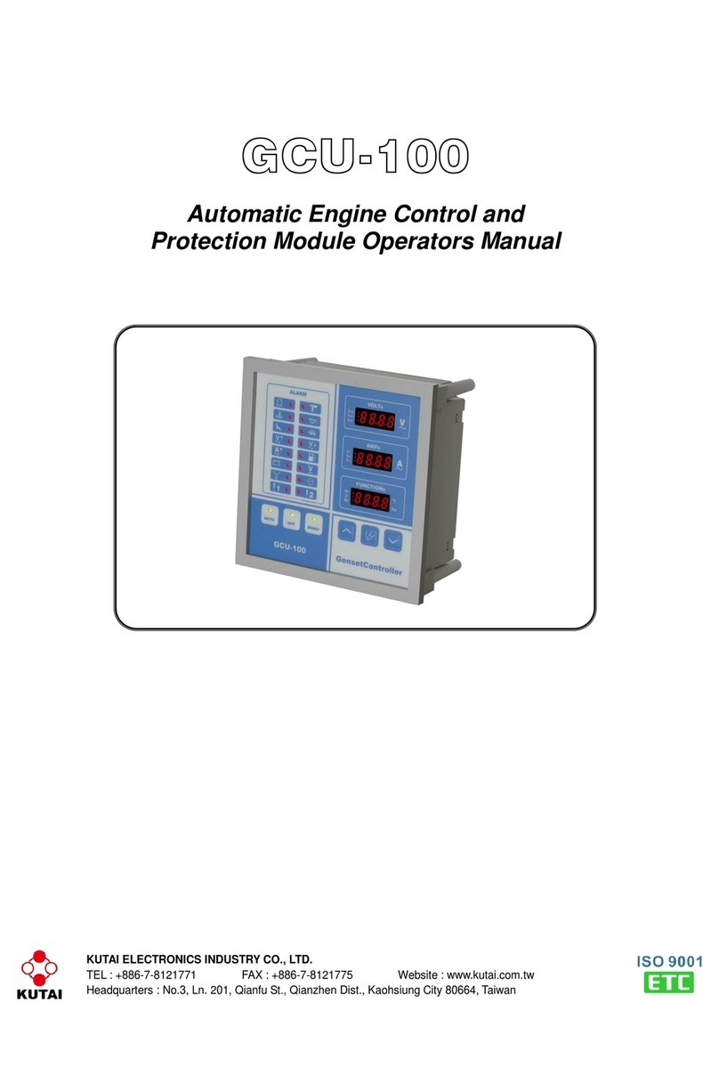
Kutai electronics ECU-04 User manual

KUTAI ELECTRONICS INDUSTRY CO., LTD.
TEL : +886-7-8121771 FAX : +886-7-8121775 Website : www.kutai.com.tw
Headquarters : No.3, Ln. 201, Qianfu St., Qianzhen Dist., Kaohsiung City 806037, Taiwan
ECU-04 Ver1.0
Control Unit for Key Switch
Type Generator
___________________________________________________________________________________________
2ECU-04
SECTION 1 : INTRODUCTION
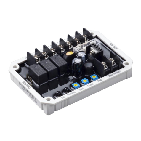
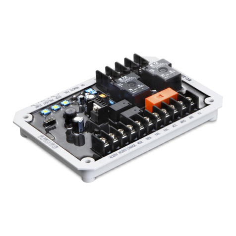
The ECU-04 Generator Auto Start Control, simply
changes any manual key start generator to auto-start
by automatically mimicking the action taken by
someone turning the panel key and starting the
generator manually.
The ECU-04 automatic initiation of the generators
starting cycle by using the standard two-wire signals
from any Automatic Transfer Switch or any standard
remote mounted ON / OFF switch.
In case of generator starting failures, this device has
maximum of 3 attempts of preheat and start with
adjustable time form1 to 25 seconds interval.
This module is composed of microprocessors to
minimized dimension. Encapsulated in factory
designed chassis to protect them from vibration and
moisture.
SECTION 2 : STANDARD FEATURES
●Small size, low cost, low power consumption and
easy to install.
●Connected by the terminal block. Easy for
installation and repairing.
●A single chip microprocessor is utilized.
●Epoxy encapsulation makes the ECU-04
dependable and reliability.
●Multi-start function. (The factory setting is 3 times.
The different Value from customer's request is
acceptable.)
NOTE
Don’t release the battery when engine is running.
Never feed charge motor voltage directly into
controller, to prevent damage to the controller
caused by high charge voltage.
SECTION 3 : SPECIFICATIONS
ITEM
DESCRIPTION
DC Supply
12 Vdc (ECU-05-12V) Max. Input 18 Vdc
24 Vdc (ECU-05-24V) Max. Input 36 Vdc
Alternator Input Voltage Range
100 240 Vac (+/- 10%)
Alternator Input Frequency Range
50 60 Hz
Static Power Consumption
Less than 0.03 watts
Starter switch Signal Output
30Amp @ 12/24 Vdc
Start Signal Output
30Amp @ 12/24 Vdc
Pre-heat or Engine choke Signal Output
30Amp @ 12/24 Vdc
Auxiliary Dry contact Output
20Amp @ 12/24 Vdc
Operating Temperature
-20 to +60 ˚C
Relative Humidity
Max. 95%
Dimensions
162.0 (L) x 112.0 (W) x 31.0 (H) mm
Weight
380 g +/- 2%
SECTION 4 : ELECTRICAL CONNECTIONS
PIN No.
DESCRIPTION
NOTES
1
DC Plant Supply Input (+v)
System DC positive input. (Battery Positive).
2
DC Plant Supply Input (-v)
System DC negative input. (Battery Negative).
3
Pre-heat or Engine choke Signal Output
Used to control the internal Heater Supply (+v).
30 Amp rated
4
Accessories “ON”Output
Connect to Key switch accessories ON position.
5
Start signal Output
Used to control the Starter Motor. Supply (+v).
30 Amp rated
6 & 7
Auxiliary Dry contact Output
OPEN when engine running
CLOSE when engine failure or stop
20 Amp rated
8 & 9
Remote start Signal input
Connect to A.T.S device or Remote Switch
10 & 11
Generator AC sensing input
Connect to alternator AC output.
___________________________________________________________________________________________
ECU-04 3
SECTION 5 : TIME DELAY SETTING AND
ALARM INDICATORS
●VR1:The engine pre-heat time adjustment knob
with 1 25 seconds range. 5 seconds are
recommended. ( Please refer to Figure 1 below )
●VR2:The start-up time adjustment knob with 1 25
seconds range. Please refer to the generator user's
guide. 4 8 seconds are recommended. ( Please
refer to Figure 1 below )
●L1:Remote start activated indicator LED. ( Please
refer to Figure 1 below )
●L2:Engine running normal indicator LED.
( Please refer to Figure 1 below )
●L3:Start fail indicator LED.
( Please refer to Figure 1 below )
●SW:ON for use on Diesel Engine with Pre-Heat
OFF for use on Gasline Engine with Carburetor
138.0
162.0
12
3
4
5
678910
11
SW
L3
L2L1VR2VR1
88.0
33.0
18.3
112.0
5.2
Unit : mm
Figure 1
___________________________________________________________________________________________
4ECU-04
SECTION 6 : CONNECTION DETAILS AND TYPICAL WIRING DIAGRAM
Battery (+)
Battery (-)
Strater "ON"
Accessories "ON"
Engine "Pre-Heat"
Ignition &
Accessories
Start
Pre-Heat
Stop
Heater
SW-ON
30A
30A
30A
20A
Remote
Start Switch
Open-STOP
Close-START
AC Input from Generator
From 100 to 240Vac
Aux. Dry Contact
Open-When Engine Running
Close-When Engine Stop
Starter
Generator
Key Switch
Remote
Start Switch
Open-STOP
Close-START
Battery (+)
Battery (-)
AC Input from Generator
From 100 to 240Vac
30A
30A
30A
20A
Start
Pre-Heat
Stop
Aux. Dry Contact
Open-When Engine Running
Close-When Engine Stop
Starter
Generator
Key Switch To Carburetor
SW-OFF
Strater "ON"
Accessories "ON"
Ignition &
Accessories

Other Kutai electronics Control Unit manuals

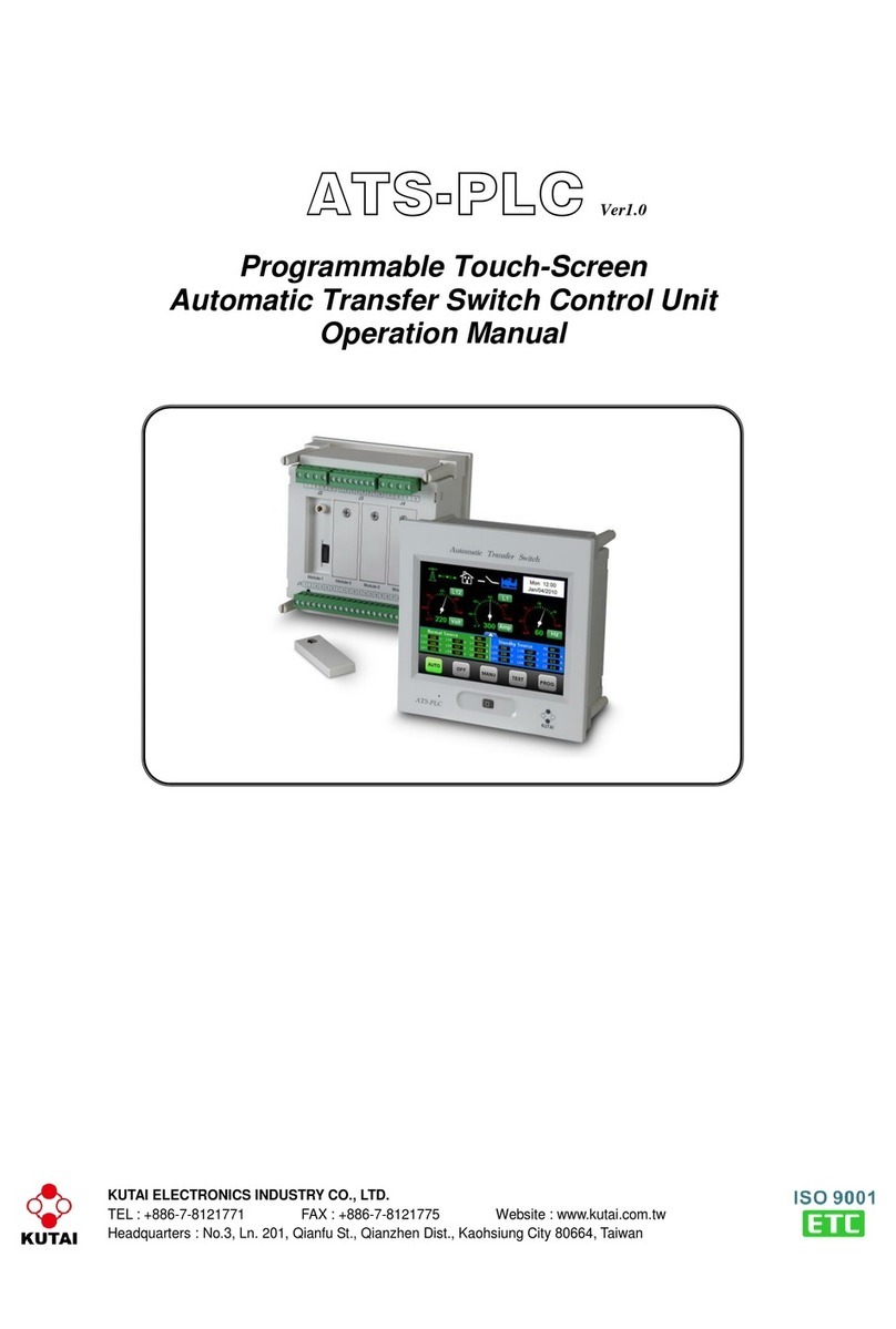
Kutai electronics ATS-PLC User manual

Kutai electronics

Kutai electronics ATS-PLC User manual

Kutai electronics EC-22 User manual

Kutai electronics

Kutai electronics EC-22 User manual

Kutai electronics EC-05 User manual

Kutai electronics

Kutai electronics EC-05 User manual

Kutai electronics GCU-100 User manual

Kutai electronics

Kutai electronics GCU-100 User manual

Kutai electronics ATS-33 User manual

Kutai electronics

Kutai electronics ATS-33 User manual

Kutai electronics ATS-380 User manual

Kutai electronics

Kutai electronics ATS-380 User manual

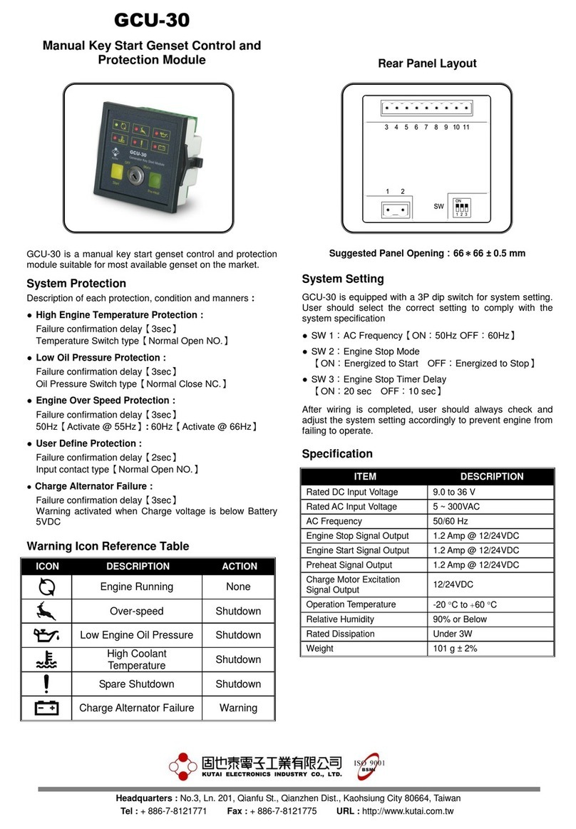
Kutai electronics GCU-30 User manual

Kutai electronics

Kutai electronics GCU-30 User manual

Kutai electronics GCU-3000 User manual

Kutai electronics

Kutai electronics GCU-3000 User manual

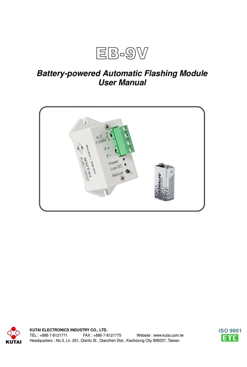
Kutai electronics EB-9V User manual

Kutai electronics

Kutai electronics EB-9V User manual

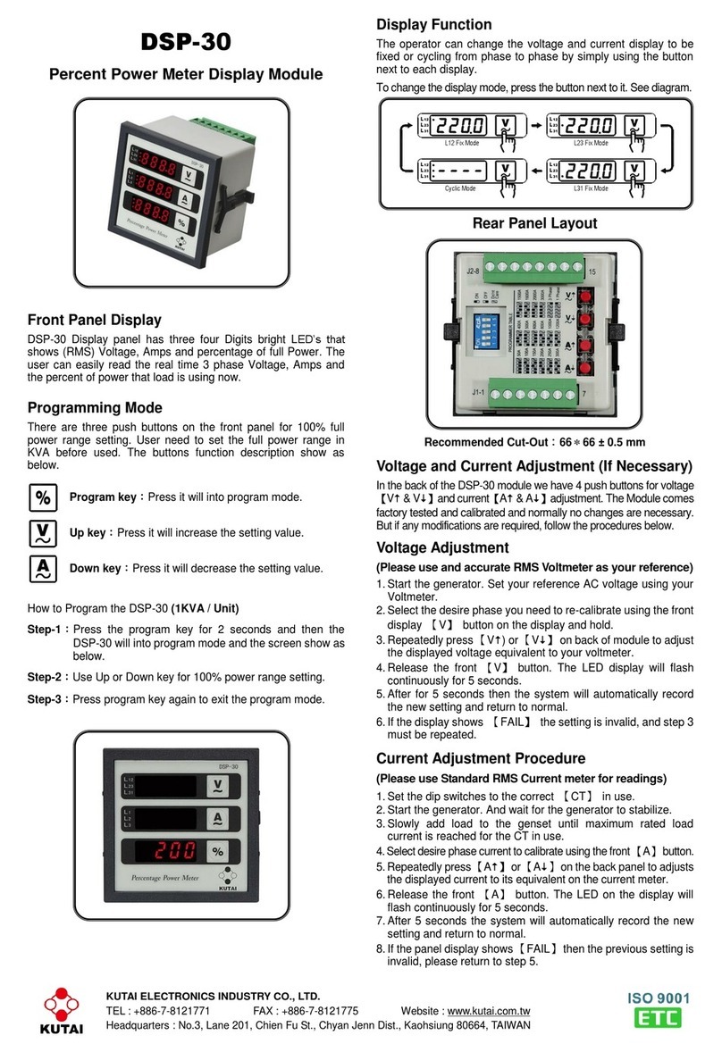
Kutai electronics DSP-30 User manual

Kutai electronics

Kutai electronics DSP-30 User manual

Kutai electronics GCU-20 User manual

Kutai electronics

Kutai electronics GCU-20 User manual

Popular Control Unit manuals by other brands

Siemens SIMATIC PRO Extension Units KP Series operating instructions

Siemens

Siemens SIMATIC PRO Extension Units KP Series operating instructions

Beijer Electronics OPT-2-EXTIO-BFI manual

Beijer Electronics

Beijer Electronics OPT-2-EXTIO-BFI manual

Linear Technology DC1811B-B manual

Linear Technology

Linear Technology DC1811B-B manual

Watts Ames 912GD Installation operation & maintenance

Watts

Watts Ames 912GD Installation operation & maintenance

Ensemble Designs Avenue 5030 user guide

Ensemble Designs

Ensemble Designs Avenue 5030 user guide

Steamist TSC-250T Installation and operating instructions

Steamist

Steamist TSC-250T Installation and operating instructions

Bailey Infi 90 IMFBS01 Instruction

Bailey

Bailey Infi 90 IMFBS01 Instruction

Carlisle MS Topcase 615300 Service manual

Carlisle

Carlisle MS Topcase 615300 Service manual

Asus AAEON NIM-S13A Quick installation guide

Asus

Asus AAEON NIM-S13A Quick installation guide

Trenz Electronic TE0712 200 2C10 Series Schematics

Trenz Electronic

Trenz Electronic TE0712 200 2C10 Series Schematics

Fanstel BlueFan BT680E manual

Fanstel

Fanstel BlueFan BT680E manual

Intelligent Appliance IA-2104-U user manual

Intelligent Appliance

Intelligent Appliance IA-2104-U user manual

Madas M16/RMO NA/NC manual

Madas

Madas M16/RMO NA/NC manual

Eaton Eaton 5PX Advanced user's guide

Eaton

Eaton Eaton 5PX Advanced user's guide

Campbell CompactFlash CFM100 instruction manual

Campbell

Campbell CompactFlash CFM100 instruction manual

Beninca Brain 24 MBE operating instructions

Beninca

Beninca Brain 24 MBE operating instructions

Waterbird ITSC1000 user manual

Waterbird

Waterbird ITSC1000 user manual

Malossi FORCE MASTER 2.1 Assembly instructions

Malossi

Malossi FORCE MASTER 2.1 Assembly instructions

manuals.online logo
manuals.online logoBrands
  • About & Mission
  • Contact us
  • Privacy Policy
  • Terms and Conditions

Copyright 2025 Manuals.Online. All Rights Reserved.