NOTE
!
CAUTION
C
!
14. Unplug SDD3 during lightning storms
or when unused for long periods of time.
15. Refer all servicing to qualified service
personnel. Servicing is required when the
SDD3 has been damaged in any way, such
as when the power-supply cord or plug
has been damaged; liquid has been spilled
or objects have fallen into the SDD3; rain
or moisture has entered the SDD3; the
SDD3 has been dropped; or when for
undetermined reasons the SDD3 does not
operate normally.
16. Do not remove top or bottom covers.
Removal of the cover will expose
hazardous voltages. There are no user
serviceable parts inside and removable
may void the warranty.
17. An experienced user shall always supervise
this professional audio equipment.
How to use this manual
As you read this manual, you’ll find figures
and diagrams to help you understand and
visualise what you’re reading. You’ll also find
numerous icons that serve as cues to flag
important information or warn you against
improper or potentially harmful activities.
Icons used include
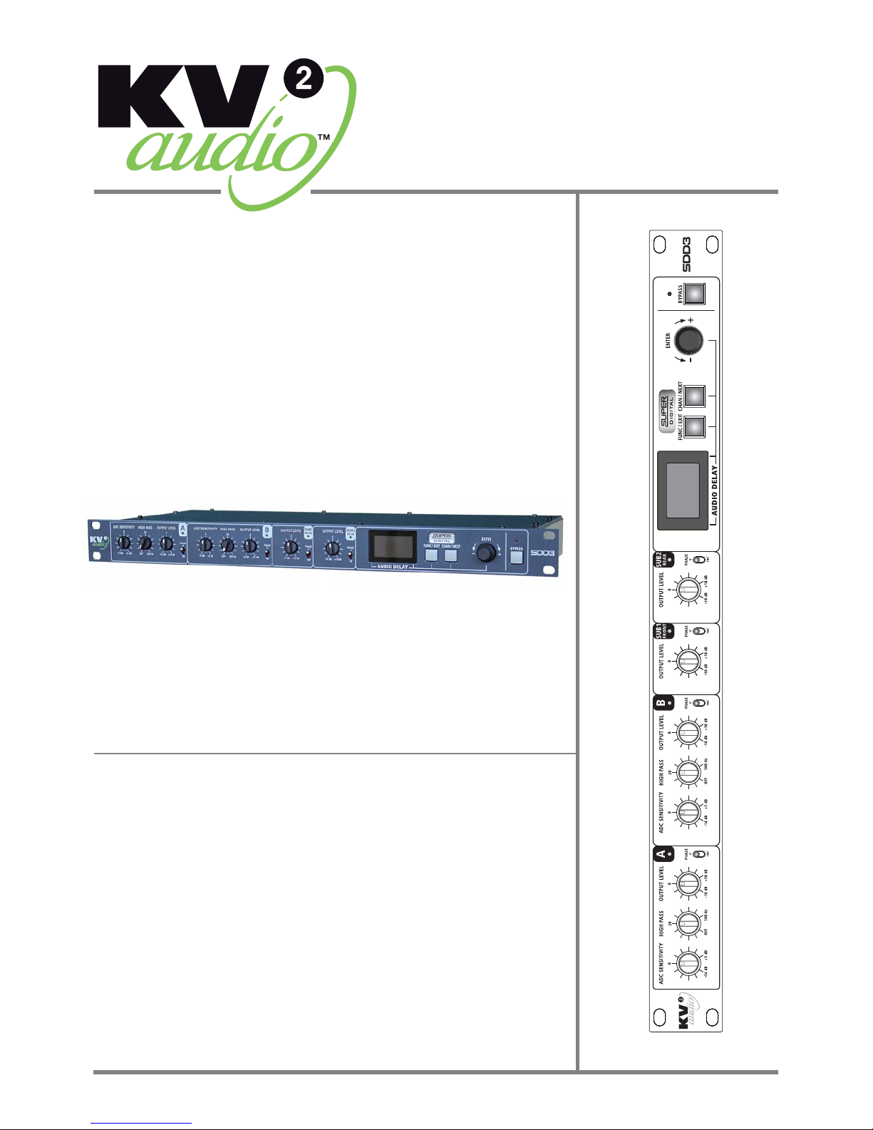
Introduction
“NOTE” identifies an
important or useful piece
of information relating to
the topic under discussion.
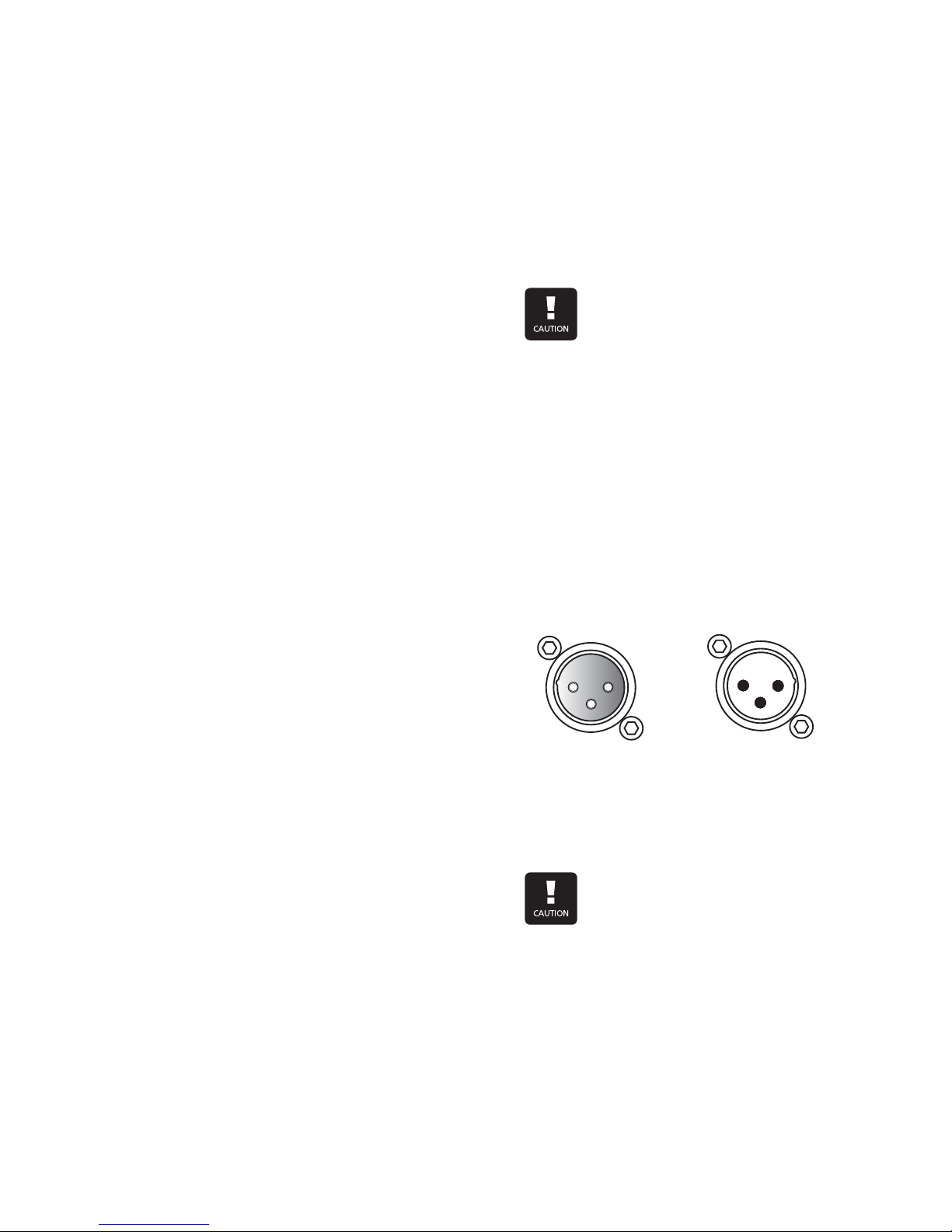
“CAUTION” gives notice
that an action can have
serious consequences and
could cause harm to
equipment or personnel,
delays, or other problems.
Important safety instructions
1 Read all product instructions.
2. Keep printed instructions, do not throw
away.
3. Respect and review all warnings.
4. Follow all instructions.
5. Do not use this unit near water, in
unprotected out door areas or in rain
or wet conditions.
6. Clean only with dry cloth.
7. Do not block any ventilation openings.
8. Install in accordance with KV2 Audio's
recommended installation instructions.
9. Do not install near any heat sources such
as heat radiators, heat registers, stoves
or other apparatus that produce heat.
10. Do not defeat the safety purpose of the
grounding type plug. A grounding type
plug has two blades and a third grounding
connector. The third connector is
provided for your safety.
If the provided plug does not fit into your
outlet, consult an electrician for
replacement of the obsolete outlet.
11. Protect the power cord from being walked
on or pinched, particularly at plugs,
convenience receptacles and the point
where they exit from the SDD3. The AC
mains plug or appliance coupler shall
remain readily accessible for operation.
12. Only use a ccessories specified by
KV2 Audio.
13. The unit is intended for use in a 19” rack.
Follow the mounting instructions.
CAUTION:
Installation should only be done
by experienced professionals.
!
CAUTION
Page | 4