5. DESCRIPTION
5.1. THE MASER CH1–76A APPLICATION
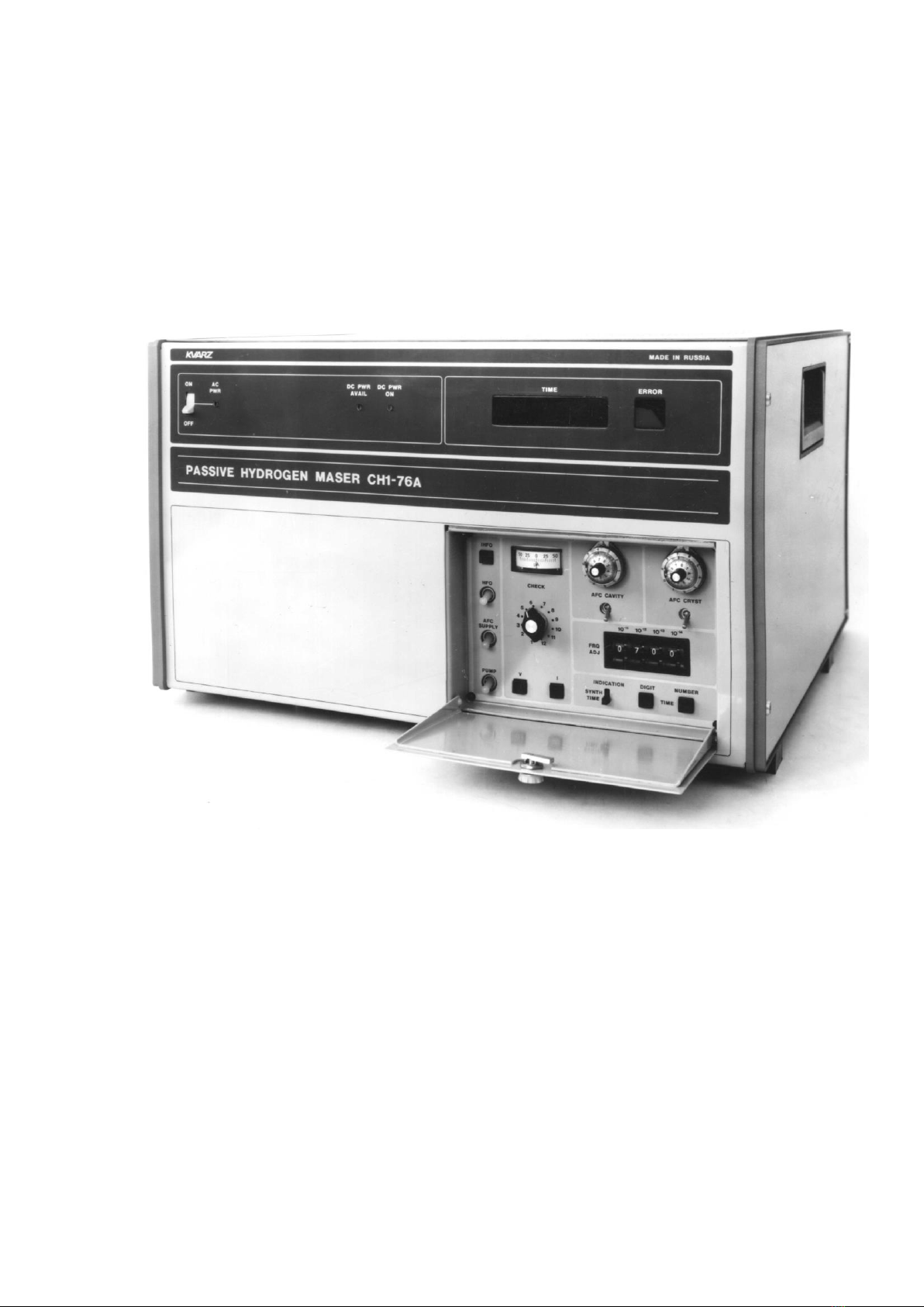
The Maser CH1–76A Passive Hydrogen Maser is used as a highly stable signal generator for time-
frequency measurements and for applications in reference measurement systems.
The Maser CH1–76A external view is shown in Fig. 1.
Typical applications are: national time and frequency calibration services and systems, navigation,
radiolocation, high precision physical measurements, metrology, frequency measurement
equipment, calibration of rubidium and cesium frequency standards, long baseline
radiointerferometers, telephone network timing, checkout equipment for GPS–GLONASS based
timing systems, etc.
The Maser CH1–76A is ruqqed, small size, relatively lightweight, transportable and highly stable
oscillator. It can be used in automated measuring systems by controlling the Maser's synthesizer
frequency and diagnostics state through the GPIB interface.
5.2. THE MASER CH1–76A PRINCIPLE OF OPERATION
The Maser CH1–76A is a Passive Hydrogen Maser.
Block diagrams (Fig. 5.1 and 5.2) describe the Maser's principal of operation.
It is based on the crystal oscillator frequency (fq) locking to the hydrogen discriminator atomic
emission line frequency. The influence of discriminator's RF cavity frequency (fc) fluctuations on
the emission line frequency is eliminated by the RF cavity frequency (fc) adjustment of the crystal
oscillator frequency (fq).
The automatic frequency control (AFC) unit through 5 MHz signal modulation with 12.5 kHz forms
a FM excitation signal. This signal is then multiplied by 20 and mixed with the frequency
synthesizer 20.4057 MHz signal. Finally, the 1420.405 MHz excitation signal is separated directly
in the
discriminator RF cavity from the 100 MHz signal 14th harmonic and synthesizer signal interaction.
In the atomic emission line and RF cavity discriminator interaction FM signal is converted into an
AM-FM signal. This signal envelope amplitude and phase data contain information about the
crystal oscillator frequency deviation from hydrogen atom emission line frequency and information
about the frequency fcdeviation from frequency fq. The discriminator output AM–FM signal again
passes to AFC unit, where it is amplified, converted and detected. After the amplitude detector 12.5
kHz signal is
applied to the selective amplifier, the output is connected to two-phase shifters. With the help of
these phases shifters RF cavity and crystal oscillator error signals are separated. From the phase
shifters the signals pass to two synchronous detectors. The 12.5 kHz reference signal is applied
simultaneously to the synchronous detectors. Then the synchronous detectors output signals are
applied to 2 integrating amplifiers, the output signals of which control the RF cavity and crystal
frequency.
The GPIB Interface enables the use of the Maser in automated measuring systems.
The Interface is designed to control the synthesizer frequency via an external computer and to
transfer the Maser's state diagnostic data.
Since the Maser CH1–76A internal systems have different warm–up times (Discriminator –
10 hours, other units –2 hours), they should be switched on separately as specified in the Operating
Manual.
In case of an AC power failure the Maser CH1–76A automatically switches to the external DC
power supply +(22–30) V, preserving its operating characteristics (assuming a DC supply is
connected).