KVT MF 1000 User manual

K U N S T S T O F F –V E R B I N D U N G S –T E C H N I K G M B H Stand: Okt-12
Werkering 6 –33609 Bielefeld –Tel. 0521 / 93207-0 –Fax 0521 / 93207-11 Kap. 7 –Seite 1
EWS system components
MF 1000 –MF 1500

K U N S T S T O F F –V E R B I N D U N G S –T E C H N I K G M B H Stand: Okt-12
Werkering 6 –33609 Bielefeld –Tel. 0521 / 93207-0 –Fax 0521 / 93207-11 Kap. 7 –Seite 2
7.1 Introduction
7.1.1 Purpose
Qualified staff must be able to correctly interpret and implement safety in-
structions and warnings. In addition, they must be familiar with the safety
concepts for automation technology and have obtained a corresponding
training. Use by unqualified staff or non-observance of the warnings in this
manual or the warning signs applied to the system components can result in
material damage or injuries to people.
Proper use means
Work on the EWS components is performed by specialists or appropri-
ately trained persons.
The EWS system components are in a technically fault-free condition.
The EWS system components are used in compliance with this product
manual.
It is recommended to thoroughly work through these instructions before using
the EWS system components.
7.1.2 General
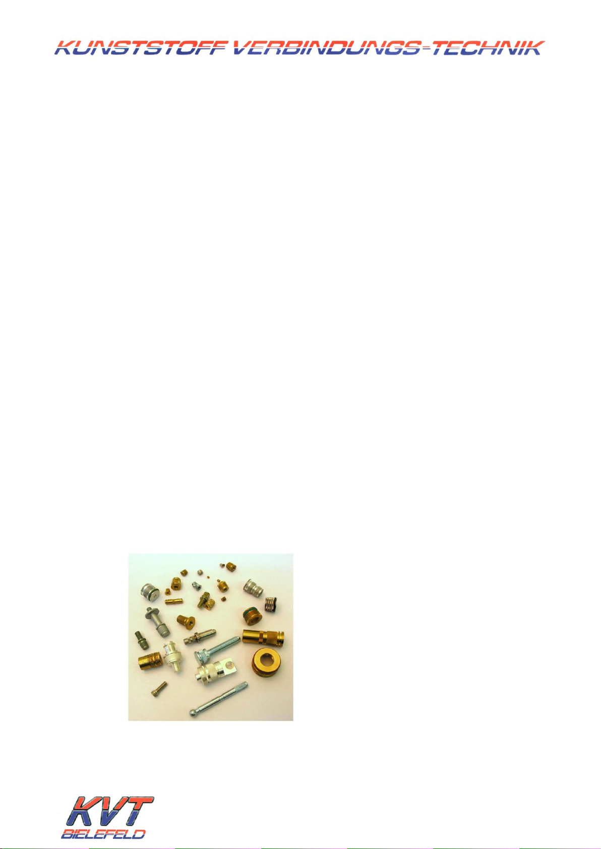
The requirement for a cutting edge joining technology has been achieved
by KVT Bielefeld with the development of EWS generators and electromag-
netic converters. It specifically concerns the installation of metallic compo-
nents and thread inserts in plastic parts.
High requirements with regard to strength and precision can be attained
with the EWS processes from KVT Bielefeld.
The EWS process is characterised by the following properties:
Contactless heating of the metal parts
Exact application of the necessary
energy requirement
Exact reproducibility of the assembly
temperature
Low thermal load on metal and plas-
tic
Shortest heating-up times
Shortest cooling-down times using
cold pressfit tool
Installation tolerances smaller than
0.05 mm
No material damage due to over-
heating
No hot machine parts
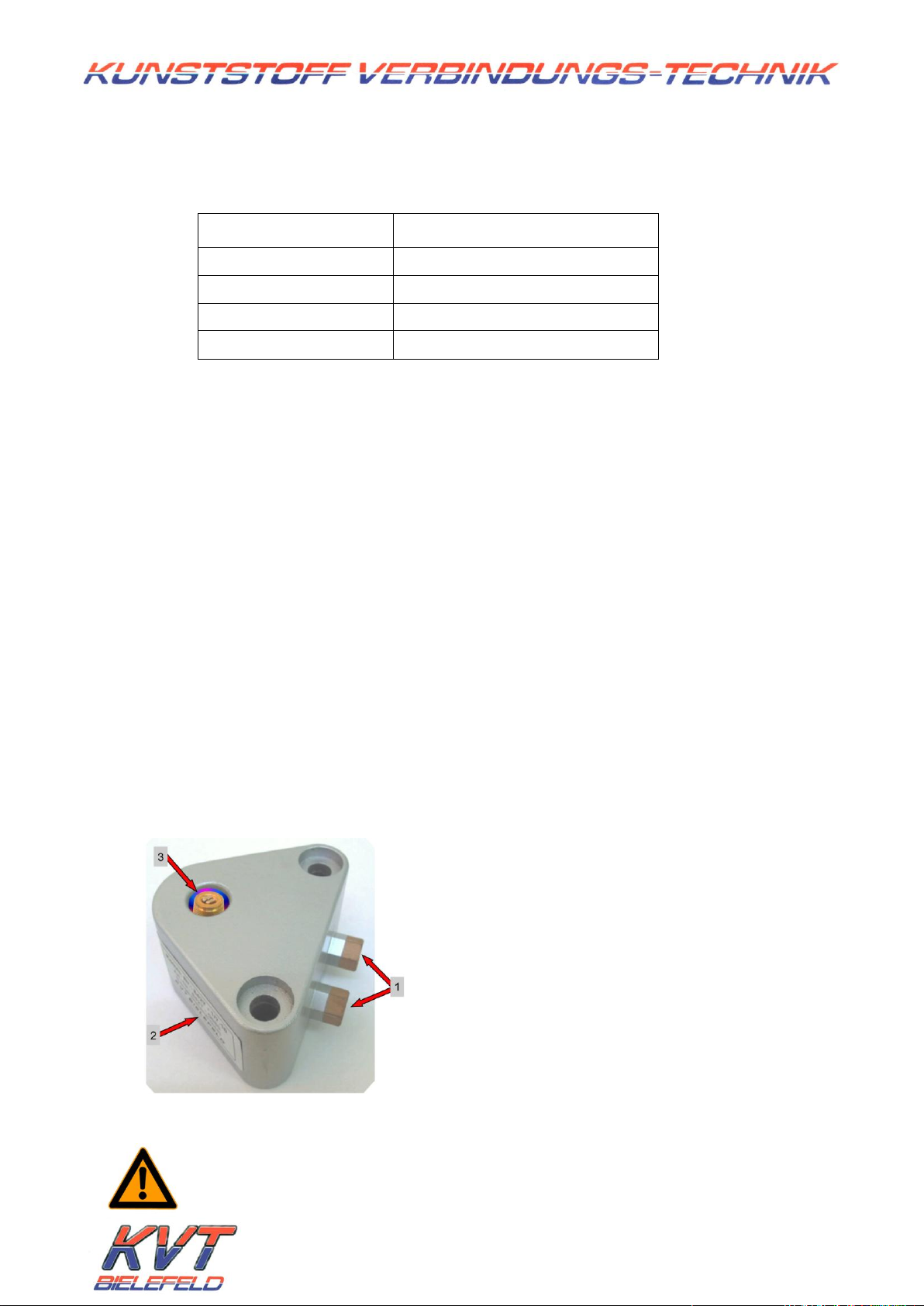
Photo 1: metallic assembly components

K U N S T S T O F F –V E R B I N D U N G S –T E C H N I K G M B H Stand: Okt-12
Werkering 6 –33609 Bielefeld –Tel. 0521 / 93207-0 –Fax 0521 / 93207-11 Kap. 7 –Seite 3
7.2 EWS generator MF 1000 –MF 1500
7.2.1 Mode of operation
The EWS generators were developed specially for EWS heating and operate
with frequencies of 15 to 80 kHz. The high performance was achieved by us-
ing thyristor technology and output adjustment optimised for the least losses.
Safety and monitoring functions are of course included in the electronic con-
trol and regulator unit.
The infinitely variable power setting makes it possible to optimally adjust the
output power for the particular application.
Photo 2: EWS generator MF 1000 –MF 1500
7.2.2 Controls and display elements
1Mains switch
2Fault display (fault indicator lamps)
3Display of the power output as a % of 1000 W or 1500 W
4Regulator for the output power
5Test button, activates the ERW generator
Photo 3: EWS generator, controls and display elements

K U N S T S T O F F –V E R B I N D U N G S –T E C H N I K G M B H Stand: Okt-12
Werkering 6 –33609 Bielefeld –Tel. 0521 / 93207-0 –Fax 0521 / 93207-11 Kap. 7 –Seite 4
7.2.3 Connections
116-pole socket board for the ERW connection cable
(see 7.6.6 EWS connection cable circuit diagram for the pin assign-
ments)
2Ready / fault message to an upstream control unit,
(5-pole, 270°) (see 7.6.7 fault circuit diagram for the pin assignments)
3Type plate with serial number
Photo 4: EWS generator, connections on the rear side
7.2.4 Fuse protection
1Mains cable
2Mains fuse, 10 A, for 1000 W and
12 A, for 1500 W
3Secondary fuse, 16A, flink
Photo 5: Fuse protection
7.2.5 Back-up fuse
Generator
Back-up fuse
Cable length
Cable cross-section
Socket
1 kW
1.5 kW
16 A
> 5m
1.5mm²
2.5mm²
Schuko 16A, 3-
pole
Table1: Back-up fuse

K U N S T S T O F F –V E R B I N D U N G S –T E C H N I K G M B H Stand: Okt-12
Werkering 6 –33609 Bielefeld –Tel. 0521 / 93207-0 –Fax 0521 / 93207-11 Kap. 7 –Seite 5
7.2.6 Overload control unit
All generators are fitted with an overload control unit. This equipment consists
of an optical display on the front side of the generator (fault display) and a
corresponding signal to the ready / fault message socket [changeover con-
tact].
Function: If the generator rated power, i.e. more than 100%, is exceeded, the
frequency search process function is triggered automatically. This means
that no continuous power output is guaranteed from this point onwards. The
fault LED starts to flash when this overload threshold is reached.
Simultaneously, the fault indicator relay is set. In this way, an electrical control
is possible as well as the optical control. The overload display is automatically
reset with the subsequent start impulse or by pressing the test button
(optional).
However, if the fault LED is lit with a steady light, this can be caused by
several things (defective secondary fuse, generator fault, incorrect
adjustment). For this, also see Table 7.7.1: faults and fault resolution and 7.7.2
fault diagnosis diagram. The generator fault can be reset by switching off
and then switching the ERW generator on again.
7.2.7 Dimensions and weights
EWS generator MF 1000 - 1500
Slot
19" slot, 4 HE, 360 mm deep
Weight*
18.5 kg
Depth*
420 mm (450 mm**)
Width*
500 mm
Height*
205 mm
Table 2: Dimensions and weights
(* with casing)
(**with EWS connection cable connected)

K U N S T S T O F F –V E R B I N D U N G S –T E C H N I K G M B H Stand: Okt-12
Werkering 6 –33609 Bielefeld –Tel. 0521 / 93207-0 –Fax 0521 / 93207-11 Kap. 7 –Seite 6
7.2.8 Technical data
EWS generator MF 1000 - 1500
Generator rated power
ca. 1200 W (MF 1000)
ca. 1700 W (MF 1500)
Mains connection
230V / 50Hz
max. output power
1000 W
1500 W
max. output current
up to 650 A
max. output voltage
50-300 V
Operating frequency
28 –35 kHz
Frequency control
automatic
Power adjustment
infinitely variable from 25% to
100%
Table 3: Technical data
7.3 EWS compensation MF1000
7.3.1 Mode of operation
The compensation (Photo 6) is interposed as connector for adjusting the EWS
converter(s) to the generator. Only one optimal adjustment (matching) of
the compensator to the EWS converter(s) used guarantees fault-free operat-
ing efficiency and maximum degree of efficiency of the EWS system.
Photo 6: EWS compensation MF 1000
Modifications to the matching must therefore only be made
by KVT Bielefeld or according to previous agreement!

K U N S T S T O F F –V E R B I N D U N G S –T E C H N I K G M B H Stand: Okt-12
Werkering 6 –33609 Bielefeld –Tel. 0521 / 93207-0 –Fax 0521 / 93207-11 Kap. 7 –Seite 7
7.3.2 Connections
The screw connections for the EWS converter(s) are on the front side of the
EWS compensation.
1Screw connection for the EWS converter(s)
(ferrule fitting Ø 10 mm)
Photo 7: Screw connection
The connection of the compensation to the converter is performed optional-
ly using special, flexible EWS tubed cable or with copper pipe.
The following connections and components are on the rear side of the com-
pensation.
Photo 8: Rear side of the compensation MF 1000
1. Start socket, the EWS generator can be activated using this by an up-
stream control unit with a voltage-free contact.
(see 7.6.7 Start circuit diagram for pin assignment)
2. 16-pole male connector for the EWS connection cable
3. LT 100 flow rate monitor
4. Quick-release connections for the coolant [inflow and outflow]
5. Fine filter
6. Type plate with serial number

K U N S T S T O F F –V E R B I N D U N G S –T E C H N I K G M B H Stand: Okt-12
Werkering 6 –33609 Bielefeld –Tel. 0521 / 93207-0 –Fax 0521 / 93207-11 Kap. 7 –Seite 8
7.3.3 Matching
The matching can be modified with the number and size of the installed
condenser blocks [1] = frequency adjustment, and with the transmission ratio
(tapping) [3] = impedance adjustment of the transmitter [2] inside the com-
pensator.
Photo 9: EWS compensation, inside and transmission ratio
Modifications must only be made after consultation with KVT Bielefeld
GmbH!
Condenser block
Transmitter
Transmission ratio
terminal block
Flow rate monitor evaluation board

K U N S T S T O F F –V E R B I N D U N G S –T E C H N I K G M B H Stand: Okt-12
Werkering 6 –33609 Bielefeld –Tel. 0521 / 93207-0 –Fax 0521 / 93207-11 Kap. 7 –Seite 9
7.3.4 Flow rate monitor and filter
The flow rate monitor guarantees that no start signal is sent to the EWS gen-
erator if there is insufficient flow rate in the cooling circuit. The EWS generator
start signal is interrupted as soon as the flow rate drops below the flow rate
value set on the evaluation board [4]. The generator is not ready for use.
The flow rate monitor evaluation board is inside the EWS compensation. No
modifications to the board must be made under any circumstances without
consulting KVT Bielefeld GmbH. If the generator starts although there is insuf-
ficient coolant flow, this results in irreparable damage to the connected EWS
converter.
Photo10: Flow monitor, filter casing
The mesh filter [1] absorbs dirt particles which can adversely affect the oper-
ating efficiency of the flow rate monitor.
The filter can be removed for cleaning or replacement by undoing the hex-
agonal nut.
Photo11: Filter
Coolant connections
LT 100 flow monitor
Filter casing
Mesh filter
Mesh size = 250 µm

K U N S T S T O F F –V E R B I N D U N G S –T E C H N I K G M B H Stand: Okt-12
Werkering 6 –33609 Bielefeld –Tel. 0521 / 93207-0 –Fax 0521 / 93207-11 Kap. 7 –Seite 10
7.3.5 Dimensions and weights
EWS compensation MF 1000
Weight
9.5 kg
Length
385 mm (410 mm*)
Width
375 mm
Height
160 mm
Table 4: Dimensions and weights
(* with quick-release coupling for coolant connection and plugged-in EWS
connection cable)
7.4 EWS converter
Using the EWS converters developed by KVT Bielefeld GmbH, metallic components
(insert heat element) such as thread inserts are heated without contact by elec-
tromagnetic energy.
A strong very local magnetic field is built up inside the EWS converter using a mid-
frequency high alternating current. Eddy currents are produced in the insert heat
element by this magnetic field. The insert heat element is heated in seconds by the
eddy currents.
The temperature that the insert heat element is heated to ban be adjusted for the
duration of the heating and the position of the insert in the converter during the
heating. This temperature can be reproduced very precisely. The optimal heating
parameters are determined by KVT Bielefeld GmbH using temperature measure-
ments.
The EWS converters must be integrated in the cooling circuit. The converter can on-
ly be protected from overheating and thus destruction by a sufficient coolant flow
rate.
1. Converter connections (internal thread G 1/8)
2. Converter identifier with serial number
3. Insert in heating position
Photo 12: ERW converter
Caution! A coolant flow rate that is too small can result in over
heating and thus destruction of the ERW converter.

K U N S T S T O F F –V E R B I N D U N G S –T E C H N I K G M B H Stand: Okt-12
Werkering 6 –33609 Bielefeld –Tel. 0521 / 93207-0 –Fax 0521 / 93207-11 Kap. 7 –Seite 11
7.4.1 Spare part supply
EWS converters are always special components matched to the respective
application. KVT Bielefeld does not kept any EWS converters in stock as spare
parts. Depending on production complexity, the replacement of an EWS
converter takes 8-10 working days!
It is the responsibility of the customer to provide one of the corresponding
spare parts necessary for production reliability.
Components made of high-quality technical ceramic are often used in ERW
converters. Depending on manufacture, these components are subject to a
replacement time of approx. 6 weeks!
Spare part supply by KVT Bielefeld it is basically not provided. The spare parts
necessary for production reliability must be provided by the customer.
The customer can estimate the delivery time and supply of spare parts
based on project-related spare part lists. The spare part lists are created on
request by KVT Bielefeld and provided to the customer.

K U N S T S T O F F –V E R B I N D U N G S –T E C H N I K G M B H Stand: Okt-12
Werkering 6 –33609 Bielefeld –Tel. 0521 / 93207-0 –Fax 0521 / 93207-11 Kap. 7 –Seite 12
7.5 EWS tubed cable
The ERW converters are connected to EWS compensation unit with the EWS tuned
cables developed by KVT Bielefeld. The tubed cables are flexible cables which
supply the coolant as well as the high alternating current to the EWS converter.
The converter can be moved independently of the compensator due to the flexibil-
ity of the EWS tubed cables.
The EWS tubed cables are produced in various lengths [between 400 mm and 1000
mm] by KVT Bielefeld. The length of the tubed cable is adapted for the respective
application. Gradation in 50 mm steps is usual.
Two EWS tubed cables = one pair of EWS tubed cables are needed for connecting
a converter to a compensator.
Photo 13: ERW pair of tubed cables
1. Connection to the compensator
2. Labelling, type / length
3. Spacing clips for parallel routing
4. Connection to the converter
Instead of tubed cables, the connection between the EWS compensation and the
EWS converter can also be made with soft copper pipe [diameter 8 or 10 mm].
However, the converter must then be firmly mounted.
KVT Bielefeld has the corresponding suitable screw connections for making these
connections in stock.
All metallic bare connections and screw connections must be con-
tact proof and electrically isolated.

K U N S T S T O F F –V E R B I N D U N G S –T E C H N I K G M B H Stand: Okt-12
Werkering 6 –33609 Bielefeld –Tel. 0521 / 93207-0 –Fax 0521 / 93207-11 Kap. 7 –Seite 13
7.6 Commissioning EWS components
Note: All technical equipment must be at room temperature before
commissioning.
7.6.1 Make connections
1. Connect generator and compensator with the supplied EWS connec-
tion cable.
1. Generator connection [sockets]
2. Compensator connection [pins]
3. Green flow rate control LED
Photo14: ERW connection cable
2. Screw the EWS compensation to the electromagnetic converter using a
pair of EWS tubed cables or copper pipe. All connections must be
made with an electrically conductive material (brass, copper).
Converter connection
Thread: G1/8
1. Copper sealing ring
Photo 15: EWS tubed cable –converter side -
Compensator connection
Ferrule fitting Ø 10 mm
1. Cutting ring
2. Union nut
Photo 16: EWS tubed cable –compensator side -
The standard EWS connection
cable is 1.5 m long. Special
lengths up to a maximum of 4 m
are available on request.

K U N S T S T O F F –V E R B I N D U N G S –T E C H N I K G M B H Stand: Okt-12
Werkering 6 –33609 Bielefeld –Tel. 0521 / 93207-0 –Fax 0521 / 93207-11 Kap. 7 –Seite 14
3. Make cooling circuit.
For this, connect the system cooler and compensator using the coolant
hoses.
Photo17: Coolant hose
1. Cooler connection –plug nipple DN 7.2
2. Compensator connection –Hasco coupling Z80/9/90
3. Coolant hose –length approx. 3 metres
4. Fill cooler according to instructions with coolant and bleed pump.
5. Connect generator and cooler with 230 V mains.
6. Switch on cooler
7. Switch on generator
(The fault control lamp lights immediately after switching on. It goes out
after a few seconds. Afterwards the equipment is ready for use.)
8. Set the power regulator to the smallest value.
9. Press the remote control switch or test button.
10. Adjust the power regulator as necessary to the required power for the
part to be heated.
11. The maximum coolant pressure must not exceed 4 bar. The tempera-
ture of the coolant should not be significantly less than room tempera-
ture (condensation forming).
12. Setting up work must only be carried out when the generator is
switched off.

K U N S T S T O F F –V E R B I N D U N G S –T E C H N I K G M B H Stand: Okt-12
Werkering 6 –33609 Bielefeld –Tel. 0521 / 93207-0 –Fax 0521 / 93207-11 Kap. 7 –Seite 15
Information:
It must be ensured, that the EWS hoses do not cross each other and that a
minimum spacing between them is maintained. When installed optimally,
they run parallel to each other. Improper installation can produce an upset
in the compensator balance. This has the result that the system does not op-
erate or even become active due to a fault of the generator. (see also Table
7.7.1)
Attention!
There is electricity in the EWS hoses during generator operation!
Therefore the transitions must be isolated after installing the ERW hoses.
When selecting the location for the compensator and the generator, it must
also be taken into account that these components are not designed for
permanent jerky movements. They must be parked on a vibration-free sup-
port. Furthermore, it must be ensured that the cooling slots are not obstruct-
ed. A suppression of the natural air circulation can cause overheating and
thus destruction of the electronic components.
7.6.2 Checking the water flow rate
The green LED on the EWS connection cable (on the compensation
side) is lit when the cooling circuit is running and the generator is
switched on (mains switch ON). The coolant flow can be stopped by
pinching one of the water bearing hoses (inflow or outflow) on the rear
side of the compensator. If the flow rate monitor is working correctly,
the green LED must go out now.
When the EWS generator is activated (external start or test button
pressed), the green LED does not light.
NOTE:
It is necessary to use distilled water and additive in the cooling circuit.
Recommended additive: 10% Coragard C330.

K U N S T S T O F F –V E R B I N D U N G S –T E C H N I K G M B H Stand: Okt-12
Werkering 6 –33609 Bielefeld –Tel. 0521 / 93207-0 –Fax 0521 / 93207-11 Kap. 7 –Seite 16
7.6.3 Maintenance instructions
The filter must be checked regularly and cleaned with compressed air.
If the mesh is clogged with deposits, it must be replaced.
For long shutdown periods, it must be ensured that there is no water in
the inflow and outflow of the compensation. This measure can be per-
formed with compressed air. This must also be carried out for the other
water-bearing EWS components.
7.6.4 Safety instructions
Electromagnetic radiation is produced during operation.
Heart pacemakers or other sensitive electronic compo-
nents can be damaged. Persons with heart pacemakers or
similar must keep away from these components during
operation, otherwise there is a danger to life.
The electricity supply must be disconnected for all mainte-
nance work, i.e. remove plugs or switch off the supply fuses.
Switching on again by unauthorised persons must be pre-
vented.

K U N S T S T O F F –V E R B I N D U N G S –T E C H N I K G M B H Stand: Okt-12
Werkering 6 –33609 Bielefeld –Tel. 0521 / 93207-0 –Fax 0521 / 93207-11 Kap. 7 –Seite 17
7.6.5 Function diagram EWS

K U N S T S T O F F –V E R B I N D U N G S –T E C H N I K G M B H Stand: Okt-12
Werkering 6 –33609 Bielefeld –Tel. 0521 / 93207-0 –Fax 0521 / 93207-11 Kap. 7 –Seite 18
7.6.6 EWS connection cable circuit diagram

K U N S T S T O F F –V E R B I N D U N G S –T E C H N I K G M B H Stand: Okt-12
Werkering 6 –33609 Bielefeld –Tel. 0521 / 93207-0 –Fax 0521 / 93207-11 Kap. 7 –Seite 19
7.6.7 Generator Start/Fault circuit diagram

K U N S T S T O F F –V E R B I N D U N G S –T E C H N I K G M B H Stand: Okt-12
Werkering 6 –33609 Bielefeld –Tel. 0521 / 93207-0 –Fax 0521 / 93207-11 Kap. 7 –Seite 20
7.7 EWS generator faults and fault resolution
7.7.1 Table
Mains
switch(1)
Mains
check(1)
Test but-
ton(5)
Fault dis-
play*(2)
Amplitude
display(3)
Fault
Fault resolution
ON
OFF
-
OFF
none
Mains fuse defec-
tive**
Replace mains fuse
ON
ON
-
ON
none
Secondary fuse de-
fective
Replace secondary
fuse
ON
ON
-
ON
none
Back-up fuse defec-
tive
Replace back-up fuse
ON
ON
-
ON
none
Generator fault
Replace generator
ON
ON
pressed
ON
none
Converter defective
wrong matching
Replace converter
new matching
ON
ON
pressed
OFF
none
None / too little
coolant flow rate
Switch on cooling cir-
cuit
Clean filter
Check smaller flow
amount
ON
ON
pressed
OFF
none
ERW cable not con-
nected
Connect ERW connec-
tion cable
ON
ON
pressed
OFF
pulsates
wrong matching
ERW hoses parallel
Reduce amplitude by
reducing power setting
(4) and restart genera-
tor
ON
ON
pressed
OFF
pulsates
Amplitude
regulator = 1
wrong matching
new matching
replace converter
ON
ON
pressed
pulsates
OFF
wrong matching
ERW hoses parallel
Reduce amplitude by
reducing power setting
(4) and restart genera-
tor
ON
ON
pressed
pulsates
OFF
wrong matching
new matching
replace converter
* Fault display: The fault display is deactivated by turning off and then turning the generator on
again
** Defective fuses can have various causes
This manual suits for next models
1
Table of contents