KW Aufzugstechnik GmbH Inbetriebnahme DAVID-613
DAVID-D613-Inbetriebnahme-V124-EE 18.02.2022 Seite - 10 -
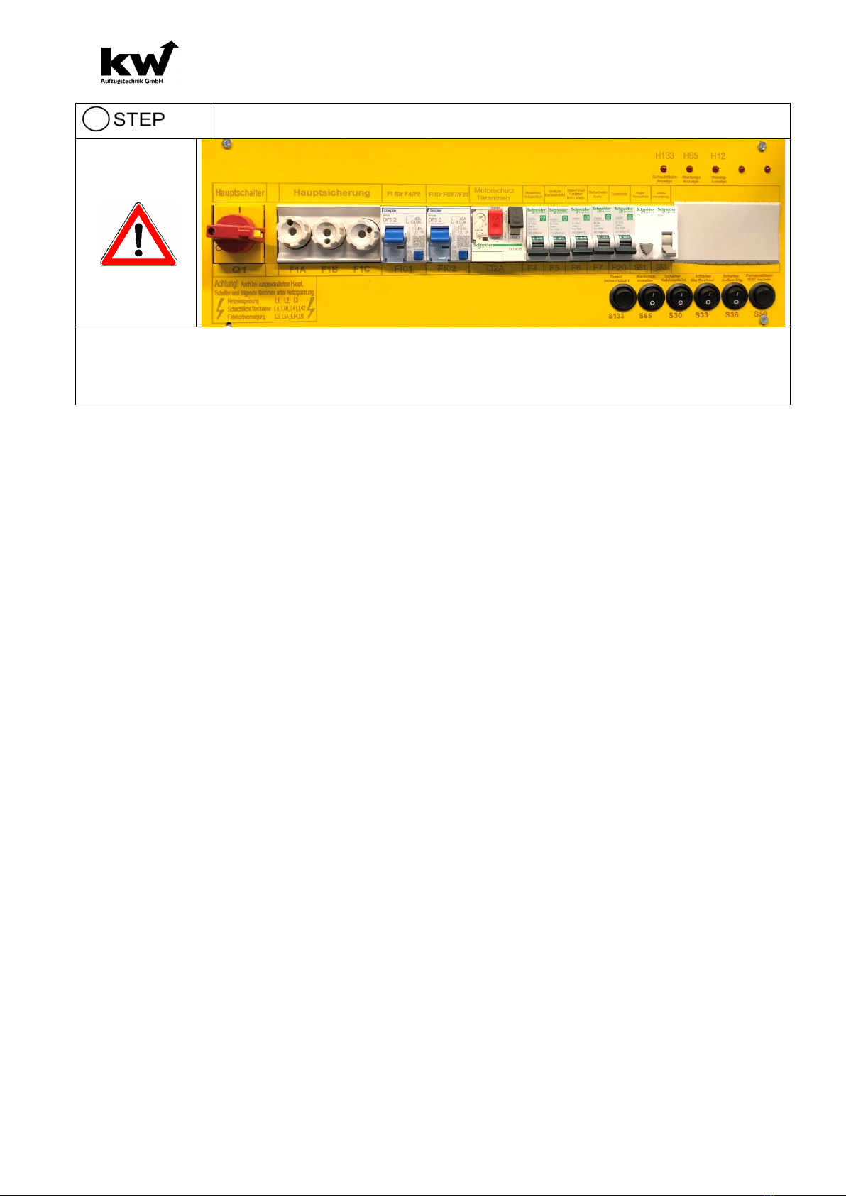
Preparing the Power Supply
Before connecting the main supply wire:
Switch main switch, all fuses, all switches off!
Attention! also with TÜV approval - insulation meas-
urement -> Switch off all switches and fuses!
Connection of the Power Supply-Wire
Attention! The mains supply may only be connected when the power is discon-
nected!
Connect all 5 wires of the main line (L1, L2, L3, N & PE)
After applying the main voltage, check all phases (L1 / L2 / L3) against "N"! The volt-
ages must always be 230V AC!
If a rotary field measuring device should be available, please carry out the measure-
ment. The rotating field should always be a right-hand rotation field!
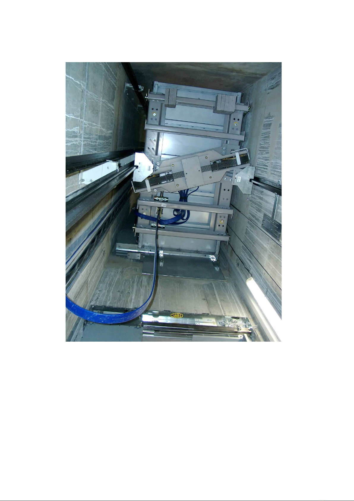
Connection of the Shaft-Pitch-Box
If there is a sub-distribution with separate protection of the lighting circuit,
the lighting circuit must be connected as follows:
The connection may only be made when the power is off! The terminals
for the connection can be found on the X1-XP circuit board.
(Wiring diagram sheet 1 of 8).
Connection of the Shaft-Top-Box X6
Danger! The SGS-92 pit box may only be connected when the power is
off!
The terminals for connection can be found on the circuit board X1, namely
X1 / 3, X1 / 4 and X1 / 5.
In addition, the pit bus cable (color gray / green) must be plugged into the
right RJ-45 connector on the BIS-80.
(Wiring diagram sheet 4 of 8 and Sheet 6 of 1).
Connection of the X7 pit brow box
The connection cable is to be led through the wall opening to the control cabinet.
Attention! The pit brow box may only be connected when the power is off!
The terminal for the connection can be found on the circuit board X1, namely X1 / 7
(Wiring diagram sheet 1 of 8)
Optional – Connection of the PTC thermistor
If the existing control device does not evaluate the PTC thermistor of the mo-
tor, the motor PTC thermistor can be connected to module X1.
Danger! The PTC thermistor contact may only be connected when de-ener-
gized! The terminal for connecting the PTC thermistor can be found on the
circuit board X1 /. (Circuit diagram sheet 1 of 8).
The terminals are 151 and 152