KW Variant 3 User guide

FÜR JEDEN ANSPRUCH DAS RICHTIGE FAHRWERK.
KW automotive GmbH
Aspachweg 14
74427 Fichtenberg
Telefon: +49 7971 9630 - 0
Telefax: +49 7971 9630 - 191
www.KWsuspensions.de
EINSTELLANLEITUNG
SETUP MANUAL

Einstellanleitung / Setup Manual
30.10.2020 Seite / Page 1
Einstellanleitung KW Variante 3
Nr. 685 77 027
Unser 2-fach verstellbarer Dämpfer basiert auf dem Prinzip des 2-Rohrdämpfers. Je nach Bestückung, in
Abhängigkeit von Abdichtung und Verstellmechanismus, mit einer Gasfüllung von 3 bis 8 bar oder als
drucklose Ausführung.
Die Druckstufe wird über unser patentiertes 2 Wege Bodenventil geregelt, die Zugstufe über das an der
Kolbenstange angebrachte Zugstufenventil.
Die Dämpfer sind getrennt und voneinander unabhängig in Druck- und Zugstufe einstellbar.
Zugstufe:
Die Zugstufeneinstellung erfolgt am oberen Ende der Kolbenstange und kann mit dem mitgelieferten
Inbusschlüssel vorgenommen werden. Die Einstellung wird hier vom geschlossenen Zustand (max. hart)
ausgehend vorgenommen. Die maximale Härte wird durch drehen nach rechts (im Uhrzeigersinn) erreicht.
Der wirksame Einstellbereich beträgt 0 - 16 Klicks auf.
Geringe Zugstufenkräfte verbessern den Fahrkomfort bei langsamer Fahrt, vermindern jedoch
insbesondere bei entsprechender Einstellung die Stabilität und Lenkpräzision bei schneller Fahrt.
Hohe Zugstufenkräfte verbessern an der Vorderachse nochmals das Handling, unter Umständen aber auf
Kosten der Haftung. Der Fahrkomfort wird stark eingeschränkt.
Keinesfalls darf eine Achse ganz hart, in Kombination mit der anderen ganz weich gefahren werden!
Achtung: Die Verstellspindel betätigt ein feinmechanisches Ventil. Bitte versuchen Sie keinesfalls
mit Gewalt das Ende des Verstellbereichs zu überschreiten. Dies beschädigt die Einstelltechnik.
+ hart
- weich
+ hart
- weich
- weich + hart

Einstellanleitung / Setup Manual
30.10.2020 Seite / Page 2
Druckstufe:
Die Einstellung der Druckstufe erfolgt am Boden des Dämpfers über einen Verstellstift mit 4 Löchern oder
einem Innensechskant. In diese Löcher kann je nach Fahrzeug und Zugänglichkeit mit einem Drahtstift
oder mit einem kleinen Inbusschlüssel eingegriffen werden. Die Verstellung erfolgt üblicherweise in 3
Klicks, feinere Einstellungen sind selbstverständlich möglich.
Die Einstellung wird ausgehend vom geschlossenen Zustand des Ventils (max. hart) vorgenommen. Der
geschlossene Ventilzustand wird in Drehrichtung rechts (im Uhrzeigersinn) erreicht. Der max. wirksame
Einstellbereich beträgt 0 – 12 Klicks auf.
Nach mehrmaliger Verstellung ist es sinnvoll beide Dämpfer einer Achse ausgehend vom geschlossenen
Zustand abzugleichen.
Die Druckstufen nimmt maßgeblich Einfluss auf Handling und Fahrverhalten.
Achtung: Die Verstellspindel betätigt ein feinmechanisches Ventil. Bitte versuchen Sie keinesfalls
mit Gewalt das Ende des Verstellbereichs zu überschreiten. Dies beschädigt die Einstelltechnik.
Nachfolgend empfehlen wir folgende Grundeinstellung als Ausgangsbasis:
VA Zug: 9 Klicks offen Druck: 5 Klicks offen
HA Zug: 12 Klicks offen Druck: 6 Klicks offen
- weich
+ hart - weich
+ hart
- weich
+ hart

Einstellanleitung / Setup Manual
30.10.2020 Seite / Page 3
Set Up Manual KW-Variant 3
No. 685 77 027
Our 2-way adjustable competition shock absorber is based on the KW twin tube damping system, and
features independent rebound adjustment. Depending on the sealing and the adjusting system of the
individual kit, our systems may be charged with pressures of 3 to 8 bars, or without any pressure at all.
Adjusting rebound:
The rebound adjustment is positioned in most cases at the end of the piston rod (top of strut). Please use
the supplied KW adjustment wheel on the extruded tab adjuster for all adjustments.
1st step: Place the KW adjuster on the adjustment Allen bolt.
2nd step: Turn the adjuster counter to the right (clockwise) until it stops. The damper is now adjusted to
full hard (clockwise = harder).
3rd step: Turn the KW adjuster counter-clockwise to soften the rebound setting to the desired level. The
effective adjustment range is from 0 - 16 clicks / 0 - 2,75 turns open.
Attention:
Never drive the vehicle with the shock absorbers set to full hard or full soft! Never apply force to the
adjusting mechanism of the shock absorber. As soon as you reach the end of the adjustment range, you
will recognize a certain resistance. Stop turning to avoid damage to the bottom valve.
Rebound adjusting principles:
In general a soft rebound adjustment provides a comfortable ride at low vehicle speeds but the vehicle will
have less stability at higher speeds, especially on the front axle (vehicle will tend to float at higher speeds).
A hard rebound adjustment offers more stability but could reduce vehicle grip (i.e. the vehicle will tend to
skip across road imperfections, reducing traction).
+ hard - soft
+ hard
- soft
+ hard
- soft

Einstellanleitung / Setup Manual
30.10.2020 Seite / Page 4
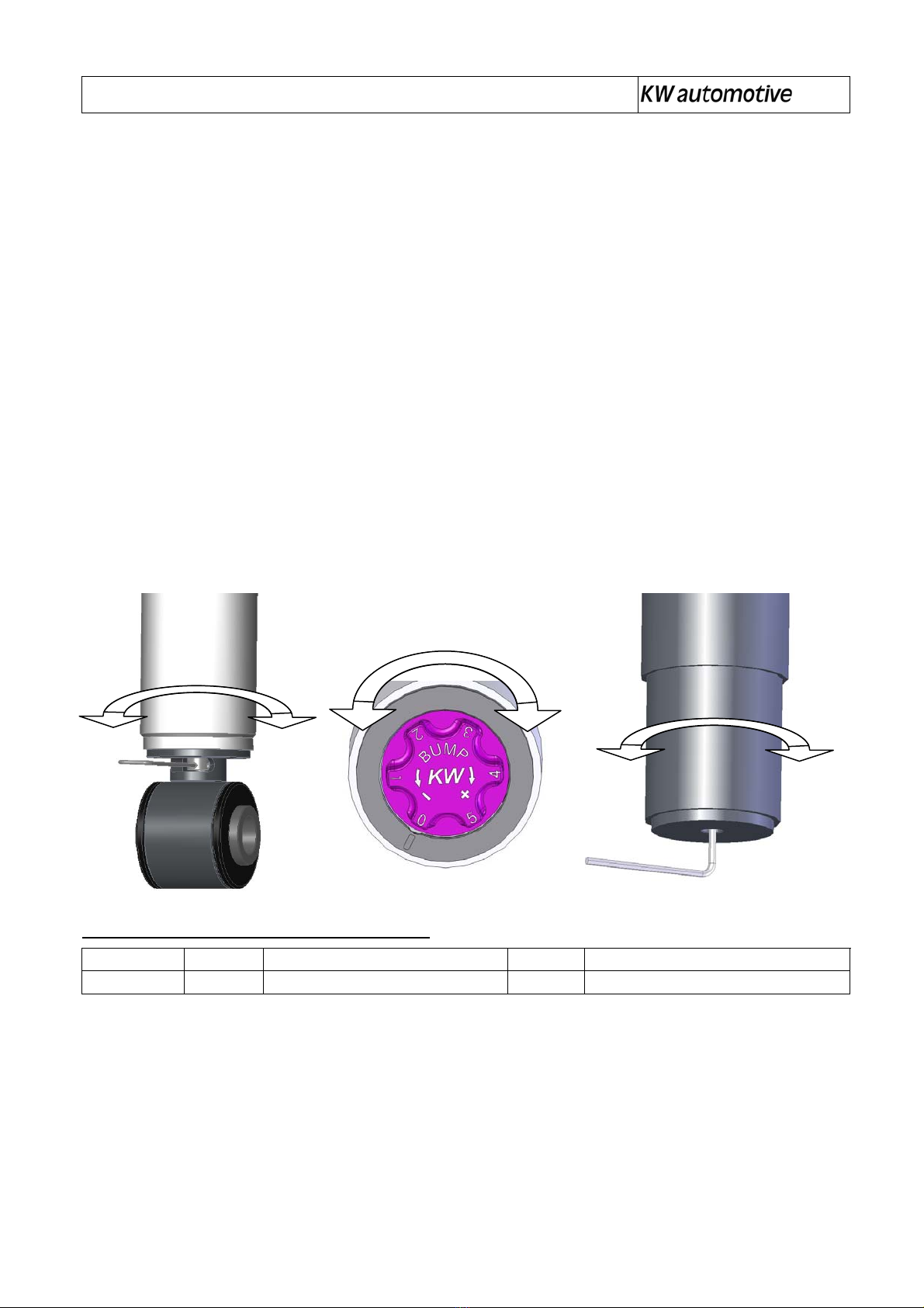
Adjusting the bump/compression:
The compression forces can be adjusted on our patented 2-way bottom valve. Access to the bump valve
in most instances is found on the bottom of each shock case. Hardness adjustment on the rebound valve
is made on the end of the piston rod with the supplied setting wheel or with a 2mm Allen key.
Adjusting bump:
Bump forces, especially on low damper speeds, have a great influence on handling and driving behaviour
of your car. The setting of the bump forces will be made from the bottom of the shock case. Behind the
adjusting grove you gain access to a pin with 4 holes. With the supplied small key, the adjusting pin can be
adjusted by 3 clicks in either direction. Smaller increments are possible.
Before performing any adjustments, the valve must be closed by turning the adjuster clockwise until it
stops. In this position, the shock will be at full hard, or “maximum power”. From here, the adjustment range
is 12 clicks.
To avoid the mismatch of the dampers when actively changing settings, you should close the valve from
time to time to re-calibrate the settings from side to side.
Bump adjusting principles:
Generally, hard low speed bump settings will stabilize the corresponding axle (less over steer on the rear,
for example) or offer the front a more precise steering response. Too much low speed bump power will
decrease grip!
Depending on the valve configuration found inside the kit, maximum bump forces will not influence the
suspensions response when encountering hard bumps, such as curbs on the racetrack.
Attention! Do not turn the adjusting spindle by force when you reach the end of the adjustment
range, this may damage the fine valve inside the system!
Our recommendation for your car to start with:
Front axle Rebound: 9 Clicks open Bump: 5 Clicks open
Rear axle Rebound: 12 Clicks open Bump: 6 Clicks open
+ hard
- soft
+ hard - soft
+ hard
- soft
This manual suits for next models
1
Table of contents
Languages:
Other KW Industrial Equipment manuals