KWE Versatronik COMO OT User manual

CONTROL
Versatronik®COMO OT
OpenTherm
Room Temperature Controller
This is not a safety control.
Cautionary Statement
Please observe the safety instructions and
read through this manual carefully before
commissioning the equipment.
IMPORTANT
Read and save these instructions for
future reference
1
2:47
Installation and Operating Manual

2
KWE P/N 542 019 Versatronik COMO OT V1.1 06/2009 Technical information subject to change without notice
Table of Contents
Caution, Warning Trademark Information Section 1
Control Mounting and Installation Section 2
Boiler Control Wiring Overview Section 3
Mounting Wall Base and Room Controller
Wiring Room Controller
Outdoor temperature Sensor Connections
Remote Telephone Switch Wiring
Mode Selector Switch
Menu Structure Overview
Changing the Settings
Expert Values
Errors
Start-up and Commissioning
Technical Data

3
KWE P/N 542 019 Versatronik COMO OT V1.1 06/2009 Technical information subject to change without notice
About these instructions
→ Warnings draw your attention to
the presence of potential
hazards or important product
information.
Take note of all symbols and notations intended to draw attention to potential hazards or
important product information. These include “WARNING”, “CAUTION” and “IMPORTANT”.
See below.
!
WARNING
!
Indicates an imminently hazardous
situation which, if not avoided,
could result in death, serious injury
or substantial product/property
damage.
CAUTION
!
Indicates an imminently hazardous
situation which, if not avoided,
may result in minor injury or
product/property damage.
IMPORTANT
→ Cautions draw your attention to
the presence of potential
hazards or important product
information.
→ Helpful hints for installation,
operation or maintenance which
pertains to the product.
CAUTION
Static sensitive components may
be damaged by improper handling
or work within the control. Ensure
all possible measures are taken to
eliminate build-up of static
electricity.
Caution, Warning and Trademark Information

4
KWE P/N 542 019 Versatronik COMO OT V1.1 06/2009 Technical information subject to change without notice
Important Regulatory and Installation Requirements
Codes
The installation of this unit must
be in accordance with local
codes.
All electrical wiring is to be done
in accordance with the latest
edition of CSA C22,1 Part 1 and/
or local codes. In the U.S. use
the National Electrical Code
ANSI/NFPA 70.
The installing contractor must
comply with the Standard of
Controls and Safety Devices for
Automatically fired Boilers, ANSI/
ASME CSD-1 where required by
the authority having jurisdiction.
Working on the equipment
The installation, adjustment,
service and maintenance of this
unit must be done by a licensed
professional heating contractor
or persons who are qualified and
experienced in the installation,
service, and maintenance of
similar products. There are no
user serviceable parts on this
control.
Power supply
Install power supply in
accordance with the regulation of
the authorities having jurisdiction
or in absence of such
requirements, in accordance with
National Codes.
→ Please carefully read this manual
prior to attempting installation.
Any warranty is null and void if
these instructions are not
followed.
→ The completeness and
functionality of field supplied
electrical controls and
components must be verified by
those installing the device.
!WARNING
More than one live circuit. See
wiring diagram in this manual.
Turn off power supply to control
and damper/blower before
servicing. Contact with live
electrical components can result in
serious injury or death
Caution, Warning and Trademark Information

5
KWE P/N 542 019 Versatronik COMO OT V1.1 06/2009 Technical information subject to change without notice
Information
Warranty Conditions
Installation
Important Text
If the system is not installed, commissioned,
serviced and repaired properly, it will render the
manufacturer's warranty null and void.
!Important information is highlighted
with an exclamation mark.
E This attention symbol indicates
dangerous situations.
Information regarding the installation and
commissioning of this equipment is found in
following sections.
Declaration of Conformity
This device corresponds to the requirements of the
relevant guidelines and standards, if the
corresponding installation regulations and the
manufacturer’s instructions are complied with.
Please note the connection conditions specified by
your local electrical power supply company and
the VDE regulations.
Your heating control system may be installed and
serviced only by appropriately
authorized specialists.
EIf the system is not installed properly, there is
a risk of fatal or severe personal
injury.
Power Connection Regulations
Trademark Information
®Viessmann and Vitodens are trademarks of
Viessmann Werke GmbH & Co KG registered
in the United States and other countries.
Please visit: www.viessmann.ca
www.viessmann.us
®Versatronik is a registered trademark of
K-W Electronic Service Inc.
† All other products listed are trademarks of
their respective companies
Caution, Warning and Trademark Information

6
KWE P/N 542 019 Versatronik COMO OT V1.1 06/2009 Technical information subject to change without notice
Section 1
This page is intentionally left blank

KWE P/N 542 019 Versatronik COMO OT V1.1 06/2009 Technical information subject to change without notice
Control Installation Section 2
Control Installation Information
Mounting Wall Base and Room Controller
Section 2.0
Wiring Room Controller to:
Viessmann Vitodens 100-W, WB1A
Viessmann Vitodens 100-W, WB1B
Section 2.2
Outdoor temperature Sensor Connections Section 2.1
Remote Telephone Switch Wiring Section 2.3

8
KWE P/N 542 019 Versatronik COMO OT V1.1 06/2009 Technical information subject to change without notice
Control Installation
Dimensions: 147 mm x 97 mm x 33 mm
5.75 in. x 3.82 in. x 1.3 in.
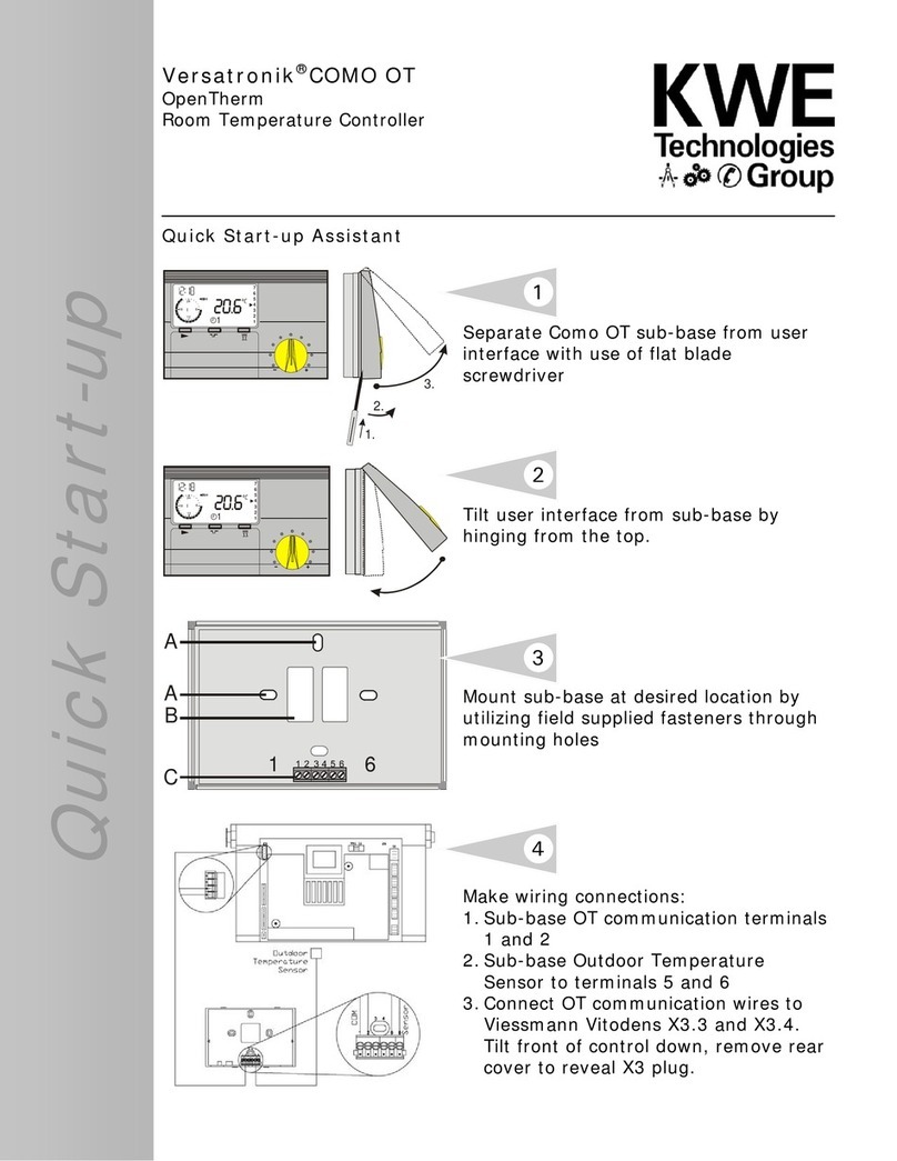
A: Retention holes (for assembly on switch
socket)
B: Cutout for cable entry
C: Connection terminals (PIN 1 is on the left)
1. Secure the base to the wall (approx. at
eye-level).
2. Connect terminals 1+2 on the base with the
terminals on the OT-BUS of the boiler. The
BUS connector is designed to prevent reversed
poling. The connections can be swapped over.
3. Connect the remote telephone switch
[Terminals 3+4],
if required.
4. Connect the outdoor sensor [Terminals 5+6],
if required.
5. Snap on the top part of the controller,
position and hook in at the center of the top
edge, use a little pressure to pivot it down
onto the base and press on.
Connection terminals
PIN 1+2 OT-BUS
PIN 3+4 remote telephone switch
PIN 5+6 outdoor sensor
Disassembly
Insert a screwdriver in the opening on the
underside and lever off. Take hold of the
underside and pivot upwards.
A
C
A
B
16
DBF
2
18 6
12
24
1
2
3
4
5
6
7
F
1
::
1.
2.
3.
DBF
2
18 6
12
24
1
2
3
4
5
6
7
F
1
::
Mounting Wall Base and Room Controller
Section 2.0

9
KWE P/N 542 019 Versatronik COMO OT V1.1 06/2009 Technical information subject to change without notice
1
Outdoor Temperature Sensor Connections
Section 2.1
Control Installation
1. Install outdoor temperature sensor on outside
of structure.
2. Connect field supplied wiring to terminals
inside of sensor. Ensure wiring is run through
strain relief at bottom of sensor housing.
Reinstall sensor cover onto sensor backing.
3. Run field supplied wiring between sensor and
controller sub-base.
4. Locate wiring connections on sub-base of
Versatronik COMO OT Room Controller.
5. Wire to terminals 5 and 6 in sub-base of
Versatronik COMO OT.
Install Versatronik Como OT onto sub-base for
programming or adjustments.
WARNING
!
When extending wire there is the possibility of
exposure to electromagnetic interference. Avoid
running wires beside or near high voltage 120/240
VAC conductors. If proximity to high voltage
conductors cannot be avoided, use stranded, twisted
pair of shield design wire. Ensure that only one end of
the shielding is grounded.
Important
The outdoor temperature sensor should be
mounted 2 to 2.5 metres above ground level on
the north or north-west facing wall of the
building. In the case of multi-storey buildings, it
should be mounted in the upper half of the
second storey. Make sure that the sensor is not
located over windows, doors and air vents, nor
immediately beneath a balcony or guttering. Do
not paint over the outdoor temperature sensor
housing.
Wiring Steps
2
3
4
5

10
KWE P/N 542 019 Versatronik COMO OT V1.1 06/2009 Technical information subject to change without notice
Wiring Room Controller to Viessmann Vitodens 100-W, WB1A
2
3 1
4
5
6
Section 2.2
Control Installation
1. Flip down control of Vitodens 100 boiler. Refer
to the boiler manual outlining procedure.
2. Locate 4 pole plug in upper left hand
corner on backside of control.
3. Wire into 4 terminal plug to terminals 3 and 4.
4. Field supplied wire between boiler and
Versatronik COMO OT Room Controller.
5. Locate wiring connections in sub-base of
Versatronik COMO OT Room Controller.
6. Wire two wire communication wiring into
terminals 1 and 2 of sub-base.
Please note:
If the 4 pole plug referenced in step 2 is missing
from the boiler, please contact your Viessmann
representative or wholesaler.
WARNING
!
When extending wire there is the possibility of
exposure to electromagnetic interference. Avoid
running wires beside or near high voltage 120/240
VAC conductors. If proximity to high voltage
conductors cannot be avoided, use stranded, twisted
pair of shield design wire. Ensure that only one end of
the shielding is grounded.
Wiring Steps

11
KWE P/N 542 019 Versatronik COMO OT V1.1 06/2009 Technical information subject to change without notice
Wiring Room Controller to Viessmann Vitodens 100-W, WB1B
Section 2.2
Control Installation
WARNING
!
When extending wire there is the possibility of
exposure to electromagnetic interference. Avoid
running wires beside or near high voltage 120/240
VAC conductors. If proximity to high voltage
conductors cannot be avoided, use stranded, twisted
pair of shield design wire. Ensure that only one end of
the shielding is grounded.
1. Refer to boiler manual and remove cover from
boiler and set aside.
2. Locate the wiring harness with the 6 pole
terminal block attached.
3. Locate the wire marker denoting terminal 1.
4. If the outdoor temperature sensor has not
been previously installed, the outdoor
temperature sensor can be wired to one of
two locations. It can be wired to the 6 pole
connector from the boiler or directly to the
Versatronik Como OT. If wiring to the Como
wall mounting plate, connect to terminals 5
and 6.
Refer to previous pages regarding the
mounting of the outdoor temperature sensor.
5. Connect Versatronik Como OT to terminals 1
and 2 of the 6 pole termination block from the
Vitodens 100-W, WB1B.
6. Terminate the OT communication wires at the
sub-base of the Versatronik Como OT.
Connect wires to terminals 1 and 2. These
wires are not polarity sensitive.
Installation Instruction
432165
1
2
4
3
4
6
5
4

12
KWE P/N 542 019 Versatronik COMO OT V1.1 06/2009 Technical information subject to change without notice
Remote Telephone Switch Wiring
Section 2.3
Control Installation
1. Wire dry contact (potential free) from switch/
relay/contact.
2. Field supplied wiring between contact and con-
troller sub-base.
3. Wire to terminals 3 and 4.
WARNING
!
When extending wire there is the possibility of
exposure to electromagnetic interference. Avoid
running wires beside or near high voltage 120/240
VAC conductors. If proximity to high voltage
conductors cannot be avoided, use stranded, twisted
pair of shield design wire. Ensure that only one end of
the shielding is grounded.
Wiring Steps
1
2
3
Important
Ensure the contact is potential free. Do not apply
voltage as damage to the controller will occur.

KWE P/N 542 019 Versatronik COMO OT V1.1 06/2009 Technical information subject to change without notice
Control Operation Section 3
Control Operation Overview
Menu Structure Overview
Overview of set value levels menu structure
Overview of user values
Overview if display messages
Section 3.2
Changing the Settings
Enter time and weekday
Enter heating timer programs
Enter holiday program
Section 3.3
Expert Values
Overview of expert values
Overview of code-protected values
Heating curve selection
Explanation of settings
Reset
Section 3.4
Errors
General error list
Error 81
Other error numbers
Communication with the boiler
Unlocking the boiler
Pump runs/runs not
Section 3.5
Section 3.0
Mode Selector Switch
Normal Mode
Party Key
ECO Key
Modifying the set room temperature
Changing the Settings
Section 3.1
Start-up and Commissioning
General error list
Set language
Set time and weekday
Start-up procedure
Switching via telephone
Section 3.6
Technical Data
Section 3.7
Operational Overview Section 3.0

14
KWE P/N 542 019 Versatronik COMO OT V1.1 06/2009 Technical information subject to change without notice
Operation Overview
The Versatronik COMO OT Room Temperature
Control is designed to operate with OpenTherm
enabled boilers to provide efficient operation of
the boiler’s burner. This is achieved by maximizing
burner modulation, instead of demand ON/OFF/ON
operation from standard room thermostats.
The control allows operation with or without an
outdoor temperature sensor. When used without
the sensor, outdoor reset operation is not
possible. As such, some of the settings will not be
available. When the outdoor sensor is installed
and wired to the control,
it is immediately
recognized.
Room temperature
feedback may also be
enabled in an effort to
maximize occupant
comfort. When the
control is programmed
for room temperature
feedback, the room
influence factor
adjustment can be set to
modify the operation/
response of the boiler/
burner. Depending on the
type of heating (eg. Baseboard, panel radiators or
radiant floor), room temperature feedback may
not provide the desired result. This is due to low
mass versus high mass systems and the response
of each system.
When the controller is operating in outdoor reset
mode, it is possible to program the control for up
to three desired normal room temperature
settings. This is based on the timers 1, 2 and 3.
Setting T-Room Des at the same values allows
consistent normal room temperatures from timer
to timer. When the control is not in normal
temperature mode, it operates in reduced mode.
The reduced mode temperature set point can also
be set.
Control Operation
Section 3.0
The slope adjustment operates in conjunction with
the normal mode and reduced mode settings.
Adjustment of the heating slope is based on
providing the heat necessary from the boiler/
system to overcome the heat loss of the structure.
By making adjustments to the slope and room
temperature mode settings, a boiler water
temperature will be calculated. Heating curve
settings of 0.8 and below are generally suited to
lower temperature systems where a setting of 1.0
and above may be better suited for higher water
temperatures. When adjusting the heating curve
from 0.8 to 1.0, there is a 12C/ shift.
The dial on the front of
the control allows the
user to make minor
adjustments, which
effects the end
calculation of boiler water
temperature set point.
Each dot equates to a +/-
1 degree C or 2.5
degrees F.
The pump operation of
the boiler will be guided
by the selection of room
temperature feedback. If
the room feedback is
turned ON, the pump will operate based on
whether the actual room temperature is above or
below the set point. If the actual room
temperature is above the set point value, the
pump will remain off until the room temperature
drops sufficiently to create a call for heat.
If the room feedback is switched off, the pump will
continue to operate until the control enters warm
weather shut down. The warm weather shut down
mode takes place when the out door temperature
is greater than the normal and reduced mode
temperatures. As the outdoor air temperature
drops below the normal and/or reduced room
temperature set points, the pump will again
continue to operate.
Important
DHW production with the Versatronik Como is not
possible unless the boiler supports a DHW
function. With the OpenTherm communications,
the DHW production is possible just as long as the
boiler supports the functionality.

15
KWE P/N 542 019 Versatronik COMO OT V1.1 06/2009 Technical information subject to change without notice
D
F
1
AB
C
EFIGH
D
J
J
(Hinged control cover closed)
ÏÏÏ
Ï
Operating mode selector switch
ECO key (interruption of heating time)
Party key (heating time extension)
Modification of set room temperature
Mode selector switch
Control Operation
Press the key as often as necessary to set the
operating mode required. The selected operating
mode is represented by a symbol in the display.
It takes effect when the selected setting remains
unchanged for 5 sec.
The following operating modes are available for
selection:
iStandby / OFF
(heating OFF, only frost protection function
active)
F1 Automatic mode
(heating according to time program 1)
F2 Automatic mode
(heating according to time program 2)
FSummer mode
(heating OFF, only hot water preparation
active)
hDay mode (Normal mode)
(24 hour heating at comfort temperature 1)
CNight mode (Reduced mode)
(24 h heating at economy temperature)
Display in normal mode
!Due to inertia of the room temperature,
deviations of +/- 1°C/ 2°F to the required
room temperature are normal. During
transition from reduced operation and
heating operation, greater deviations are
possible at times.
A Current time
B Set room temperature (represented in degrees
Celsius)
C Day (1=Monday, 2=Tuesday, ..., =Sunday)
(as shown, 3 = Wednesday)
D Bus symbol (if this symbol does not appear,
check the data cable to the boiler)
E Indicates the active heating program (as
shown 6:00 to 9:00 and 14:00 to 23:00)
F Status indicator: Hburner ON; ZDheating
operation; ZFhot water preparation
G Mode selector switch (as shown F1 =>
Heating according to time program 1)
H Mode indicator and current status (here: BII
=> Heating with set room temperature 2)
I Display of the current room temperature
Section 3.1

16
KWE P/N 542 019 Versatronik COMO OT V1.1 06/2009 Technical information subject to change without notice
B
B
ECO key (heating time interruption)
Displays (for approx. 3 sec.) the set interruption of
the heating time => Heating at economy
temperature [ C]
Use ECO Key to start setting/display / set
duration of heating time interruption
press => + 1 hour for each actuation
press => - 1 hour for each actuation
press 3 seconds:
Heating circuit switches to economy mode
for the rest of the day.
Display switches briefly to "ECO"
End the set ECO function by pressing the Mode
selector switch
Displays (for approx. 3 sec.) the set extension of
the heating time => Heating at comfort
temperature [ B]
Party key (heating time extension)
Use to start setting/display / set
extension of heating time
press => + 1 hour for each actuation
press => - 1 hour for each actuation
press 3 seconds:
Heating circuit heats until the next day.
Display switches briefly to "PARTY"
End the set PARTY function by pressing the Mode
selector switch
Modifying the set room temperature
In Normal mode, the heating system operates
according to the set room temperature (default,
20°C/68 °F )
Use the rotary knob to adjust the set room
temperature by ± 5 °C/9°F . The nighttime
temperature (economy temperature) set on the
controller is not affected.
Turn clockwise => Warmer (~ 1°C/2°F per dot)
Turn counterclockwise => Colder (~ 1°C/2°F per
dot)
Section 3.1
Control Operation

17
KWE P/N 542 019 Versatronik COMO OT V1.1 06/2009 Technical information subject to change without notice
~
ÏÏÏ
ÄProgramming key
a) Select a value level
b) Select a value to be changed
c) Saving the new value
Plus key
(Search for or change value)
Minus key
(Search for or change value)
Changing the Settings
Operating and changing modes are
accessed directly by opening the
control panel cover.
=> USER in the display
/Use the Plus/Minus keys to select the
level in which the value to be changed
is located
=> Overview on the following pages
ÄPress the Prog key => Open / Select the
level
/Use the Plus/Minus keys to locate the
value
=> Overview on the following pages
ÄPress the Prog key => Select the value
Warning triangle appears in the display
=> Value can be changed
/ Use the Plus/Minus keys to change
the value
either => Do not save the value
òClose the control panel cover =>
ECaution! The changed value is not
saved
or => Save the value
ÄPress the Prog key => Value is saved
Warning triangle disappears from the
display and then
òClose the control panel cover
Section 3.1
Control Operation

18
KWE P/N 542 019 Versatronik COMO OT V1.1 06/2009 Technical information subject to change without notice
Menu Structure Overview
ÄProgramming key
a) Select a value level
b) Select a value to be changed
c) Saving the new value
Plus key
(Search for or change value)
Minus key
(Search for or change value)
Section 3.2
Main Menu
User
Display
Time-Date
HTG-PROG1
HTG-PROG2
Expert
Holiday
HotWProg
Expert
Heatslope
Adaption
Room-Infl1
I-Control
N-Opt-Time
Max Opt-Time
Heat Up Opti
User:
T-Room Des1
T-Room Des2
T-Room Des3
T-Reduced
Max Modulati
Max T-HS
T-Absence
Return
C/F
HotWProg
Display:
T-Outside
T-Room
T-DHW
T-HS
Burner Start
Burner Time
Modulation
Return
Water Press
Time-Date Adjust
HTG-Prog2 Adjust
HTG-Prog1 Adjust
Time-Day
Time Selection
Day Selection
T-Room Adjust
Out-Temp-Del
Heatslope 2
Rooms-Infl2
English
Display
20
23
22
21
24
268-04
Return
Control Operation

19
KWE P/N 542 019 Versatronik COMO OT V1.1 06/2009 Technical information subject to change without notice
Overview of levels menu structure
~OPEN cover Îsearch for level using /
Control Operation
Section 3.2
Main Menu
Selections
Page Reference Description
User 18 Selection of base control settings
Display 19 Review of current temperatures
Time-Day 20 Programming of time and day
HTG Prog 1 21 Programming of timer programs
HTG Prog 2 21 Programming of timer programs
Hotwprog N/A
Holiday 23 Programming of holiday programs
Expert 24 Programming of higher level settings

20
KWE P/N 542 019 Versatronik COMO OT V1.1 06/2009 Technical information subject to change without notice
Overview of user values
~OPEN cover Îsearch for level using /
Control Operation
Section 3.2
User Settings Range Default
Value
Description
T-ROOM DES1 5oC – 40oC
41oF – 104oF
20C/68F
T-ROOM DES2 5oC – 40oC
41oF – 104oF
20C/68F
T-ROOM DES3 5oC – 40oC
41oF – 104oF
20C/68F
T-REDUCED 5oC – 40oC
41oF – 104oF
10C/50F T-REDUCED
Set room temperature for the night
T-ABSENCE 5oC – 40oC
41oF – 104oF
15C/59F T-ABSENCE
Set room temperature for the holiday
period
MAX T-HS 30oC –110oC
86oF – 230oF
85C/185F MAX T-HS
Maximum temperature of the boiler in
heating operation:
Limitation for saving energy possible
MAX MODULATI 0—100% 80% MAX MODULATION
Maximum modulation factor of the boiler
in heating operation: Output limitation of
the boiler for saving energy
oC / oF oC - oF C Temperature Selection
RETURN Return to Main Menu
T-ROOM DESIRED1-3
Set room temperature for the 1., 2. or 3.
heating periods
When USER shown in screen, press Ä
Move within User level with / keys
Other manuals for Versatronik COMO OT
1
Table of contents
Other KWE Temperature Controllers manuals
Popular Temperature Controllers manuals by other brands

Panasonic
Panasonic U-8ME1E81 Service manual

oventrop
oventrop Unibox T operating instructions

Honeywell
Honeywell C7650A user manual

Chromalox
Chromalox LIMIT Installation and operating instructions

BriskHeat
BriskHeat BriskONE instruction manual

oventrop
oventrop Regudis W-HTU Installation and operating instructions for the specialised installer