oventrop Regudis W-HTU Operating instructions

Premium Armaturen + Systeme
Temperaturvorhalte-Regelset
für Wohnungsstation „Regudis W- TU“
Einbau- und Betriebsanleitung für den Fachhandwerker
Vor dem Einbau des Temperaturvorhalte-Regel sets
die Einbau- und Betriebsanleitung vollständig lesen!
Die Einbau- und Betriebsanleitung sowie alle mit-
geltenden Unterlagen an den Anlagenbetreiber wei-
tergeben !
Inhalt:
1. Allgemeines...................................................... 1
2. Sicherheitshinweise ......................................... 1
3. Transport, Lagerung, Verpackung ................... 2
4. Technische Daten ............................................ 2
5. Aufbau und Funktion ....................................... 2
6. Einbau und Montage ....................................... 2
7. Betrieb.............................................................. 4
8. Wartung und Pflege ......................................... 4
9. Garantie ........................................................... 4
1. Allgemeines
1.1. Informationen zur Betriebsanleitung
Diese Einbau- und Betriebsanleitung dient dem Fach-
handwerker dazu, das Temperaturvorhalte-Regelset
fachgerecht zu installieren und in Betrieb zu nehmen.
Mitgeltende Unterlagen:
Anleitungen aller Anlagenkomponenten sowie allgemein:
Normen, Vorschriften, Sicherheitsbestimmungen.
1.2. Aufbewahrung der Unterlagen
Diese Betriebsanleitung sollte zum späteren Gebrauch
vom Anlagenbetreiber aufbewahrt werden.
1.3. ymbolerklärung
inweise zur Sicherheit sind durch Symbole gekenn-
zeichnet. Diese inweise sind zu befolgen, um Unfälle,
Sachschäden und Störungen zu vermeiden.
Heiße Oberflächen
Bei Betrieb kann die Verrohrung des Tempera-
turvorhalte-Regelsets, sowie können sämtliche
Einzelteile der Wohnungsstation Regudis W-HTU
die Medientemperatur annehmen. Bei hohen
Medientemperaturen nicht ohne chutzhand-
schuhe anfassen.
D
Eine Übersicht der weltweiten Ansprechpartner
finden Sie unter www.oventrop.de.
Technische Änderungen vorbehalten.
134109080 03/2013
OVENTROP Gmb & Co. KG
Paul-Oventrop-Straße 1
D-59939 Olsberg
Telefon +49 (0)2962 82-0
Telefax +49 (0)2962 82-400
otline +49 (0)2962 82-234
E-Mail mail@oventrop.de
Internet www.oventrop.com
1.4. Urheberschutz
Die Einbau- und Betriebsanleitung ist urheberrechtlich
geschützt.
2. icherheitshinweise
2.1. Bestimmungsgemäße Verwendung
Die Betriebssicherheit ist nur bei bestimmungsgemäßer
Verwendung des Temperaturvorhalte-Regelsets ge -
währ leistet.
Das Temperaturvorhalte-Regelsets ist zum Einbau in
die Wohnungsstation „Regudis W- TU“ bestimmt.
Jede darüber hinausgehende und/oder andersartige
Verwendung des Temperaturvorhalte-Regelsets ist un-
tersagt und gilt als nicht bestimmungsgemäß.
Ansprüche jeglicher Art gegen den ersteller und/oder
seine Bevollmächtigten wegen Schäden aus nicht be-
stimmungsgemäßer Verwendung können nicht aner-
kannt werden.
Zur bestimmungsgemäßen Verwendung zählt auch die
korrekte Einhaltung der Einbau- und Betriebsanleitung.
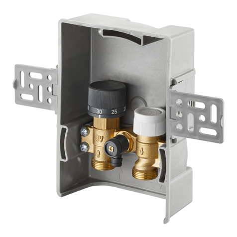
Abb.1 Temperaturvorhalte-Regelset
2.2. Gefahren, die vom Einsatzort ausgehen können
Der Fall eines externen Brandes wurde bei der Ausle-
gung des Temperaturvorhalte-Regelsets nicht berück-
sichtigt.
!
GEFA R weist auf eine un-
mittelbar gefährliche Situation hin, die zum Tod oder
zu schweren Verletzungen führen wird, wenn die
Sicherheitsmaßnahmen nicht befolgt werden.
GEFAHR
!
AC TUNG weist auf mögli-
che Sachschäden hin, welche entstehen können, wenn
die Sicherheitsmaßnahmen nicht befolgt werden.
ACHTUNG
GEFAHR
!
2
1 = ca. 10 °C
2 = ca. 20 °C
3 = ca. 30 °C
4 = ca. 40 °C
5 = ca. 50 °C
6 = ca. 60 °C
7 = ca. 70 °C
Die Teilstriche zwischen
den Ziffern entsprechen
jeweils einer Temperatur-
veränderung von ca. 5 °C
}
Einstellmarke
andgriff
Memo-Scheibe
Position Bezeichnung Anzahl
1 Thermostat 1
2 Ventileinsatz 1
3 Anschlussstück 1
4 Dichtringe 2
5 Rohrgruppe 1
6 Anschlussleitung 1
– Bleiplomben 3
3. Transport, Verpackung und Lagerung
3.1. Transportinspektion
Lieferung unmittelbar nach Erhalt auf mögliche Trans-
portschäden untersuchen.
Falls derartige oder andere Mängel feststellbar sind,
Warensendung nur unter Vorbehalt annehmen. Rekla-
mation einleiten. Dabei Reklamationsfristen beachten.
3.2. Lagerung
Das Temperaturvorhalte-Regelset nur unter folgenden
Bedingungen lagern:
– Nicht im Freien, trocken und staubfrei aufbewah-
ren.
– Keinen aggressiven Medien oder itzequellen aus-
setzen.
– Vor Sonneneinstrahlung und übermäßiger mecha-
nischer Erschütterung schützen.
– Lagertemperatur: -20 bis 55°C,
relative Luftfeuchtigkeit: max. 95 %
– Gegen äußere Gewalt (wie Schlag, Stoß, Vibra-
tion usw.) schützen
– Armaturaufbauten wie andräder, Messventile,
Stellantriebe dürfen nicht zur Aufnahme von äu-
ßeren Kräften, wie z.B. als Anbindungspunkte
für ebezeuge etc. zweckentfremdet werden.
– Es müssen geeignete Transport- und ebemittel
verwendet werden.
4.2. Materialen
Rohre aus Edelstahl, Dichtungen aus EPDM bzw. Fa-
serdichtungen, Ventileinsatzspindel aus nichtrostendem
Stahl, diverse Einzelteile aus Messing.
5. Aufbau und Funktion
5.1. Übersicht / Funktionsbeschreibung
Abb. 2 Wohnungsstation „Regudis W- TU“
vor und nach dem Einbau des Temperaturvorhalte-
Regelsets
Das Temperaturvorhalte-Regelset gewährleistet, dass
auch bei Stillstandzeiten der Wohnungsheizung die
gewünschte Trinkwassertemperatur schnell erreicht
wird. ierzu wird vom Vorlauf des eizwassers eine
geringe Wassermenge in den Rücklauf des eizwas-
sers eingespeist, die nicht von dem evtl. in der Woh-
nungsstation „Regudis W- TU“ eingebauten Wärme-
mengenzähler erfasst wird.
5.2. Anwendungsbereich
Oventrop Temperaturvorhalte-Regelsets werden ein-
gesetzt in Wohnungsstationen „Regudis W- TU“ wenn
die Rohrleitungen von der auptleitung bzw. vom Puf-
ferspeicher zu den einzelnen Wohnungsstationen lang
sind.
6. Einbau und Montage
6.1. Lieferumfang
Kontrollieren Sie das Temperaturvorhalte-Regelset vor
dem Einbau auf Vollständigkeit und auf mögliche
Transportschäden.
Abb. 3 Temperaturvorhalte-Regelset
4. Technische Daten
4.1. Leistungsdaten
Sollwertbereich: 10-70°C
ACHTUNG

3
6.2. Montage
1. Alle Kugelhähne absperren.
2. Die gesamte Wohnungsstation „Regudis W- TU“
entleeren. (z.B. mit ilfe des Entleerungsstopfens
Abb. 4)
Ausbau der Einzelteile aus der W hnungsstati n
Abb. 4 Ausbau der Einzelteile
Abb. 5 Einbau – Teil 1
3. Die Blindstopfen (SW 22) aus dem Edelstahlver-
teiler herausschrauben.
Es können noch Wasserreste austreten.
4. Mit einem Inbusschlüssel (SW 5) die Schrauben an
der Kunststoffschelle lösen und den vorderen
Schellenkörper abnehmen. Dann die Überwurfmut-
ter (SW 30) des Rohres lösen und das Rohr aus
der Station entfernen.
Einbau des Temperaturv rhalte-Regelsets
5. Die Rohrgruppe in der Wohnungsstation „Regudis
W- TU“ wie in Abb. 5 angegeben positionieren
und mit neuen Dichtringen wieder festschrauben
(SW 30). Dabei alle Überwurfmuttern der Rohr-
gruppe fest anziehen. Den Schellenkörper wieder
auf das Rohr setzen und die Schrauben mit ilfe
eines Inbusschlüssels (SW 5) wieder anziehen.
6. Das Anschlussstück (SW 27) von oben in den Edel-
stahlverteiler, wie in Abb. 5 gezeigt, fest einschrau-
ben.
7. Den Ventileinsatz (SW 19) von unten in den Edel-
stahlverteiler fest einschrauben.
Abb. 6 Einbau – Teil 2
8. Thermostat (SW 32) zunächst auf ’6’ stellen und
so ausrichten, dass die Markierung (bei Schriftzug
Oventrop) gut sichtbar ist. Thermostat in dieser
Stellung festhalten und die Überwurfmutter fest auf
den Ventileinsatz aufschrauben. Anschließend mit
der Anschlussleitung, SW 8, das Anschlussstück
und die Rohrgruppe verbinden.
9. Nach der Montage sind die Wohnungsstation „Re-
gudis W- TU“, das Temperaturvorhalte-Regelset
und speziell alle Montagestellen auf Dichtheit zu
überprüfen!
A. Rohrgruppe, bzw. Überwurfmutter des oberen Roh-
res, und Wärmemengenzähler plombieren.
B. Überwurfmuttern der beiden Rohre (bei der An-
schlussleitung) plombieren.
C. Rohrgruppe, bzw. Überwurfmutter des unteren
Rohres mit dem Kugelhahn plombieren.
Verpl mben der R hrgruppe
Abb. 7 Möglichkeiten zur Plombierung
Bei der Montage dürfen keine Fette oder Öle ver-
wendet werden. Diese können Ventildichtungen
zerstören. Schmutzpartikel sowie Fett und Ölreste
sind ggf. aus den Zuleitungen herauszuspülen.
Bei der Auswahl des Betriebsmediums ist der all-
gemeine Stand der Technik zu beachten (z.B. VDI
2035).
Blindstopfen
Thermostat
SW 32
Blindstopfen
SW 30
SW 22
SW 19
SW 27
SW 30
Anschlussstück
Ventileinsatz
Entleerungs-
stopfen
ACHTUNG
ACHTUNG

4
7. Betrieb
7.1. Einstellung Vorhaltefunktion
Durch die Einstellung am Thermostatkopf wird eine
Mindestwasserumlaufmenge im eizkreis geregelt.
Steigt die Warmwassertemperatur bei einer Zapfung
zu langsam an, kann der Thermostatkopf höher ein-
gestellt werden.
7.2. Begrenzen des Einstellbereichs
Die Temperaturwerte lassen sich wie folgt begrenzen
bzw. blockieren:
Abb. 11: Innerhalb des Hand-
griffes befinden sich zwei Clipse
in „Parkposition“, so wie abge-
bildet. Sie sind nach außen he-
rauszuziehen. (Selbstverständ-
lich können die Clipse bei
Nichtbenutzung auch wieder in
diese „Parkposition“ zurückge-
steckt werden.)
Abb. 11
Abb. 12: Zur unteren Begren-
zung des Einstellbereiches, z. B.
auf Merkzahl „2“ (entspricht ca.
20 °C), wird ein Clip wie abge-
bildet in die Position eine Nut
vor der Merkzahl „2“ einge-
steckt. (Die Nut direkt gegen-
über der Merkzahl „2“ bleibt
also frei.)
Abb. 12
Abb. 13: Zur oberen Begren-
zung des Einstellbereiches, z. B.
auf Merkzahl „4“ (entspricht ca.
40 °C), wird der zweite Clip in
die Position eine Nut nach der
Merkzahl „4“ eingesteckt. (Die
Nut direkt gegenüber der Merk-
zahl „4“ bleibt also frei.)
Abb. 13
Abb. 14: Den Handgriff so auf-
stecken, dass die Merkzahl „3“
auf dem Handgriff gegenüber
der Einstellmarke liegt.
Abb. 14
Abb. 15: Mit dem Handballen
kräftig gegen den Handgriff
drücken oder gegenschlagen,
bis er einrastet. Der Einstellbe-
reich des Thermostaten ist nun
begrenzt. Es lassen sich jetzt
nur Werte zwischen den Merk-
zahl „2“ und „4“ (ca. 20 °C -
40 °C) einstellen.
Abb. 15
Abb. 9: Handgriff mit Hilfe des
Werkzeuges (Art.-Nr. 198 91 00)
oder eines Stiftes, z. B. dem
Druckknopf eines Kugelschrei-
bers abziehen. Den Stift dazu
in das Demontageloch auf der
Unterseite des Thermostaten
stecken. Durch Drehen des
Handgriffes in die Schließstel-
lung kann dieser leicht gelöst
werden.
Abb. 9
Abb. 10: Nach Abziehen des
Handgriffes: Fühlerhalter nach
links drehen, bis die weiße Jus-
tiermarkierung auf die Einstell-
marke zeigt.
Abb. 10
6.3. Einbaubeispiele
Abb. 8 Einbau von zwei Wohnungsstationen
„Regudis W- TU“
Einbau von zwei Wohnungsstationen „Regudis W- TU“,
wobei in der Wohnungsstation der oberen Etage das
Temperaturvorhalte-Regelset eingebaut ist.
8. Wartung und Pflege
Bei Funktionsstörungen sind Wartungsarbeiten erfor-
derlich.
9. Garantie
Es gelten die zum Zeitpunkt der Lieferung gültigen
Garantiebedingungen der Fa. Oventrop
Einstellmarke
Justiermarkierung
Fühlerhalter

5
Valves, controls + systems
Derivative temperature control set
for dwelling station “Regudis W- TU”
Installation and operating instructions for the specialised installer
Read installation and operating instructions care-
fully before installing the derivative temperature
control set!
The installation and operating instructions as well
as all other valid documents have to remain with
the user of the system !
Content:
1. General information .......................................... 5
2. Safety notes...................................................... 5
3. Transport, packaging and storage ................... 6
4. Technical data................................................... 6
5. Construction and function................................ 6
6. Installation......................................................... 6
7. Operation.......................................................... 8
8. Maintenance ..................................................... 8
9. Warranty............................................................ 8
1. General information
1.1. Information regarding installation and opera -
ting instructions
These installation and operating instructions serve the
installer to install the derivative temperature control
set professionally and to set it into operation.
Other valid documents:
Manuals of all system components as well as valid
standards, regulations and safety regulations.
1.2. Keeping of documents
These installation and operating instructions should
be kept by the user of the system.
1.3. ymbol explanation
Safety guidelines are displayed by symbols. The guide-
lines are to be observed to prevent accidents, damage
to property and malfunctions.
Hot surfaces
The piping of the derivative temperature control
set as well as all components of the dwelling
station “Regudis W-HTU” can get very hot dur-
ing operation. Do not touch without safety
gloves.
GB
For an overview of our global presence visit
www.oventrop.com.
Subject to technical modifications.
134109080 03/2013
1.4. Copyright
The installation and operating instructions are copy-
righted.
2. afety notes
2.1. Correct use
Operating safety is only guaranteed if the derivative
temperature control set is used correctly.
The derivative temperature control set is designed for
the installation in the “Regudis W- TU“ dwelling sta-
tion.
Any use of the derivative temperature control set out-
side the above circumstances will be considered as
non-compliant and misuse.
Claims of any kind against the manufacturer and/or
its authorised representatives due to damages caused
by incorrect use cannot be accepted.
The observance of the installation and operating in-
structions is part of the compliance terms.
Illustr.1 Derivative temperature control set
2.2. Possible dangers at the installation location
The case of an external fire has not been taken into
consideration during the design of the derivative tem-
perature control set.
!
DANGER indicates an immi-
nent dangerous situation which will lead to death or
serious injury if the safety guidelines are not obser-
ved.
DANGER
!
ATTENTION indicates a
possible damage to property which may occur if the
safety guidelines are not observed.
ATTENTION
DANGER
!

6
1 = about 10 °C
2 = about 20 °C
3 = about 30 °C
4 = about 40 °C
5 = about 50 °C
6 = about 60 °C
7 = about 70 °C
The minor graduations between
the figures represent a change
of room temperature of about
5 °C.
}
Indicator mark
andgrip
Memory disc
Position Designation Number
1 Thermostat 1
2 Valve insert 1
3 Connection piece 1
4 Ring gaskets 2
5 Pipe group 1
6 Connection pipe 1
– Lead seals 3
3. Transport, packaging and storage
3.1. Transport inspection
Upon receipt, check delivery for any damages caused
during transit.
Any damages must be reported immediately upon re-
ceipt.
3.2. torage
The derivative temperature control set must only be
stored under the following conditions:
– Do not store in open air, keep dry and free from
dust.
– Do not expose to aggressive fluids or heat sources.
– Protect from direct sunlight and mechanical agita-
tion.
– Storage temperature: -20 up to +55°C,
max. relative humidity of air: 95 %
– Please protect against external forces (e.g.
impacts, vibrations etc.)
– External components such as handwheels,
pressure test points and actuators should not
be used as lever points during installation.
– Suitable means of transport and lifting devices
have to be used.
4.2. Materials
Pipes made of stainless steel, seals made of EPDM or
fibre seals, valve insert stem made of stainless steel,
various single components made of brass.
5. Construction and function
5.1. ummary / Functional description
Illustr. 2 Dwelling station “Regudis W- TU“ before and
after installation of the derivative temperature control
set
The derivative temperature control set ensures that
the required potable water temperature is achieved
quickly even when the heating installation of the
dwelling is not in operation.
To achieve this, a small amount of heating water is
circulated via a capillary from the heating flow to the
return to maintain heat at the “Regudis W- TU”. This
small bypass is not measured by the heat meter.
5.2. Application
The Oventrop derivative temperature control sets are
installed in the dwelling stations “Regudis W- TU” if
the pipework from the main pipe towards the buffer
tank or the individual dwelling stations is too long.
6. Installation
6.1. Extent of supply
Upon receipt, check the delivery for completeness
and any damages caused during transit.
Illustr. 3 Derivative temperature control set
4. Technical data
4.1. Performance data
Temperature range: 10-70°C
ATTENTION

7
6.2. Installation
1. Close off all ball valves.
2. Drain off the complete dwelling station “Regudis
W- TU” (for instance with the help of the draining
plug illustr. 4)
Rem val f the single c mp nents fr m the
dwelling stati n
Illustr. 4 Removal of single components
Illustr. 5 Installation – Part 1
3. Unscrew blind plug (spanner size 22) from the stain-
less steel distributor.
Water may escape.
4. Loosen the screws of the plastic clamp with a 5
mm Allen key and remove the front part of the
clamp. Now loosen the collar nut (spanner size 30)
of the pipe and remove the latter from the station.
Installati n f the derivative temperature
c ntr l set
5. Position the pipe group in the dwelling station
“Regudis W- TU” as shown in illustration 5 and
fasten it with new ring gaskets (spanner size 30).
Tighten all collar nuts of the pipe group firmly. Repo-
sition the front part of the clamp onto the pipe and
tighten the screws with a 5 mm Allen key.
6. Screw connection piece (spanner size 27) into the
stainless steel distributor from the top, as shown
in illustration 5.
7. Screw valve insert (spanner size 19) into the stain-
less steel distributor from below.
Illustr. 6 Installation – Part 2
8. Set thermostat to position ’6’ and align so that the
mark (close to inscription OVENTROP) is well visi-
ble. old thermostat in this position and screw col-
lar nut (spanner size 32) onto the valve insert. Now
connect the connection piece and the pipe group
with the help of the connection pipe (spanner size 8).
9. After installation, check dwelling station “Regudis
W- TU”, derivative temperature control set and all
installation points for leaks!
A. Lead lock pipe group or collar nut of the upper
pipe and heat meter.
B. Lead lock collar nuts of both pipes (of the connec -
ting pipe).
C. Lead lock pipe group or collar nut of the lower pipe
with the ball valve.
Lead l cking f the pipe gr up
Illustr. 7 Possibilities for lead locking
Do not use any lubricant or oil during installation
as these may destroy valve seals. If necessary, all
dirt particles and lubricant or oil residues must be
removed from the pipework by flushing the latter.
When choosing the operating fluid, the latest tech-
nical development has to be considered (for in-
stance VDI 2035).
Thermostat
SW* 32
* SW = spanner size
Blind-plug
Blind-plug
SW* 30
SW 22
Draining-plug
SW* 19
SW 27*
SW* 30
Connection piece
Value insert
ATTENTION
ATTENTION

8
7. Operation
7.1. etting of the derivative function
Control of a minimum water circulation in the heating
circuit is carried out by setting the thermostat to the
corresponding value. If the hot water temperature in-
creases too slowly when drawing off water, the ther-
mostat can be set to a higher value.
7.2. Limiting the control range
The control range of the thermostat can be limited as
follows:
Illustr. 11: On the inner side of
the handgrip you will find two
clips in the “parking” position.
They should be removed by sli-
ding them outward. (When not
in use, the clips may be put
back into the “parking” posi-
tion.)
Illustr. 11
Illustr. 12: To limit the minimum
control range, e.g. at figure “2“
(equals about 20 °C), one clip
should be fitted into the groove
immediately before figure “2”.
(The groove directly opposite
figure “2” thus remains free.)
Illustr. 12
Illustr. 13: To limit the maximum
control range, e.g. at figure “4”
(equals about 40 °C), the second
clip should be fitted into the
groove immediately after figure
“4”. (The groove directly oppo-
site figure “4” thus remains
free.)
Illustr. 13
Illustr. 14: Replace the handgrip
so that figure “3” is in line with
the indicator mark.
Illustr. 14
Illustr. 15: Push down handgrip
by hand to secure. The control
range of the thermostat is now
limited and you can only set
values between figure “2” and
“4” (about 20 °C - 40 °C).
Illustr. 15
Illustr. 9: Remove the hand-grip
with the tool (Item no. 198 91 00)
or with a pin, e.g. with the push
button of a pen. Insert the
tool/pin in the hole provided on
the lower side of the thermo-
stat. By turning the handgrip to
the shut-off position, it is easily
removed.
Illustr. 9
Illustr. 10: After having removed
the handgrip: Turn the sensor
casing to the left until the white
calibration mark is in line with
the indicator mark.
Illustr. 10
6.3. Installation examples
Illustr. 8 Installation of two dwelling stations
“Regudis W- TU“
Installation of two dwelling stations “Regudis W- TU“
with the derivative temperature control set being in-
stalled in the dwelling station in the upper storey.
8. Maintenance
If malfunctions occur, the derivate temperature control
set has to be serviced.
9. Warranty
Oventrops warranty conditions valid at the time of
supply are applicable.
Indicator mark
Calibration mark
Sensor casing

9
Robinetterie «haut de gamme» + Systèmes
Set de bypass thermostatisé à consigne de température réglable
pour station d’appartement «Regudis W- TU»
Notice d’installation et d’utilisation pour le professionnel
Lire intégralement la notice d’installation et d’utili-
sation avant le montage du set de bypass ther-
mostatisé à consigne de température réglable!
Remettre la notice d’installation et d’utilisation ainsi
que tous les documents de référence à l’utilisateur
de l’installation !
Contenu:
1. Généralités....................................................... 9
2. Consignes de sécurité ..................................... 9
3. Transport, emballage et stockage ................... 10
4. Données techniques........................................ 10
5. Construction et fonctionnement...................... 10
6. Installation et montage .................................... 10
7. Réglage de service .......................................... 12
8. Entretien........................................................... 12
9. Garantie............................................................ 12
1. Généralités
1.1. Informations sur la notice d’installation
Cette notice d’installation et d’utilisation a pour but
d’aider le professionnel d’installer et mettre en service
le set de bypass thermostatisé à consigne de tempé-
rature réglable.
Autres documents de référence:
Notices de tous les composants du système.
1.2. Conservation des documents
Cette notice d’installation et d’utilisation doit être
conservée par l’utilisateur de l’installation pour réfé-
rence ultérieure.
1.3. Explication des symboles
Les consignes de sécurité sont identifiées par des
symboles. Ces consignes doivent être respectées pour
éviter des accidents, des dégâts matériels et des dys-
fonctionnements.
urfaces chaudes
En pleine période de service, le tubage du set
de bypass thermostatisé à consigne de tem-
pérature réglable ainsi que tous les compo-
sants de la station d’appartement «Regudis W-
HTU» peuvent devenir très chauds. Ne pas
toucher sans gants de protection.
F
Vous trouverez une vue d’ensemble des interlocu-
teurs dans le monde entier sur www.oventrop.com.
Sous réserve de modifications techniques.
134109080 03/2013
1.4. Protection de la propriété intellectuelle
La présente notice d’installation et d’utilisation est
protégée par le droit de la propriété intellectuelle.
2. Consignes de sécurité
2.1. Utilisation correcte
La sureté de fonctionnement du set de bypass ther-
mostatisé à consigne de température réglable n’est
garantie que s’il est affecté à l’utilisation prévue.
Le set de bypass thermostatisé à consigne de tempé-
rature réglable est destiné au montage dans les sta-
tions d’appartement «Regudis W- TU» (Réf. 1341030
/ 1341031 / 1341032).
Toute utilisation différente du set de bypass thermos-
tatisé à consigne de température réglable est interdite
et réputée non conforme.
Les revendications de toute nature à l’égard du fabri-
cant et/ou ses mandataires pour des dommages ré-
sultant d’une utilisation non conforme ne seront pas
acceptées.
L’utilisation conforme comprend aussi l’observation
correcte de la notice d’installation et d’utilisation.
Fig.1 Set de bypass thermostatisé à consigne de tem-
pérature réglable
2.2. Risques liés au lieu d’installation
Le cas d’un incendie n’a pas été pris en considération
lors de la conception du set de bypass thermostatisé
à consigne de température réglable.
!
DANGER Risque immédiat de blessu-
res ou de mort!
!
ATTENTION Situation éventuellement
dangereuse pour le produit, l’installation ou l’environ-
nement!
AVERTI EMENT
!
IMPORTANT!
Informations et indications utiles!

10
1 = environ 10 °C
2 = environ 20 °C
3 = environ 30 °C
4 = environ 40 °C
5 = environ 50 °C
6 = environ 60 °C
7 = environ 70 °C
es graduations entre les
chiffres correspondent à une
modification de la température
d’environ 5 °C.
}
Repère
Poignée manuelle
Pastille mémoire
Position Désignation Nombre
1 Thermostat 1
2 Mécanisme 1
3 Pièce de raccordement 1
4 Joints 2
5 Groupe de tuyauterie 1
6 Conduite de raccordement 1
– Plombs 3
3. Transport, emballage et stockage
3.1. Inspection après transport
Examiner la livraison immédiatement après réception
pour vérifier l’absence de dommages dus au trans-
port.
Si des dommages ou d’autres défauts sont constatés,
n’accepter la marchandise que sous réserve. Emettre
une réclamation en respectant les délais applicables.
3.2. tockage
Ne stocker le set de bypass thermostatisé à consigne
de température réglable que dans les conditions sui-
vantes:
–
Pas en plein air: conserver dans un lieu sec et propre.
– Ne pas exposer à des agents agressifs ou à des
sources de chaleur.
– Protéger contre le rayonnement solaire et les vibra-
tions mécaniques excessives.
– Température de stockage: -20°C à +55°C,
humidité relative d’air: 95 % max.
– Protéger le set de bypass thermostatisé à
consigne de température réglable contre des
influences extérieures (chocs, secousses, vibra-
tions etc.).
– Les accessoires de robinetterie tels que volants,
prises de pression, moteurs ne doivent pas être
utilisés comme point d’attache pour des engins
de levage etc.
– Utiliser des moyens de transport et de levage
appropriés.
4.2. Matériaux
Tubes en acier inoxydable, joints en EPDM ou fibres,
tige du mécanisme en acier inoxydable, composants
divers en laiton.
5. Construction et fonctionnement
5.1.
Vue d’ensemble / Description du fonctionnement
Illustr. 2 Station d’appartement «Regudis W- TUW»
avant et après le montage du set de bypass ther-
mostatisé à consigne de température réglable
Le set de bypass thermostatisé à consigne de tempé-
rature réglable assure que la température d’eau pota-
ble désirée est atteinte rapidement même pendant les
périodes d’inactivité de l’installation de chauffage de
l’appartement.
Pour y parvenir, une petite quantité d’eau de l’aller
chauffage qui n’est pas enregistrée par le compteur
de calories dans la station d’appartement «Regudis
W- TU», est rajoutée au retour chauffage.
5.2. Domaine d’application
Les sets de bypass thermostatisé à consigne de tem-
pérature réglable Oventrop se montent sur les stations
d’appartement «Regudis W- TU» si la tuyauterie par-
tant de la conduite principale ou du ballon tampon en
direction des stations d’appartement est trop longue.
6. Installation et montage
6.1. Fourniture
Avant le montage, contrôler que le set de bypass ther-
mostatisé à consigne de température réglable est com-
plet et ne présente pas de dommages dus au trans-
port.
Set de bypass thermostatisé à consigne de tempéra-
ture réglable
4. Données techniques
4.1. Caractéristiques
Plage de réglage: 10 – 70°C
ATTENTION

11
6.2. Montage
1. Fermer tous les robinets à tournant sphérique.
2. Vidanger la station d’appartement «Regudis W-
TU» complète (par ex. à l’aide du bouchon de vi-
dange fig. 4).
Dém ntage des c mp sants de la stati n
d’appartement
Fig. 4 Démontage des composants
Fig. 5 Montage – 1ière partie
3. Dévisser les bouchons (clé de 22) du distributeur
en acier inoxydable.
De l’eau peut encore s’échapper.
4. 1. Libérer les vis du collier plastique à l’aide d’une
clé six pans de 5 mm et démonter la partie avant
du collier. Ensuite, desserrer l’écrou d’accouple-
ment (clé de 30) du tube et démonter ce dernier de
la station.
M ntage du set de bypass therm statisé à
c nsigne de température réglable
5. Positionner le groupe de tuyauterie dans la station
d’appartement «Regudis W- TU» comme illustré
sur la fig. 5 et le resserrer avec les nouveaux joints
en serrant tous les écrous d’accouplement solide-
ment. Remonter la partie avant du collier sur le
tube et revisser les écrous à l’aide d’une clé six
pans de 5 mm.
6. Visser à fond la pièce de raccordement (clé de 27)
dans le distributeur par le bas comme illustré sur la
fig. 5.
7. Visser à fond le mécanisme (clé de 19) dans le dis-
tributeur en acier inoxydable par le haut.
Fig. 6 Montage – 2ième partie
8. D’abord régler le thermostat sur la position «6» et
aligner de manière à ce que le marquage (près de
l’inscription OVENTROP) soit bien visible. Tenir le
thermostat dans cette position et visser l’écrou d’ac-
couplement (clé de 32) solidement sur le méca-
nisme. Ensuite, relier la pièce de raccordement avec
le groupe de tuyauterie à l’aide de la conduite de
raccordement, clé de 8.
9. Après le montage, contrôler l’étanchéité de la sta-
tion d’appartement «Regudis W- TU», du set de
bypass thermostatisé à consigne de température
réglable et de tous les points de montage!!
A.
Plomber le groupe de tuyauterie ou l’écrou d’accou-
plement du tube haut avec et le compteur de calories.
B. Plomber les écrous d’accouplement des deux
tubes (de la conduite de raccordement).
C. Plomber le groupe de tuyauterie ou l’écrou d’ac-
couplement du tube bas avec le robinet à tournant
sphérique.
Pl mbage du gr upe de tuyauterie
Fig. 7 Possibilités de plombage
Ne pas utiliser des graisses ou huiles lors du mon-
tage, celles-ci peuvent endommager les joints du
robinet. Si nécessaire, des impuretés ou résidus de
graisse ou d’huile doivent être enlevés de la tuyau-
terie par rinçage.
Choix du fluide de service selon la technologie ac-
tuelle (par ex. VDI 2035).).
Thermostat
Clé plate
de 32
Bouchon
Bouchon
Bouchon de
vidange
Pièce de raccordement
Mécanisme
Clé plate
de 30
Clé plate de 27
Clé plate de 30
Clé plate
de 19
SW 22
ATTENTION
ATTENTION

12
7. Réglage de service
7.1. Réglage de la fonction bypass
Un débit minimal dans le circuit de chauffage est réglé
à l’aide de le tête thermostatique. Si la température
d’eau chaude augmente trop lentement pendant le
puisage, il est possible d’augmenter la température à
l’aide du thermostat.
7.2. Réglage de la température
La température désirée, qui devrait toujours être dis-
ponible dans le circuit de chauffage de la station d’ap-
partement «Regudis W- TU», peut être réglée à l’aide
du thermostat.
7.3. Limitation de la plage de réglage
La température peut être limitée comme suit:
Fig. 11: A l’intérieur de la poi-
gnée manuelle se trouvent
deux clips en «position d’at-
tente» - comme sur la photo -
que vous pouvez retirer. ( es
clips, s’ils ne sont pas utilisés,
peuvent bien sûr être remis en
«position d’attente».)
Fig. 11
Fig. 12: Pour limiter la valeur
de consigne inférieure, par ex.
sur chiffre «2» (environ 20 °C),
faire glisser un clip dans la ner-
vure devant le chiffre «2» com-
me sur la photo. ( a nervure
en face du chiffre «2» reste li-
bre.)
Fig. 12
Fig. 13: Pour limiter la valeur
de consigne supérieure, par ex.
sur chiffre «4» (environ 40 °C),
faire glisser le deuxième clip
dans la nervure derrière le chif-
fre «4». ( a nervure en face du
chiffre «4» reste libre.)
Fig. 13
Fig. 14: Repositionner la poi-
gnée manuelle pour que le chif-
fre «3» soit en face du trait de
repère.
Fig. 14
Fig. 15: Pousser avec la paume
de la main la poignée manuelle
pour l’enclencher. a plage de
réglage du thermostat est ainsi
limitée. e réglage est mainte-
nant limité de «2» à «4» sur la
poignée (environ 20 °C – 40
°C).
Fig. 15
Fig. 9: Retirer la poignée ma-
nuelle à l’aide de l’outil (réf.
198 91 00) ou une pointe, par
ex. l’embout d’un stylo. Enfoncer
la pointe dans le trou sur la
face inférieure du thermostat
et par une simple rotation de
la poignée manuelle en position
«fermée», on retire facilement
la poignée.
Fig. 9
Fig. 10: Après avoir retiré la poi-
gnée manuelle, tourner le sup-
port du capteur à dilatation vers
la gauche jusqu’à ce que le mar-
quage d’ajustage blanc soit en
face du trait de repère.
Fig. 10
6.3. Exemples de montage
Fig. 8 Montage de deux stations d’appartement
«Regudis W- TU»
Montage de deux stations d’appartement «Regudis
W- TU», le set de bypass thermostatisé à consigne
de température réglable est installé dans la station
d’appartement dans l’étage supérieur.
8. Entretien
Le set de bypass thermostatisé à consigne de tempé-
rature réglable doit être entretenu en cas de dysfonc-
tionnements.
9. Garantie
Les conditions de garanties valables au moment de la
livraison sont à appliquer.
Repère
Marquage
d’ajustage
Support du
capteur à
dilatation

13
Üstün kaliteli armatürler ve sistemler
Sıcaklık Kontrol Seti
Regudis W-HTU Daire İstasyonu için
Uzman personel için montaj ve kullanma talimatı
Sıcaklık Kontrol Seti’ni tesis etmeden önce montaj
ve işletme talimatının tümü okunmalıdır!
Montaj ve işletme talimatı ve tüm beraberindeki
evraklar tesis işletmecisine verilmelidir!
İçindekiler:
1. Genel...............................................................13
2. Güvenlik notları ...............................................13
3. Nakliye, Depolama, Ambalaj .......................... 14
4. Teknik veriler .................................................. 14
5. Bileşenler ve işlev........................................... 14
6. ontaj ve tesis etme ...................................... 14
7. İşletim ..............................................................16
8. Bakım ve temizlik ........................................... 16
9. Garanti ........................................................... 16
1. Genel
1.1. İşletme talimatına yönelik bilgiler
Bu montaj ve işletme talimatı Sıcaklık Kontrol Seti’nin
tesisatçı tarafından doğru tesis edilmesine ve işletmeye
alınmasına hizmet etmektedir.
Bu talimat ile birlikte geçerli olan belgeler:
Sistemi oluşturan tüm elemanlar ile ilgili talimatlar.
1.2. Belgelerin muhafaza edilmesi
Bu işletme talimatı ileride kullanılmak üzere işletmeci
tarafından muhafaza edilmelidir.
1.3. Sembollerin tanımı
Güvenlik ile ilgili notlar semboller ile işaretlenmiştir.
Bu notlar kaza, mal tahribatı ve arızaları önlemek için
dikkate alınmalıdır.
Sıcak yüzeyler
İşletme esnasında Sıcaklık Kontrol Seti borusu
ve „Regudis W-HTU” daire istasyonu ve boru
hatları aşırı ısınabilir. üksek ortam sıcaklıkla-
rında koruyucu eldiven takılmalı ve çalışmalara
başlamadan önce sistem kapatılmalıdır.
TR
www. oventrop.com adresinde dünya genelinde
ulaşabileceğiniz adreslerimizi bulabilirsiniz.
Teknik değişiklik hakkı saklıdır.
134109080 03/2013
1.4. Telif hakkı
ontaj ve işletme talimatının telif hakkı saklıdır.
2. Güvenlik notları
2.1. Amaca uygun kullanım
İşletme emniyeti, Sıcaklık Kontrol Seti amaca uygun
kullanıldığında güvence altındadır.
Sıcaklık Kontrol Seti, “Regudis W-HTU” daire istasyo-
nuna (Sipariş No. 1341030 / 1341031 / 1341032) monte
edilmek üzere tasarlanmıştır.
Sıcaklık Kontrol Seti’nin bunu aşan ve/veya bunun
dışında bir kullanımı yasaktır ve amaca uygun kullanım
değildir.
Amaca uygun olmayan kullanım sonucu meydana gelen
zararlardan üretici ve/veya vekillerinden herhangi bir
talepte bulunulamaz.
Amaca uygun kullanıma, montaj ve işletme talimatında
yer alan hususların yerine getirilmesi de girmektedir.
Resim 1. Sıcaklık Kontrol Seti
2.2. Montaj konumundan dolayı ortaya çıkabilecek
tehlikeler
Harici bir yangın olasılığı Sıcaklık Kontrol Seti tasarı-
mında dikkate alınmamıştır.
!
Beden ve yaşam için doğrudan tehlike!
TEHLİKE!
!
Ürün, sistem ve çevre için
tehlikeli durum söz konusu!
TEHLİKE!
!
NOT!
Yararlıbilgilervenotlar!

14
1 = yaklaşık 10 °C
2 = yaklaşık 20 °C
3 = yaklaşık 30 °C
4 = yaklaşık 40 °C
5 = yaklaşık 50 °C
6 = yaklaşık 60 °C
7 = yaklaşık 70 °C
Rakamlar arasındaki
çizgiler yaklaşık 5 °C
sıcaklık değişikliğine
karşı gelmektedir.
}
Referans işareti
Volan
Hafıza pulu
Pozisyon Tanim iktar
1 Termostat 1
2 Vana çedirdeği 1
3 Bağlantı parçası 1
4 Contalar 2
5 Boru grubu 1
6 Kılcal boru 1
– Kurşun mühürler 3
3. Nakliye, ambalaj ve depolama
3.1. Nakliye sonrası kontrol
Gönderi teslim alındıktan hemen sonra nakliye esna-
sında bir hasarın meydana gelip gelmediği tespiti için
kontrol edilmelidir.
Eğer buna benzer veya başka bir hasar tespiti yapılır
ise malzeme şerh koyularak teslim alınmalıdır. Tutanak
tutulmalı ve şikayet yetkili mercilere iletilmelidir.
Burada şikayet sürelerinin aşılmaması dikkate alınma-
lıdır.
3.2. Depolama
Sıcaklık Kontrol Seti aşağıda belirtilen şartlarda depol-
anmalıdır:
– Açık havada olmayacak şekilde kuru ve tozsuz or-
tamda muhafaza edilmelidir.
– Agresif akışkan veya ısı kaynağına maruz bırakıl-
mamalıdır.
– Güneş ışınlarına karşı ve aşırı mekanik sarsıntılara
karşı korunmalıdır.
– Depolama sıcaklığı: -20 ile 55 °C arası.
Bağıl nem oranı: azami % 95.
– Darbe, titreşim vs. gibi dışarıdan gelebilecek şid-
detlere karşı koruyun.
– Volan, ölçüm vanaları, servo tahrikler gibi arma-
tür üzerinde yer alan parçalar kuvvet almak için
(örn. kaldıraçların bağlantı noktası gibi işler için
amaç dışı) kullanılmamalıdır.
– Uygun taşıma ve kaldırma araçları kullanılmalı-
dır.
4.2. Malzemeler
Borular paslanmaz çelik, contalar EPD veya elyaf
conta, kompakt ventil mili paslanmaz çelik, diğer par-
çalar pirinçten.
5. Bileşenler ve işlev
5.1. Genel bakış / Çalışma prensibi
Resim 2. “Regudis W-HTU“ Daire istasyonu, Sıcaklık
Kontrol Seti’ni takmadan önce ve taktıktan sonra
Sıcaklık Kontrol Seti; ısıtma devresinin sıcaklığını kul-
lanma suyunu ısıtmadan sabit tutar.
Bu da lejyonella bakterilerinin üremesinin engellenme-
sinin güvencesidir.
Sıcaklık Kontrol Seti yardımı ile ayrıca ısıtma dönemleri
dışında da sıcak kullanma suyunun hızlı hazır olması
sağlanır.
5.2. Kullanım alanı
Oventrop Sıcaklık Kontrol Seti, “Regudis W-HTU” daire
istasyonlarında, boru hatları ana boru hattına veya akü-
mülasyon tankına çok uzak iseler kullanılır.
6. Montaj ve tesis etme
6.1. Teslimat kapsamı
Sıcaklık Kontrol Seti’ni takmadan önce içeriği ve nakliye
esnasında bir hasarın meydana gelip gelmediği kontrol
edilmelidir.
Resim 3. Sıcaklık Kontrol Seti
4. Teknik veriler
4.1. Performans değerleri
Anma değeri aralığı: 10 – 70°C

15
6.2. Montaj
1. Tüm küresel vanaları kapatın.
2. “Regudis W-HTU” Daire istasyonundaki suyu boşal-
tın (örn. boşaltma vanası yardımı ile Resim 4).
!!!!!
Resim 4. Parçaların demonte edilmesi
Resim 5. ontaj – Bölüm 1
3. Tapayı (22 açık ağızlı anahtar ile) kolektör üzerin-
den sökün.
İstasyondan hala su akabilir.
4. Bir allen anahtar ile (ağız genişliği 5) plastik kelep-
çedeki vidaları gevşetin ve ön kelepçe parçasını çı-
karın. Ondan sonra borunun rakor somununu (30
açık ağızlı anahtar ile) gevşetin ve boruyu istasy-
ondan çıkarın.
!! !
5. Boru grubunu Resim 5’de gösterildiği gibi „Regudis
W-HTU“ daire istasyonuna yerleştirin ve yeni con-
talarla tekrar sıkıca vidalayın (30 açık ağızlı anahtar
ile). Bunu yaparken boru grubunun tüm rakor so-
munlarını iyicene sıkın. Kelepçe parçasını tekrar
boru üzerine yerlestirin ve vidalarını allen anahtar
(ağız genişliği 5) yardımı ile sıkın.
6. Bağlantı parçasını (27 açık ağızlı anahtar ile) pasl-
anmaz çelik kolektöre alttan Resim 5’de gösterildiği
gibi sıkıca vidalayın.
7. Vana çekirdeğini (19 açık ağızlı anahtar ile) pasl-
anmaz çelik kolektörün üstüne sıkıca vidalayın.
Resim 6. ontaj – Bölüm 2
8. Termostat volanını önce, “6” ayar değeri ile OVEN-
TROP yazısı tarafında bulunan ayar işareti üst üste
gelecek şekilde çevirin. Termostatı bu pozisyonda
tutun ve rakor somunu (32 açık ağızlı anahtar ile)
kompakt ventile vidalayın. Bunu yaptıktan sonra kıl-
cal boru ile bağlantı parçasını ve boru grubunu bir-
leştirin (8 açık ağızlı anahtar ile).
9. ontaj bittikten sonra “Regudis W-HTU” Daire İs-
tasyonu‘nun, Sıcaklık Kontrol Seti‘nin ve tüm
bağlantı yerlerinin sızdırmazlık kontrolü yapılmalı-
dır!
A. Boru grubu veya üst borunun rakor somunu ve ka-
lorimetrenin mühürlenmesi.
B. İki borunun (kılcal borudaki) rakor somunlarının mü-
hürlenmesi.
C. Boru grubu veya alt borunun rakor somununun kü-
resel vana ile mühürlenmesi.
Resim 7. ühürleme imkanları
ontaj esnasında gres veya yağ kullanılmamalıdır.
Bunlar vana contalarına zarar verebilirler. Besleme
boruları yıkanarak pislik partiküllerinden, gres veya
yağdan arındırılmalıdır.
İşletme akışkanının seçiminde teknolojinin güncel
genel kuralları dikkate alınmalıdır (örneğin VDI
2035).
Kör tapa
Termostat
SW 32
Kör
tapa
SW 30
SW 22
SW 19
SW 27
SW 30
Vana çekirdeği
Bağlanti parçasi
Boşaltma
vanası

16
7. İşletim
7.1. Minimum akış suyu sıcaklığının ayarlanması
Termostat kafadaki ayar sayesinde ısıtma devresinde
asgari bir su miktarı dolaşımı kontrol edilir. Su alımında
sıcak su sıcaklığı yavaş yükseliyor ise termostat kafa-
daki ayar yükseltilebilir.
7.2. Ayar aralığının sınırlandırılması
Sıcaklık değerleri aşağıda tarif edildiği gibi sınırlandırı-
labilir veya bloke edilebilir:
Resim 11: Volan içinde,
resimde görüldüğü gibi, iki
klips “park pozisyonunda”
bulunmaktadır. Bunlar
dışarıya doğru çekilerek
çıkarılabilir (tabii ki klipsler
kullanılmadığında yerine
takılarak tekrar “park po-
zisyonuna” alınabilir).
Resim 11
Resim 12: Ayar alanı alt
değer sınırlaması için,
örn. ayar değeri “2” (ya-
klaşık 20 ºC karşı gelir),
resimde görüldüğü gibi
ayar değeri “2” den bir ön-
ceki kanala bir klips takılır
(yani ayar değeri “2” nin
karşısında bulunan kanal
boş kalır).
Resim 12
Resim 13: Ayar alanı üst
değer sınırlaması için,
örn. ayar değeri “4” (ya-
klaşık 40 ºC karşı gelir),
resimde görüldüğü gibi
ayar değeri “4” den bir
sonraki kanala ikinci klips
takılır (yani ayar değeri “4”
ün karşısında bulunan ka-
nal boş kalır).
Resim 13
Resim 14: Volanı, volan
üzerinde bulunan ayar ra-
kamı “3” ile ayar işareti bir-
birini karşılayacak şekilde
yerleştirin.
Resim 14
Resim 15: El avurduyla,
volan yerine oturana ka-
dar bastırın veya hafifçe
vurun. Termostat ayar
alanı böylece sınırlandırıl-
mıştır. Şimdi sadece ayar
rakamı “2” ile ayar rakamı
“4” arasındaki değerler ay-
arlanabilir (yaklaşık 20 ºC
- 40 ºC arası).
Resim 15
Resim 9: Volanı, özel alet
(Sipariş No. 198 91 00)
veya tükenmez kalem
(basılan taraf) yardımı ile
çıkarın. Bunun için kalemi
termostatın altında bulu-
nan deliğe sokun. Volanı
kapama konumuna dön-
dürerek bunu kolayca
sökmek mümkündür.
Resim 9
Resim 10: Volanı çıkardık-
tan sonra: Hissedici kafe-
sini sola doğru, referans
işareti (beyaz çizgi) ayar
işareti ile aynı hizaya ge-
lene kadar döndürün.
6.3. Montaj örnekleri
İki “Regudis W-HTU“ Daire İstasyonu monte edilmiş sis-
tem, üst kat daire istasyonunda „Sıcaklık Kontrol Seti“
takılıdır.
8. Bakım ve temizlik
Fonksiyonel arızalarda bakım gerekebilir.
9. Garanti
Teslimat tarihindeki Oventrop firmasının garanti şartları
geçerlidir.
Ayar Işareti
Referans Işareti
Hissedici kafesi
Resim 10
Table of contents
Languages:
Other oventrop Temperature Controllers manuals

oventrop
oventrop Unibox TQ vario User manual

oventrop
oventrop Unibox T User manual

oventrop
oventrop PT1000 User manual

oventrop
oventrop Unibox TQ-RTL R-Tronic User manual

oventrop
oventrop Unibox E BV vario User manual

oventrop
oventrop Unibox T RTL User manual

oventrop
oventrop Unibox TQ RTL vario User manual

oventrop
oventrop Unibox TQ RTL User manual

oventrop
oventrop Unibox E BV User manual

oventrop
oventrop Unibox T-RTL vario User manual