Kwik Lok 1082J8S User manual

INSTRUCTION
MANUAL
TYPE 1082J8S
for the
STAINLESS STEEL
BAG TENSIONER
TYPE MODEL SERIAL NO.
J8S 06 06
EXECUTIVE OFFICE: P.O. BOX 9548 YAKIMA, WA. 98909
PHONE: 1-800-688-5945 FAX: (509) 457-6531
Internet: www.kwiklok.com
CORPORATION
®
®

SECTION
1082J8S BAG TENSIONER
TABLE OF CONTENTS
I SPECIFICATIONS.....................1.1
II INSTALLATION.......................2.1-2.2
III MAINTENANCE......................3.1-3.2
IV ADJUSTMENTS.....................4.1-4.2
V PARTS IDENTIFICATION......5.1-5.11
VI WIRING DIAGRAM.............. .6.1-6.3
APPENDIX
A. Fuse Kits for Thermal Protected Motors
B. Wiring Diagrams for Thermal Protected Motors
C. Suggested Spare Parts
®2006 KWIK LOK CORPORATION
ALL RIGHTS RESERVED
Kwik Lok and Striplok are trademarks of Kwik Lok Corporation ® 2006
The shape of the closure is a trademark of Kwik Lok Corporation ® 2006 J8S 06 06
PAGE
Be sure the following safety instructions are read, understood, and
become a part of daily practice when operating or maintaining the
closing head.
1. Do not attempt to operate the bag tensioner until you understand its function.
Study the manual carefully.
2. Keep all foreign material away from the drive system.
3. Keep fingers away from the feed belts, the drive system, and the brushes.
4. Disconnect the power cord before making any adjustments on the tensioner or
performing scheduled maintenance. All moving parts must be completely
stopped before continuing.
GENERAL SAFETY INFORMATION

P 1.1
Section I
Specifications
1082 BAG TENSIONER SPECIFICATIONS
TYPE
1082-J8 MS R or L 3 LBS
1082-J8 HS R or L 3 LBS
MODEL FLOW
DIRECTION
(Choose One)
BRUSH
CONFIGURATION
MAXIMUM
PACKAGE
WEIGHT
Specify your single phase voltage requirements.
The factory will supply the proper motor with your order
for the country or machine in, or on, which your Bag
Tensioner will be used.
THE FOLLOWING VOLTAGES ARE AVAILABLE:
115 VAC, 50/60 Hz, 1.7A/1.6A, 1 Ph - U.S. and Canada
200\220-250
(2) Available for hand feeding operations when
specified.
(3) All models available in right hand (R), or left
hand (L) e.g. MSR or MSL
CONTACT THE FACTORY FOR ANY SPECIAL
VOLTAGE REQUIREMENTS.
FLOW DIAGRAM
To determine th correct flow direction, vizualize your package moving away from you and towards the Kwik Lok
Closing Machine. If the open end of the bag is on your right hand side - the flow direction is RIGHT
If the open end of the bag is on your left hand side - the flow direction is LEFT.
J8S 01 03


P 2.1
SECTION II
Installation
A. INSTALL BAG TENSIONER MOUNT:
Figure 2.1
The closing head and the bag tensioner must be mount-
ed correctly in order to maximize closing efficiency.
Refer to figure 2.1 for locating and drilling the required
mounting holes.
When mounting a bag tensioner on another manufactur-
er’s conveyor, refer to figure 2.1 for proper mounting
locations. A bag tensioner mount and mounting hard-
ware is provided when mounting on another manufactur-
er’s conveyor.
Figure 2.1
J8S 06 04

P 2.2
SECTION II
Installation
B. MOUNTING THE BAG TENSIONER:
Figure 2.2 and 2.3
1. After attaching the tensioner mount, set the
bag tensioner in the mount as shown (Figure
2.1). The two mounting shafts slide into the
mounting slots.
2. Set the tensioner foward in the mounting slots
for most closing applications (toward conveyor
side). Position the tensioner at the back of the
slots for milk closing applications only.
3. Add the washer and nut to the end of the
mounting shaft. Tighten the mounting nut ”finger
tight” only at this time.
4. With the tensioner properly located in the
mounting slots, tighten the two No. 10 socket
head screws to secure the tensioner
adjustment washer to the bottom of the
tensioner mount. This allows the bag
tensioner to be removed from the mount and
then remounted in the same operating location.
5. Check to see that the point at which the brushes
mesh together corresponds to the horizontal
center line of the package to be closed. Adjust
the height of the bag tensioner by first loosen-
ing the mounting nut and then turning the mount
adjust gears (Figure 2.3) in the desired direc-
tion to raise or lower the tensioner. After the
proper tensioner height is achieved, tighten the
mounting nut to the tensioner mounting shaft.
6. Adjust the upper fence rod until its outside edge
lines up vertically with the side of the conveyor
frame (Figure 2.3).
Figure 2.3
Figure 2.2
J8S 06 04

P 3.1
SECTION III
Maintenance
Although the 1082J8S Bag Tensioner is virtually mainte-
nance free, the following preventative maintenance
schedule will increase life and dependability.
A. MONTHLY MAINTENANCE:
1. Inspect areas around the brush drive chains and
sprockets for bag material lodged between
parts. Remove any material from between the
sprockets and brushes or the ends of the brush
assemblies and the brush mounting plates.
Remove the gear cover to gain access to the
rear guide sprockets.
2. Keep the two drive chains properly tensioned.
Loosen the socket head screws at the discharge
end of the brush shaft. Place fingers on the
brush assembly as detailed in figure 3.1. Apply
enough pressure to take up slack in the
drive chain. Tighten the mounting screw.
Check the location of the of the screw in the slot
and compare it to the other mounting screw in
the other side of the brush shaft. Adjust if
needed to keep the brushes aligned.
B. YEARLY MAINTENANCE:
1. Check the drive gears and chain sprockets for
wear. The gears and sprockets need no
lubrication.
2. Inspect the bearings for damaged seals and
wear. Replace if either is present.
3. Replace the drive chain yearly, or when it has
lengthened enough to require 1/4" of additional
takeup. Follow the chain replacement
procedures listed below.
Figure 3.1
J8S 06 04

P 3.2
SECTION III
Maintenance
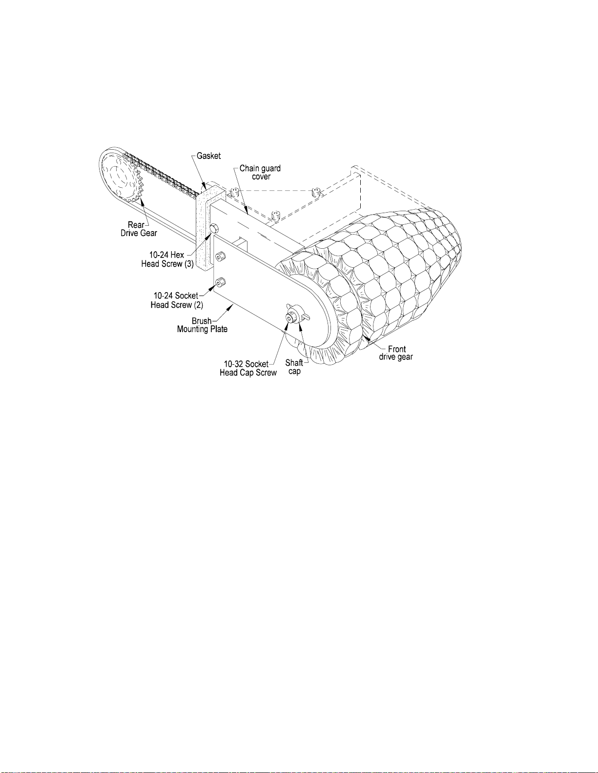
C. CHAIN REPLACEMENT PROCEDURE:
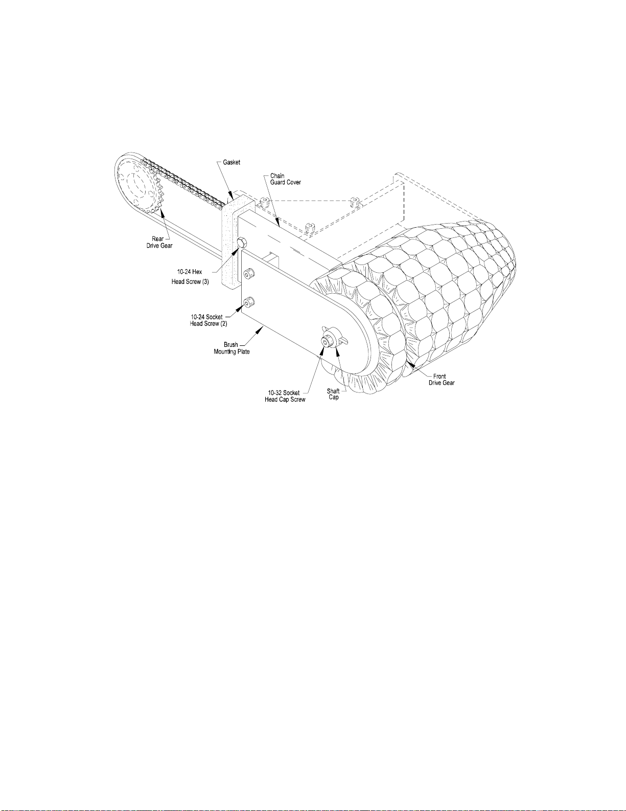
Figure 3.2
The drive chains, are preassembled at the chain
factory, and have no Master Links. The chain is
also lubricated at the factory. (stainless steel drive
chain excluded). The chains can be replaced with
out breaking the chain apart.
1. Disconnect power to the bag tensioner.
2. Remove the main gear cover.
3. Remove the two 10-32 socket head screws
connecting the shaft cap to the ends of the
brush shaft. Remove the two 10-24 socket
head screws at the rear of the brush mounting
plate and remove the plate from the tensioner.
4. Remove the three 10-24 hex head screws,
which fasten the chain guard cover to the
chain guard mounting block. Remove the
cover from the tensioner.
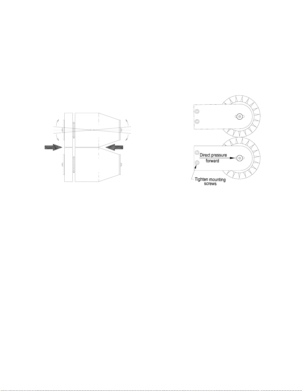
5. Turn the brush assembly by hand and work the
chain off the drive gear at the rear of the
tensioner.
6. Remove the chain from the tensioner.
7. Install the new chain around the brush
assembly sprocket. Work the chain through the
gasket and then around the second sprocket.
8. Replace the chain guide cover, the brush
mounting plate and the main gear cover.
9. Refer to part A. number 2 to adjust the tension
of the new chain before operating the tensioner
under power.
D. MOTOR RESET:
Thermal overload protection is built into the bag ten-
sioner motor. Should the thermal overload trip, reset the
motor as follows:
1. Allow the motor to cool. Remove power from
the bag tensioner to reset the thermal overload.
Apply power to the bag tensioner to restart the
motor.
Figure 3.2
J8S 06 04

P 4.1
SECTION IV
Adjustments
A. ADJUST BRUSH TRACKING.
Figure 4.1 and 4.2
The bagneck should be as flat and wrinkle free as
possible as it enters the closer. The two brush assem-
blies should be parallel where they contact to optimize
the tensioners ability to prepare the bagneck for entry
into the closer. (Figure 4.1) The brush mount plates
mount with two 10-24 x 1/2" socket head cap screws.
These screws are used to align the brushes as follows.
1. Loosen the two plate mounting screws on the
side of the brush assembly to be aligned.
2. Hold the brush mount plate in your hand.
3. Apply pressure to the back of the plate (opposite
the curved end) in a forward direction toward the
brush assembly (Figure 4.2).
4. Raise or lower until the brush mount plate is
pressed firmly against both mounting screws.
(The mounting holes are oversized allowing for
this adjustment) Tighten the mounting screws.
5. From the front of the tensioner check the gap
between the two brush assemblies and verify
that they are now parallel (this does not apply
to the tapered portion of brush assembly).
6. If needed, repeat the adjustment.
CAUTION: DISCONNECT POWER TO THE
BAG TENSIONER BEFORE CONDUCTIONG
ADJUSTMENTS.
J8S 06 04
Figure 4.1 Figure 4.2

P 4.2
SECTION IV
Adjustments
B. ADJUST THE BRUSH DRIVE CHAIN(S)
Figure 4.
1. Loosen the 10-32 socket head screws on
either end of the shaft cap.
2. Loosen the socket head screws at the discharge
end of the brush shaft.
3. Place fingers on the brush assembly as detailed
in figure 3.1.
4. Apply enough pressure to take up slack in the
drive chain.
5. Tighten the mounting screw.
6. Check the location of the of the screw in the slot
and compare it to the other mounting screw in
the other side of the brush shaft. Adjust if
needed to keep the brushes aligned.
Figure 4.3
J8S 06 04

P 5.1
SECTION V
Parts Identification
WARNING: DO NOT ORDER PARTS BY ITEM NUMBER.
Be sure to order by Part Number and Description. Please
list the Serial Number of the machine for which the parts
are being ordered.
PARTS ORDERING PROCEDURES
IMPORTANT: The 1082J8S Stainless Bag Tensioner is available in right and left hand models. ALL ILLUSTRA-
TIONS DEPICTED IN THIS MANUAL ARE CONFIGURED TO A RIGHT HAND MODEL BAG TENSIONER. Parts
lists include part numbers for both right and left hand models when applicable. Determine the hand of the machine
so as to insure that the correct parts are ordered. Information is contained in the front parts section of the closer
manual to establish if your machine is either right or left hand.
When ordering parts ALWAYS:
1. Specify on the order the TYPE, MODEL, and SERIAL NUMBER of the machine for which parts are being
ordered. This information will be found on the machine’s nameplate, and;
2. Do NOT order by item number. Order by PART, or KIT NUMBER.
There is an option for ordering individual replacement PARTS, or for ordering replacement “KITS”. A KIT is an
option for related PARTS combined under one number. These KITS provide three functions:
1. To combine various PARTS that make up a machine model.
2. To provide options to the basic machine (e.g. UPPER FENCE).
3. To facilitate ordering and stocking of spare parts (e.g. apare parts page in the Appendix).
To order individual PARTS, be sure to observe the following procedure:
A. Identify the desired PART(S) by referring to the assembly illustrations (pages 5.2 - 5.11). Each PART is
assigned an “Item Number” on the illustration. DO NOT ORDER BY ITEM NUMBER.
B. Refer to the parts list. Locate the pertinent item number in the left-hand column. Opposite the item
number is the part number and description to be listed in the order.
C. Specify on the order the TYPE, MODEL, and SERIAL NUMBER of the machine for which parts are being
ordered. This information will be found on the machine nameplate.
As an example - on Page 5.3, item 1 is the KNOB - UPPER BRUSH MOUNT ADJUST. When ordering the
replacement part(s) use the PART NUMBER AND DESCRIPTION. Using the machine description located on
the nameplate, the order should specify;
“One Part Number 08-000566, KNOB - UPPER BRUSH MOUNT ADJUST
for the Bag Tensioner Type 1082J8S Model MR, Serial Number 1001"
J8S 06 04

P 5.2
SECTION V
Parts Identification WARNING: DO NOT ORDER PARTS BY ITEM NUMBER.
Be sure to order by Part Number and Description. Please
list the Serial Number of the machine for which the parts
are being ordered.
1/8 HP MEDIUM DUTY FRAME
Figure 5.1
J8S 06 06

P 5.3
SECTION V
Parts Identification
WARNING: DO NOT ORDER PARTS BY ITEM NUMBER.
Be sure to order by Part Number and Description. Please
list the Serial Number of the machine for which the parts
are being ordered.
1 08-000566 Knob - Upper Brush Mount
Adjust 1
2 08-001844S Bracket - Knuckle Mount 1
3 08-002031 Plug - Nylon 1
4 08-002966-SRFence - Upper Cone- Model M
(right-hand machine) 1
08-002966-SL Fence - Upper Cone - Model M
(left-hand machine) 1
5 08-002967-SRClamp - Fence Support
Model M (right-hand machine) 1
08-002967-SL Clamp - Fence Support
Model M (left-hand machine) 1
6 08-002968-SRBracket - Upper Fence Mount
Model M (right-hand machine) 1
08-002968-SL Bracket - Upper Fence Mount
Model M (left-hand machine) 1
7 08-003446-SRCover - Gear
(right-hand machine) 1
08-003446-SL Cover - Gear
(left-hand machine) 1
8 08-002423S Bearing - Adjust Rod 1
9 08-002424S Knuckle 1
10 08-004886-SRFrame (right-hand machine) 1
08-004886-SL Frame (left-hand machine) 1
11 08-002445 Rod - Brush Adjust (1/8 HP) 1
12 0W-002S Washer 2
13 P11-00243 Cord - Electrical 72"
P11-00736 Cord - Electrical - International 72”
14 P11-00159 Plug - Electrical - 200 - 250VAC
Watertite 1
15 P11-00162 Plug - 115VAC - Watertite 1
16 P21-00072A Motor - 1/8 HP
115VAC - 50/60 Hz 1
P21-00207 Motor - 1/8 HP
200/250 VAC - 50/60 Hz 1
17 P11-00109 Terminal - Closed Loop 1
18 P11-00260 Nut - Wire 4
19 P11-00407 Strain Relief 1
20 P21-00208 Capacitor - 200VAC - 50-60 Hz 1
P21-00209 Capacitor - 220VAC-250VAC
50-60 Hz 1
21 P23-00108S Pin 3/16 x 1/2 Lg 1
22 P27-00054S Ring - Retaining 1
23 F14-252S Washer - 3/16 Flat 1
24 F01-250S Washer - 1/4 Flat 2
25 F02-190S Washer - No. 10 Sp Lk 4
26 F02-250S Washer - 1/4 Sp Lk 5
27 F06-190C03SNScrew - 10-24UNC x 3/16" Lg
Nylok Skt Set 1
28 F06-250C04S Screw - 1/4UNC x 1/4" Lg
Skt Set 1
29 F10-190C08S Screw - 10-24UNC x 1/2" Lg
Skt Hd Cap 2
30 F11-190F05S Screw - 10-32UNF x 5/16" Lg
Skt Btn Hd 5
31 F11-190C08S Screw - 10-24UNC x 1/2" Lg
Skt Btn Hd 2
32 F12-250C08S Screw - 1/4-20UNC x 1/2" Lg
Skt Flt Hd 4
33 F13-250F08S Screw - 1/4-28UNF x 1/2" Lg
Hx Hd 3
34 F13-250F10S Screw - 1/4-28UNF x 5/8" Lg
Hex Hd 2
35 P11-00160 Recepticle - HV - Watertite 1
36 P11-00163 Recepticle - LV - Watertite 1
1/8 HP MEDIUM DUTY FRAME
(Figure 5.1)
Item Part
No. No. Description Qty. Item Part
No. No. Description Qty.
PARTS LIST
J8S 06 06

P 5.4
SECTION V
Parts Identification WARNING: DO NOT ORDER PARTS BY ITEM NUMBER.
Be sure to order by Part Number and Description. Please
list the Serial Number of the machine for which the parts
are being ordered.
SHORT BRUSH ARM ASSEMBLY
(TWO ASSEMBLIES PER MACHINE)
J8S 06 04
Figure 5.2

P 5.5
SECTION V
Parts Identification
WARNING: DO NOT ORDER PARTS BY ITEM NUMBER.
Be sure to order by Part Number and Description. Please
list the Serial Number of the machine for which the parts
are being ordered.
1 08-002425 Pivot - Brush Mount 1
2 08-002426 Gusset - Brush Mount 2
3 08-002432 Gasket - Chain Guard 2
4 08-002435 Plate - Brush Mount 1
5 08-002436 Bar - Brush Mount - Short 1
6 08-002439 Plate - Brush Mount 1
7 08-002452 Shelf - Bagneck
(one per machine) 1
8 08-002460 Chain - Brush Drive 1
9 08-002461-R Cover - Chain Guard
(right-hand) 1
08-002461-L Cover - Chain Guard
(left-hand shown) 1
10 08-002462 Guard - Chain 1
11 08-004877 Shim - Wear 2
12 08-004878 Mount - Chain Guard 1
13 08-005558 Cap - Shaft 2
14 P23-00068S Nut - 1/4-28UNF ESNA 2
15 F01-190S Washer - No. 10 Flat 3
16 F10-138C08S Screw - 6-32UNC x 1/2" Lg
Skt Hd Cap 4
17 F10-190C08S Screw - 10-24UNC x 1/2" Lg
Skt Hd Cap 10
18 F10-190C12S Screw - 10-24UNC x 3/4" Lg
Skt Hd Cap 4
19 F10-190F10S Screw - 10-32UNF x 5/8" Lg
Skt Hd Cap 2
20 F12-250F16S Screw - 1/4-28UNF x 1" Lg
Skt Flt Hd 1
21 F13-190C04S Screw - 10-24UNC x 1/4" Lg
Hx Hd 6
22 F13-250F16S Screw - 1/4-28UNF x 1" Lg
Hx Hd 1
23 F14-252S Washer - 3/16 USS Flt 3
SHORT BRUSH ARM ASSEMBLY
(TWO ASSEMBLIES PER MACHINE)
Figure 5.2
Item Part
No. No. Description Qty. Item Part
No. No. Description Qty.
PARTS LIST
J8S 06 04

P 5.6
SECTION V
Parts Identification WARNING: DO NOT ORDER PARTS BY ITEM NUMBER.
Be sure to order by Part Number and Description. Please
list the Serial Number of the machine for which the parts
are being ordered.
LONG BRUSH ARM ASSEMBLY
(TWO ASSEMBLIES PER MACHINE)
J8S 06 04
Figure 5.3

P 5.7
SECTION V
Parts Identification
WARNING: DO NOT ORDER PARTS BY ITEM NUMBER.
Be sure to order by Part Number and Description. Please
list the Serial Number of the machine for which the parts
are being ordered.
1 08-002425 Pivot - Brush Mount 1
2 08-002426 Gusset - Brush Mount 2
3 08-002432 Gasket - Chain Guard 2
4 08-002439 Plate - Brush Mount 2
5 08-002440 Bar - Brush Mount -Long 1
6 08-002452 Shelf - Bagneck
(one per machine) 1
7 08-002460 Chain - Brush Drive 1
8 08-002461-R Cover - Chain Guard
Right Hand 1
08-002461-L Cover - Chain Guard
Left Hand (shown) 1
9 08-002462 Guard - Chain 1
10 08-004877 Shim - Wear 2
11 08-004878 Mount - Chain Guard 1
12 08-005558 Cap - Shaft 2
13 P23-00068 Nut - 1/4-28UNF ESNA 2
14 F01-190S Washer - No. 10 Flat 3
15 F10-138C08S Screw - 6-32UNC x 1/2" Lg
Skt Hd Cap 4
16 F10-190C08S Screw - 10-24UNC x 1/2" Lg
Skt Hd Cap 10
17 F10-190C12S Screw - 10-24UNC x 3/4" Lg
Skt Hd Cap 4
18 F10-190F10S Screw - 10-32UNF x 5/8" Lg
Skt Hd Cap 2
19 F12-250F16S Screw - 1/4-28UNF x 1" Lg
Skt Flt Hd 1
20 F13-190C04S Screw - 10-24UNC x 1/4" Lg
Hx Hd 6
21 F13-250F16S Screw - 1/4-28UNF x 1" Lg
Hx Hd 1
22 F14-252S Washer - 3/16 USS Flt 3
LONG BRUSH ARM ASSEMBLY
(TWO ASSEMBLIES PER MACHINE)
Figure 5.3
Item Part
No. No. Description Qty. Item Part
No. No. Description Qty.
PARTS LIST
J8S 06 04

P 5.8
SECTION V
Parts Identification WARNING: DO NOT ORDER PARTS BY ITEM NUMBER.
Be sure to order by Part Number and Description. Please
list the Serial Number of the machine for which the parts
are being ordered.
1 08-002433 Brush - End 1
2 08-002434 Brush - Short Soft Cone 1
3 08-002459 Sprocket - Drive Chain 1
4 08-004884 Shaft - Short Brush 1
5 0S-062 Spring - Compression 1
6 P02-00113 Bearing 2
7 P27-00018S Ring - Retaining 2
8 F10-190C32S Screw - 10-24UNC x 2" Lg
Skt Hd Cap 4
BRUSH ASSEMBLY - SHORT SOFT CONE
(TWO ASSEMBLIES PER MACHINE)
Item Part
No. No. Description Qty.
PARTS LIST
J8S 06 04
Figure 5.4

P 5.9
SECTION V
Parts Identification
WARNING: DO NOT ORDER PARTS BY ITEM NUMBER.
Be sure to order by Part Number and Description. Please
list the Serial Number of the machine for which the parts
are being ordered.
1 08-002433 Brush - End 1
2 08-002438 Brush - Long - Stiff - Straight 1
3 08-002459 Sprocket - Drive Chain 1
4 08-004889 Shaft - Brush - Long 1
5 0S-062 Spring - Compression 1
6 P02-00113 Bearing 2
7 P27-00018S Ring - Retaining 2
8 F10-190C32S Screw - 10-24UNC x 2" Lg
Skt Hd Cap 4
LONG BRUSH ASSEMBLY
(TWO ASSEMBLIES PER MACHINE)
Item Part
No. No. Description Qty.
PARTS LIST
J8S 06 04
Figure 5.5

P 5.10
SECTION V
Parts Identification WARNING: DO NOT ORDER PARTS BY ITEM NUMBER.
Be sure to order by Part Number and Description. Please
list the Serial Number of the machine for which the parts
are being ordered.
1 08-002416 Gear - Motor 1
2 08-002418 Gear 1
3 08-002419 Gear 1
4 08-002422 Bushing - Bearing 2
5 08-002459 Sprocket - Chain 2
6 08-004883 Shaft - Gear 2
7 0S-062 Spring - Compression - Gear 2
8 P02-00113 Bearing 4
9 P27-00053S Ring - Retaining 2
10 F14-252S Washer - 3/16 USS Flt 2
Item Part
No. No. Description Qty. Item Part
No. No. Description Qty.
PARTS LIST
J8S 06 04
Figure 5.6
1/8 HP GEARS - MEDIUM DUTY FRAME
11 F02-250S Washer - 1/4 Sp Lk 2
12 F06-250C05S Screw - 1/4-20UNC x 5/16" Lg
Skt Set 2
13 F10-190C12S Screw - 10-24UNC x 3/4" Lg
Skt Hd Cap 8
14 F10-250F06S Screw - 1/4-28UNF x 3/8" Lg
Skt Hd Cap 2
15 F13-250F08S Screw - 1/4-28UNF x 1/2" Lg
Hex Hd 2
16 0W-002S Washer 2
Table of contents
Other Kwik Lok Food Saver manuals