Model 3050 Installation Instructions
KWIK-WALL COMPANY Operable Wall Systems
3
Wiring:
All wiring would be by others and a qualified Electrician will need to provide correct power
supply, conduits, and gang boxes per wire diagram of wall.
A separate disconnect is required for operator, optional automatic closure, and optional
guardian systems as required. Please see print as noted.
Optional Guardian unit, lead edge, mats will be shipped from Kwik-Wall with panels.
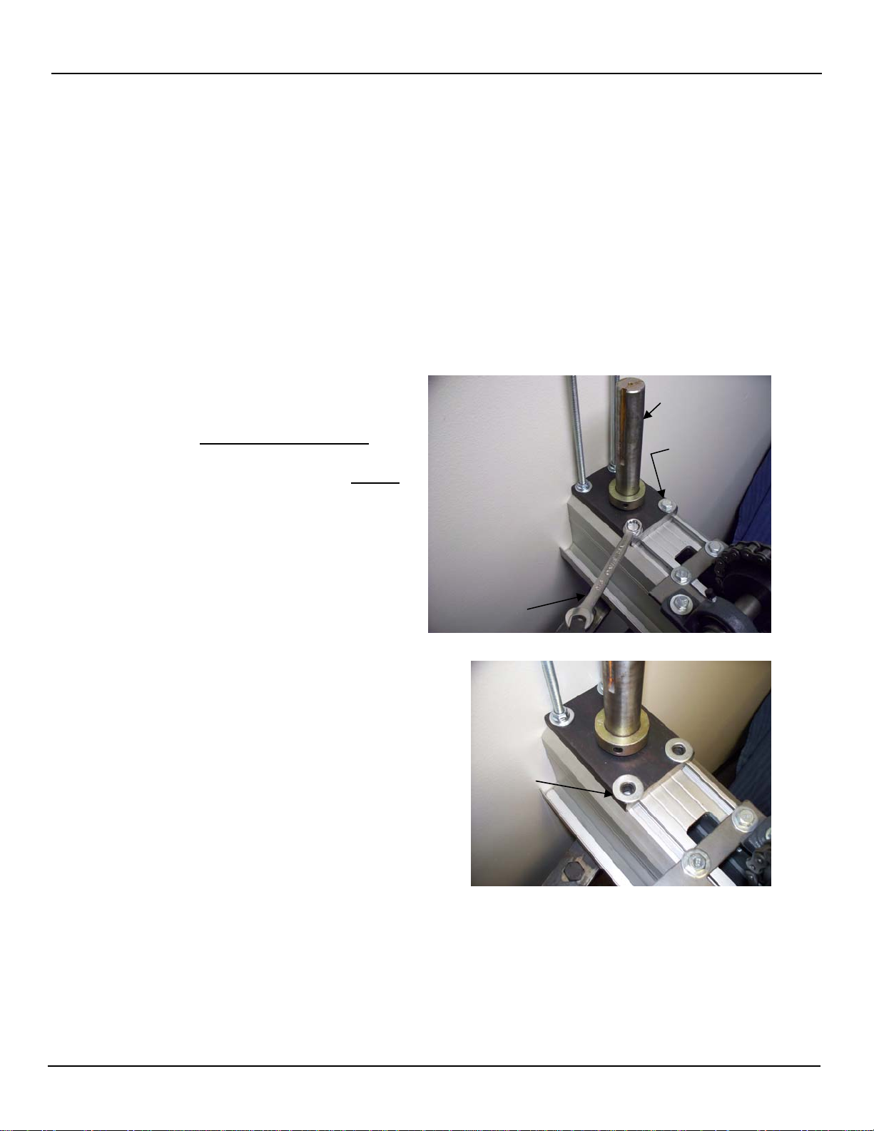
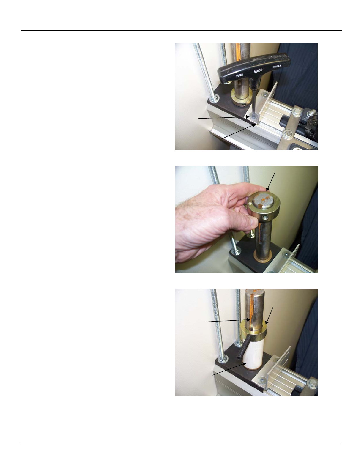
Install ½ panel:
Use laser to mark X location for bearing plate. Oblong slots and set screws are for left or right
side plumb adjustment. Install wiper sweep per orientation of print. Position bearing plate
directly under center pivot arm and bolt to floor. Lift ½ panel into place with pivot arm bolt
sliding into top of panel, bottom pivot adjustment shaft will set into bearing. Adjust
threaded shaft raising bottom of panel to 2” above finished floor. Lock adjustments and
replace ½ round cap. Swing pivot to insure that it moves freely.
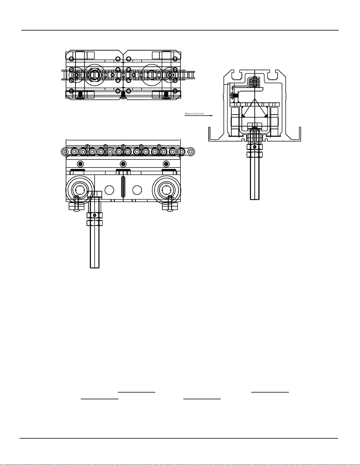
Install panels:
Lower escapement drop out. Load panels one at a time into track in reverse order. Note lead
trolley orientation with extra length point away from stack.
All floating trolley panels must be oriented with the slot of floating trolley is facing towards the
lead edge of the panel. Reversing this orientation will cause the wall to bind.
(If lead panel has an automatic floor seal then mark screw locations bottom seal and remove
automatic bottom seal prior to placing panel in the track.) Replace escapement section of
track.
Pin adjacent panels together, one at a time, starting with ½ panel in stack. With panel flat in
stack remove trolley wire. See page 12 for the wire hook removal. Check for smooth
operation, sliding trolley forward, roll and adjust trolley height. Repeat for all panels.
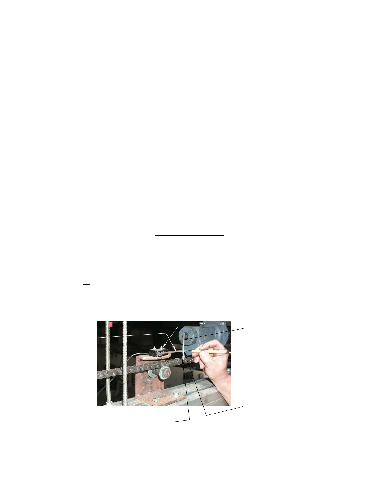
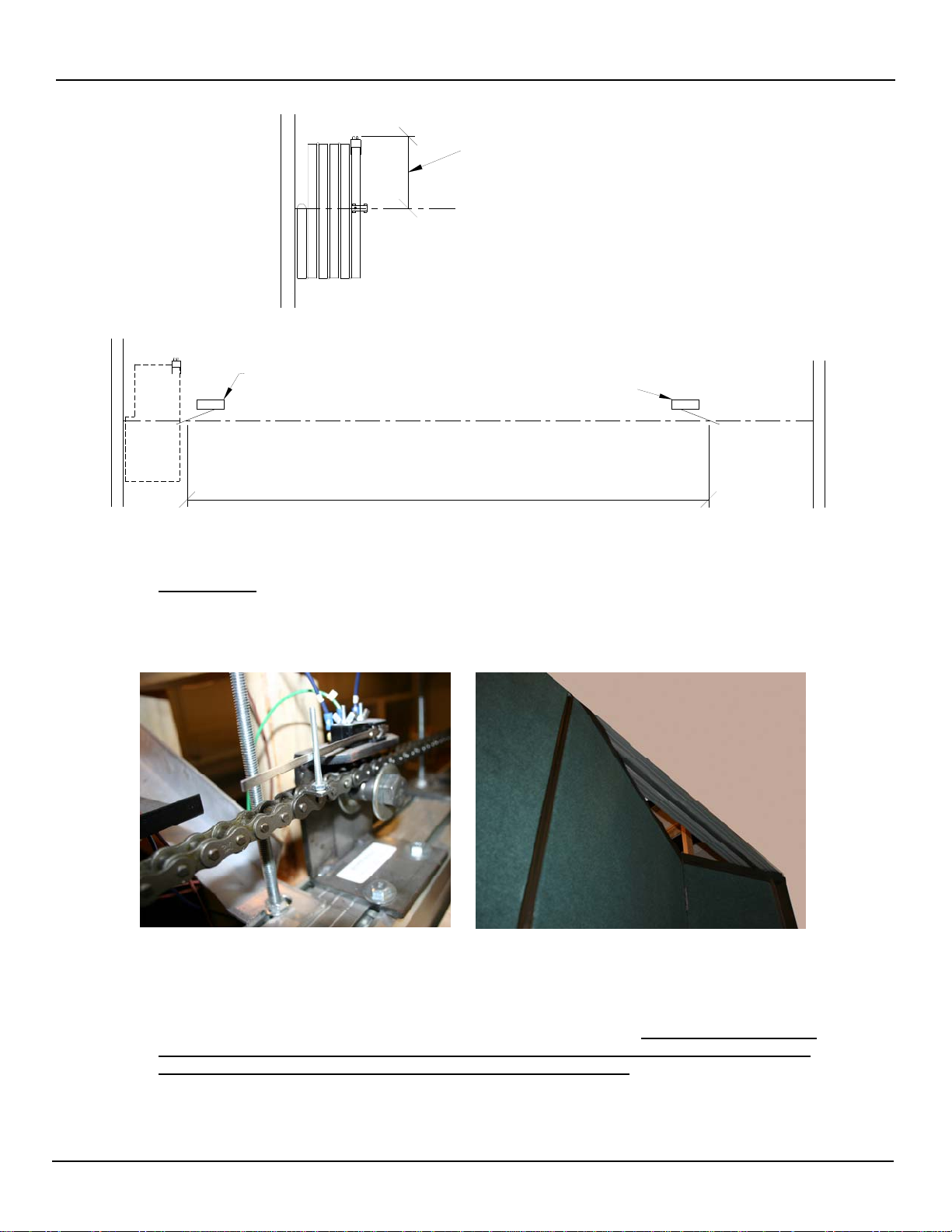
Attaching chain to lead trolley:
See page 5 “Model 3050 Installation Instructions for Extend & Retract limit switch Positions.
This also covers chain location and lead trolley attachment.