Electric Steps #888 Page 8
Troubleshooting and Testing Procedures, Cont
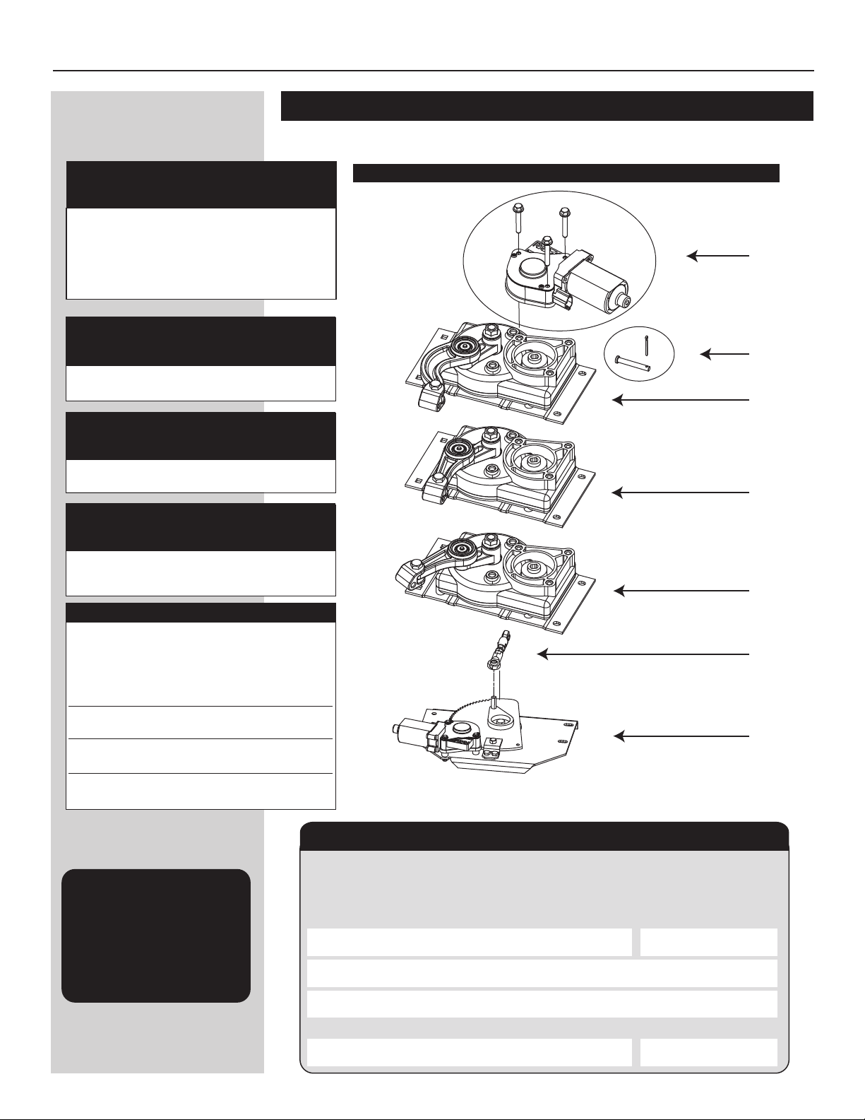
TESTING THE STEP
1. Inspect the step for visible damage that might restrict step operation
2. Obtain a 4-way pigtail connector (part #909306000) from Kwikee
3. Diconnect 4-way connector on underside of step and connect the step-half of the
connector to the four-way connector pigtail. See Figures 10, 11, and 12 on
Page 9
4. Set a fully charged 12V DC automotive battery beside the step.
NOTE: Do not allow the battery terminals to come in contact
with the step.
Complete a ground for the step tests by connecting a 10 gauge wire from the
negative (-) battery post to the green ground wire of the control unit
5. To supply power, attach the red wire from the pigtail to the battery’s positive (+)
post. The step will extend
6. With the power and ground connections complete, all functions of the control unit
can be checked at the four wires of the pigtail. The brown wire is the door
switch, the white wire is the step lockout switch, and the yellow wire is the
ignition override
7. To retract the step, touch the brown wire to the negative (-) terminal
8. To extend the step, remove the brown wire from the negative (-) terminal
9. To test the ignition override feature, extend the step as in Step 8. With the step
extended, connect the white wire to the positive (+) terminal and attach the
brown wire to the negative (-) terminal. Next, touch the yellow wire to the
battery’s positive (+) terminal. The step should retract. Remove the brown wire
and the step should extend
10.If any of the step functions do not work, the source of the malfunction is either in
the control unit and/or the motor. Proceed to the “Testing the Motor” section on
Page 10.
If all of the step functions do work, the malfunction is either in the door switch, step
lockout switch, or the vehicle wiring. Proceed to “Testing the 4-way Connector”
section on Page 10.
To test the “Auto Extend” feature, touch the brown wire to the negative (-) terminal to
retract the step. While holding the brown wire to the negative (-) terminal, remove
the yellow from the positive (+) terminal. Touch the white wire to the positive (+)
terminal. The step will stay retracted.
Now, remove the brown wire and the step should extend
Next touch the brown wire to the negative (-) terminal. The step should stay
extended.
IMPORTANT INSTALLER NOTES:
Be sure that all ground
connections are securely
fastened with good
metal-to-metal contact. A
good ground is required for
proper step operation
VAN STEPS
If the van step is equipped with a splash cover, remove the cover to access motor
assembly and control unit. If step is locked in retracted (up) position and the plastic
cover can not be removed, disassemble the step tread to access the plastic cover
To disassemble the tread, remove the (8) 1/4-20 x 1” long hex head bolts in tread
side rails (connects tread and sliding blocks to side rail). This allows the tread to
drop out of the way and the plastic cover to be accessible
Reassemble the tread after removing the cover. Reinstall the cover after testing
procedures and any necessary repairs are complete. Fully extend the step to
reinstall the cover. Be sure that the four-way connector exits the notch in the plastic
cover when reassembling
WARNING
!
12 volt automotive batteries
contain sulfuric acid which
can cause severe burns.
Avoid contact with the skin,
eyes, and clothing. 12 volt
automotive batteries produce
hydrogen gas which is explo-
sive; keep cigarettes, open
flames, and sparks away from
the battery at all times
WARNING
!
Keep fingers, arms, and legs
clear of step mechanism while
performing these test. Failure
to do so may result in
personal injury
CAUTION
!
Do not allow the battery
terminals to come in
contact with the step.