Kwikee 90615 Series User manual

90615 Series
Step Well Covers
Step Well Cover
Operating Instructions
Overview
The 90615 Series Step Well Covers,
manufactured by Kwikee Products
Company, Inc., are designed for
front-entry coaches. The step well
cover provides comfort and foot-
support for the person riding in the
passenger seat. The step well cover
also provides added user safety by
preventing accidental falls into the
entry step well.
The construction of the step well
cover consists of three primary parts:
1) Outer shell
2) Slider
3) Drive mechanism
The outer shell connects directly to
the chassis of the motor coach and
provides the structural support and
environmental protection for the drive
mechanism and slider.
The slider is the portion of the slide
that extends and that the user sees
during normal operation.
The drive mechanism is responsible
for providing the power to drive the
slider in and out and also provides
the Emergency Retract function.
5/03 Kwikee Products Co., Inc.
Kwikee #1422194 Rev. 2 5/03
Extension
To extend the unit, first make sure that
there are no obstructions in the step well
which will interfere with the operation of the
unit. Locate the step well slide rocker
switch and position yourself fully inside the
coach. Do not stand in the entry step well.
Press and hold the rocker switch in the
extend position until the unit is fully
extended and stops moving.
Verify that the slide is fully extended by
visually checking to see that the unit is
level and parallel to the main floor and that
the front edge of the slide is resting on the
support blocks next to the entry door.
Retraction
To retract the unit, first make sure that
there is nothing laying on top of the slider.
Locate the step well slide rocker switch
and position yourself fully inside the coach.
Press and hold the rocker switch in the
retract position until the unit is fully
retracted and stops movement.
Verify that the slide is fully retracted by
visually checking to see that the unit is
flush with the back part of the step.
Emergency Retract Feature
CAUTION Do not active
Emergency Retract unless
necessary. Operation of the Emergency
Retract will cause the unit to become
non-functional until the cable system
has been reconnected.
In the event of a failure in the slide unit in
the extended position, the floor slide is
equipped with an Emergency Retract
Figure 1A
Figure 1B
Figure 1C
Figure 1D
DO NOT RIDE THE SLIDER DURING OPERATION.
function. The emergency cable release is
located at the front of the slide under a
black plastic snap-
in cover labeled
Emergency Retract
(Figure 1A). To
release the slide in
an emergency
requiring exiting the
coach, remove the
black plastic cover
by pulling it up and
to the side (Figure
1B).
Depending on the model of the step well
cover, in the opening you will see either a
gold colored lever or a bead-chain.
If it is the gold
colored lever
(Figure 1C).
Push sharply
down on the
lever and the
cable will
release,
allowing you to
manually push
the slide in.
The bead-chain is
attached to the
black plastic
cover and as you
remove it, the
chain will pull the
release allowing
you to manually
push the slide in
(Figure 1D).

Figure 4A
Figure 4B
Figure 5
90615 Series Step Well Cover Operating Instructions Page 2
Cable Rewind Procedure
In the event that the emergency cable
release is activated, the cable system will
need to be reconnected. The following
procedure should be followed to
reconnect the cable system.
1. Manually extend the floor slide to
approximately ¾ of full travel and
have someone hold it in this position
or lock it in this position using a cut
block of wood or other part that is of
suitable length and will not scratch
the floor slide.
2. Locate the spring assembly that was
released from the cable release latch
(Figure 2).
3. Pull it out toward the front of the unit
and set it aside.
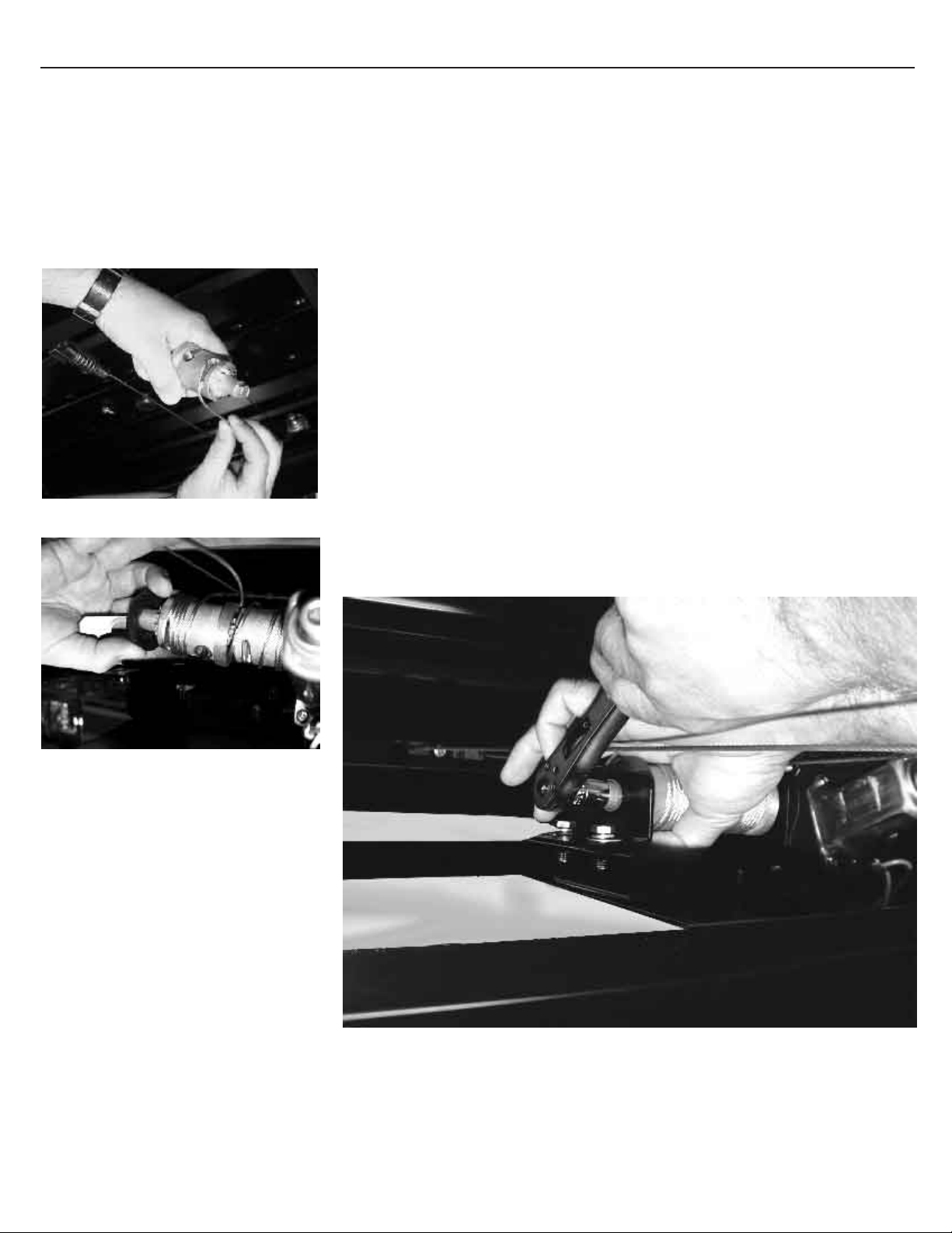
4. Remove the two ¼"-20-hex bolts, flat
washers, and lock washers that hold
the cable drum in place and set them
where they will be easily accessible
for later use (Figure 3).
5. Remove the black plastic end cap
and outer drum assembly and set
aside for later use.
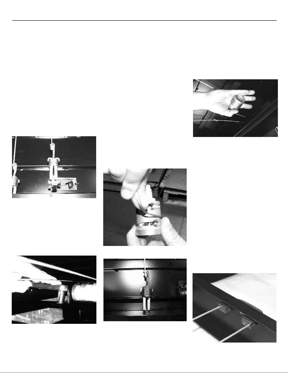
6. Remove the inner drum (closest to
the motor) and unwind the cable that
is attached to it. If the cable is no
longer attached to the drum, insert
the crimped cable end into the slot
located next to the female end of the
drum. Begin winding the cable in a
clockwise direction as viewed from
the male end of the drum. Wind the
cable on the drum so that it is shorter
than what is needed to slip the motor
side over the motor gear. Make sure
not to cross the cable and make even
tight wraps around the drum (Figure
4A).
Make sure that the motor side drum
cable (short cable) is connected to
the motor side spring assembly and
to the front of the slider (Figure 4B).
7. Grasp the drum with the cable
between your fingers and push your
hand toward the motor allowing the
drum to unwind in your hand. Make
sure to keep the cable tight. Unwind
only enough cable to align the drum
with motor gear teeth and slide the
drum over the motor gear teeth fully
(Figure 5).
8. Connect the outer drum spring
assembly to the latch and ensure that
it is locked down and the latch is fully
closed. To accomplish this it will
require compressing the spring
slightly while closing the latch, as
shown in Figure 2.
The cable should be routed from the
spring around the plastic U-Block in
the back of the slide and up past the
motor assembly (Figure 6A). Grasp
the remaining drum and check to
ensure that the cable is inserted into
the slot on the male end of the cable
drum and begin winding the drum in a
counter clockwise direction. As you
run out of cable begin rolling the drum
in towards the drum connected to the
motor taking up the cable and winding
it on the drum as you go.
Figure 2 (Attached spring system)
Figure 3
Figure 6A

90615 Series Step Well Cover Operating Instructions Page 3
Once in line, slide the female end
of the outer drum over the male
end of the drum previously placed
and engage the gear teeth. Place the
plastic drum end cap over the outer
most drum and replace the drum
L-bracket with the flat washer,
lock washer, and bolt (Figures 6B,
and 6C).
Tighten the L-bracket bolts only
enough to take up the slop; the
bracket should be able to slide in and
out by hand with a little effort, as
shown in Figure 3.
NOTE: Make sure that the cable is not
crossed over or pinched between the
two drums.
9. Connect a ratchet to the end of the
outer most drum using a 7/16" socket.
With one hand, hold the drum closest
to the motor in place and with the
other hand slide the outer drum away
from the inner drum slightly to
disengage the mating teeth. Now
release the drum closest to the motor
and it will stay there.
Hold the outer most drum and begin
tightening the cable by rotating the
outer most drum in a clockwise
direction using the ratchet attached to
the end of the drum. Tighten the
cable until all of the slack is out of
both the springs at the front of the
slide unit and then wiggle the drum
back and forth while pushing it in with
the ratchet to engage the closest pair
of teeth between the two drums.
Make sure both drums are fully
engaged (Figure 7).
10. Slide the L-bracket inward toward the
motor and take up all of the clearance
between the end of the drum and the
plastic end cap.
Make sure that:
■ The drums are fully engaged on
the motor
■ The drums are fully engaged with
each other.
■ The drum end cap is covering the
end of the drum.
Tighten the bolts on the L-bracket,
making sure to keep it square in
relation to the drums and the
mounting surface.
11. Remove the spacer that was holding
the slide in the out position and run
the slide in and out several times to
make sure that it is working properly.
Check for crossed cables and proper
cable tension. The cables should not
be loose and the springs should be
tensioned at all points of the travel.
12. If the springs are loose, loosen the
L-bracket slightly to allow it to move
slightly and repeat Step 9.
Figure 6B
Figure 6C
Figure 7

Kwikee Products Company, Inc.
230 Davidson Avenue
Cottage Grove, Oregon 97424-9545
(541) 942-3888
www.kwikee.com
Other Kwikee Automobile Accessories manuals
Popular Automobile Accessories manuals by other brands

Bestop
Bestop Pavement Ends 56844 installation instructions

Seizmik
Seizmik 08072 Installation & operation manual

Thule
Thule Flow instructions

dirna Bergstrom
dirna Bergstrom bycool SPLIT OFF ROAD User handbook

Nakatanenga
Nakatanenga HL-DEF FITTING INSTRUCTION

Over Armour Offroad
Over Armour Offroad KU-RTVXG850-SDK01 Instructions for Installation and Care