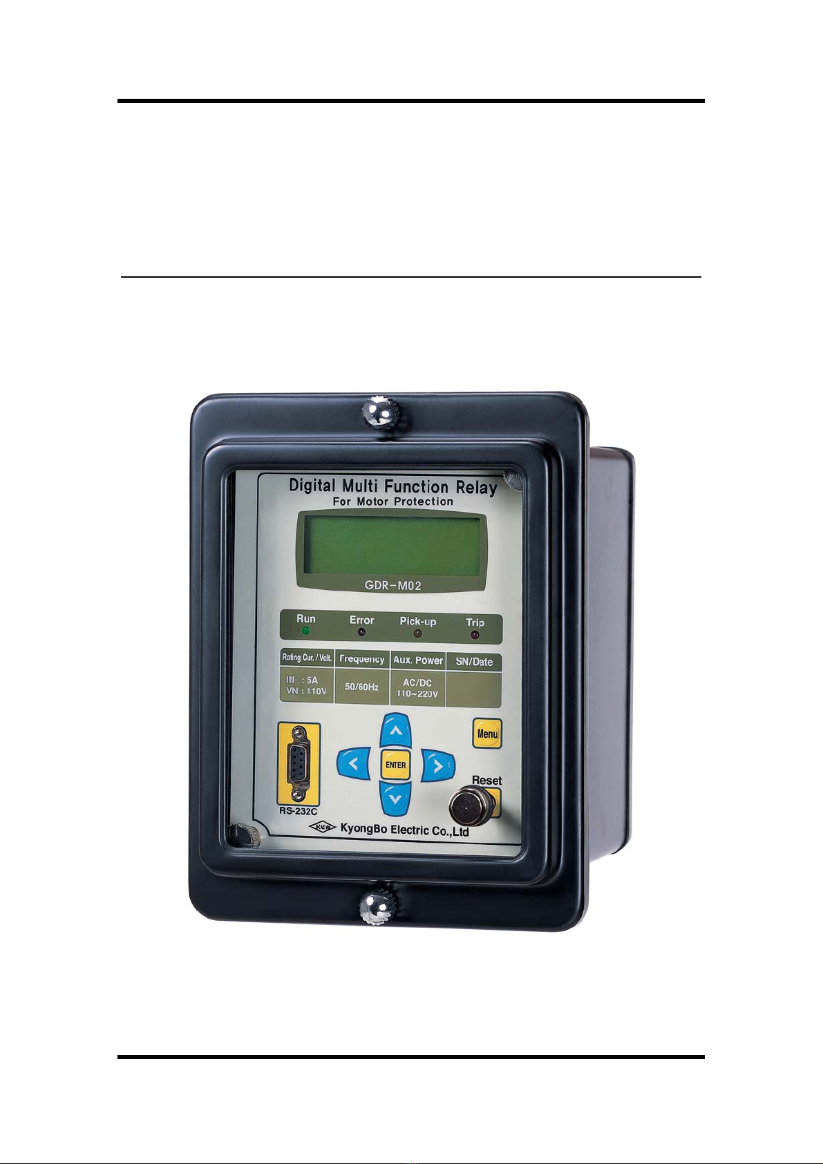
Digital Motor Protection Relay (GDR-M02) User's Manual (V1.00)
7 / 76
KyongBo Electric Co.,Ltd
Order of Table
【Table 2.1】 Input Voltage ································································································· 12
【Table 2.2】 Rated Control Power ···················································································· 12
【Table 2.3】 Case ················································································································ 12
【Table 2.4】 Time OverCurrent Element ·········································································· 13
【Table 2.5】 Instantaneous OverCurrent Element ···························································· 13
【Table 2.6】 Time Ground OverCurrent Element ···························································· 14
【Table 2.7】 Instantaneous Ground OverCurrent Element ·············································· 14
【Table 2.8】 OverVoltage Element ···················································································· 15
【Table 2.9】 UnderVoltage Element ·················································································· 15
【Table 2.10】 Voltage Reverse Phase Element ·································································· 15
【Table 2.11】 Negative-Sequence Current Function ·························································· 16
【Table 2.12】 Output Contacts / Capacity ·········································································· 16
【Table 2.13】 Insulation Test ······························································································· 17
【Table 2.14】 Mechanical Test ···························································································· 18
【Table 2.15】 Noise Test ······································································································ 18
【Table 2.16】 Temperature, Humidity Test ········································································ 19
【Table 2.17】 EMI : ElectroMagnetic Interference ···························································· 19
【Table 2.18】 Other Operating Condition ··········································································· 19
【Table 3.1】 Time Curve Characteristic ············································································ 21
【Table 4.1】 Measurement Function ·················································································· 29
【Table 4.2】 Communication Method ················································································ 30
【Table 5.1】 Key Pad & Communication Connector ······················································ 33
【Table 5.2】 LED ( Operating Indicators ) ······································································ 33
【Table 6.1】 Time OCR Menu ·························································································· 38
【Table 6.2】 INST. OCR Menu ························································································· 39
【Table 6.3】 Time OCGR Menu ······················································································· 39
【Table 6.4】 INST. OCGR Menu ······················································································ 40
【Table 6.5】 OVR Menu ···································································································· 41
【Table 6.6】 UVR Menu ···································································································· 42
【Table 6.7】 NSOCR Menu ······························································································· 42
【Table 6.8】 RPR Menu ····································································································· 43
【Table 6.9】 RS-485 Comm. Setting ················································································· 44
【Table 6.10】 T/S Connection Menus ················································································· 46
【Table 6.11】 Setting Menus ································································································ 51
【Table 7.1】 GDR-M02 Program Menus ·········································································· 54
【Table 7.2】 Communication Port Configuration ····························································· 55