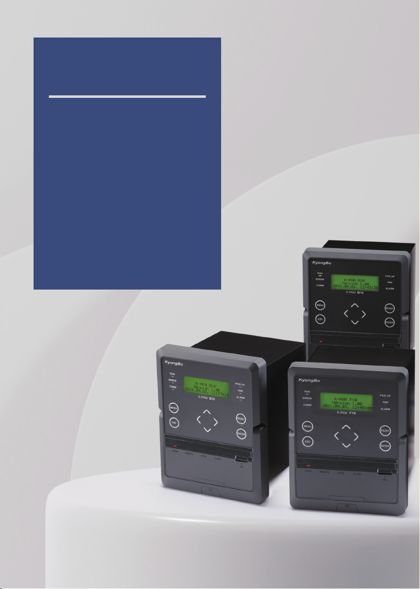
다기능 디지털 복합 보호계전기 K-PAM 5500 Series
9
Kyongbo Electric Co., Ltd.
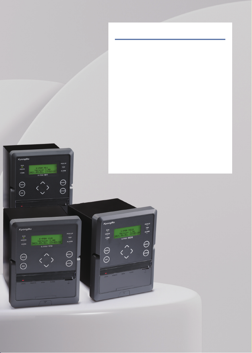
Digital Integrated Protection Relay K-PAM 10 Series
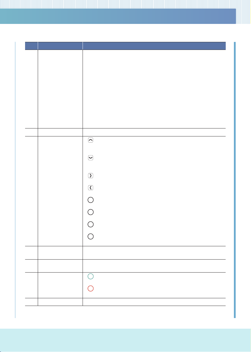
Num Category Description
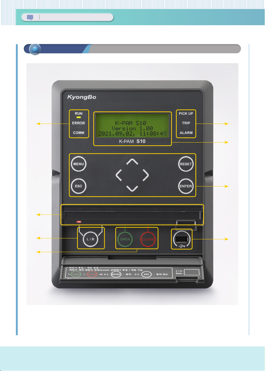
①Status LED
•RUN (GREEN)
- Lights up when the relay is running
•ERROR (RED)
- Lights up when an error occurs as a result of the relay system self-diagnosis
•COMM (YELLOW)
- Blinks when communication with PC is in progress
•PICK UP (YELLOW)
- Lights up when the protection relay element is PICK-UP
•TRIP (RED)
- Lights up when the protection relay element TRIP
•ALARM (YELLOW)
- Lights up when operation after connecting the protection relay element
②4x20 Character LCD •Screen Display
③Button
(UP Key)
- Used to move upwards in a menu category or screen, increase a number
when setting, or change a setting
(Down Key)
- Used to move down on a menu category or screen, decrease a number
when setting, or change a setting
(Right Key)
- Used to move from the menu to the upper menu or to the right when setting
(Left Key)
- Used to move from menu to sub-menu, or to move to the left when setting
MENU Key
- Used to enter the main menu from the screen
ESC Key
- Used to cancel setting when setting is in progress or to cancel test in progress
RESET Key
- Generally used when reset protection elements OP, LED, and D/O
ENTER Key
- Used to save setting changes or to execute control.
④Custom LED •Use of LED desired by the user through setting of relay protection element
operation, etc.
⑤Local/Remote
Contol Button
•L/R Key (LOCAL/REMOTE Key)
- Used when selecting control operation between Local and Remote
⑥CB Close/Open
Control Button
OPEN Key
- Used when CB is OPEN
CLOSE Key
- Used when CB is CLOSE
⑦USB-A Type Port •USB port for connecting relay management software
MENU
ESC
ENTER
OPEN
CLOSE
RESET