manuals.online logo
Brands
  1. Home
  2. •
  3. Brands
  4. •
  5. Kyongbo Electric
  6. •
  7. Relay
  8. •
  9. Kyongbo Electric K-PAM 10 Series User manual

Kyongbo Electric K-PAM 10 Series User manual

K-PAM 10 Series
Digital Integrated Protection Relay
User Manual
Contents
K-PAM 10Series Menu
Front Exterior
Rear Exterior
CB Control Method
Power System Setting Method
Protection relay Element Setting Method
Contact Output Test Method
How to check when a fault occurs
How to check measurement after field installation
Frequently Asked Questions
K-PAM 10Series Control Circuit Diagram
K-PAM 10Series External Wiring
K-PAM 10Series Dimensions
K-PAM 10Series Install/Withdraw Method
04
08
10
12
13
14
20
21
23
24
25
26
29
30
Digital Integrated Protection Relay
K-PAM 10 Series
K-PAM 10 Series is a multi-functional digital Integrated
protection relay that provides high-precision
measurement and reliable protection relay function
for power supply and distribution facilities. Various
protection elements and measuring elements can
be used to protect not only distribution feeders, but
also motors, busses, generators, solar power, ESS, and
wind power generators. In addition, among 6 types
of relays, the user can select a suitable relay for the
need. You can check the fundamental and harmonic
of the system in real time through the measurement
function, and all functions can use USB and RS-485
communication to change settings, change control,
check status and measurement.
다기능 디지털 복합 보호계전기 K-PAM 5500 Series
4 5
Kyongbo Electric Co., Ltd.
Digital Integrated Protection Relay K-PAM 10 Series
MEASUREMENT
RECORDS
STATUS
DEVICE CONFIG
SYSTEM INFO
MENU
VOLTAGE
OCR1
DOCGR
UVR3
PROT STATUS
FREQUENCY
EVENT LIST
POWER
OCR3
OVR1
OVGR2
D/I STATUS
CT RATIO
EVENT CLEAR
FREQUENCY
OCGR2
OVR3
DPR2
R/I STATUS
CIRCUIT BREAKER
CURRENT
OCR2
SGR
OVGR1
CB STATUS
VT RATIO
FAULT LIST
ENERGY
OCGR1
OVR2
DPR1
D/O STATUS
ZCT RATIO
FAULT CLEAR
ENERGY CLEAR
OCGR3
UVR2
UVR1
UPR1
UPR2
CB/DO COUNT
POWER SYSTEM
RELAY SETTING
RELAY SETTING
MEASUREMENT
RECORDS
STATUS
POWER SYSTEM
DEVICE CONFIG
SYSTEM INFO
MENU OVR1
OVGR1
UFR2
PROT STATUS
FREQUENCY
OVR3
NSOVR
D/I STATUS
EVT RATIO
FAULT LIST
UVR2
OFR1
R/I STATUS
REV CON DETECTOR VOLTAGE DETECTOR
FAULT CLEAR
FREQUENCY
OVR2
OVGR2
ROCOF
CB STATUS
VT RATIO
EVENT LIST
UVR1
POR
D/O STATUS
PHASE ROTATION
EVENT CLEAR
VOLTAGE
UVR3
UFR1
OFR2
CB/DO COUNT
CIRCUIT BREAKER
RELAY SETTING
MENU
VOLTAGE
PROT STATUS
FREQUENCY
OCR1
DOCGR2
OVGR2
REMOTE INPUT #7
EVENT LIST
POWER
D/I STATUS
CT RATIO
OCR3
OVR2
REMOTE INPUT #1
DPR2
REMOTE INPUT #9
LED #1
DIGITAL OUTPUT #2
LEDS
EVENT CLEAR
FREQUENCY
R/I STATUS
NCT RATIO
OCGR2
UVR1
REMOTE INPUT #3
UPR2
REMOTE INPUT #11
LED #3
DIGITAL OUTPUT #4
RS-485
REV CON DETECTOR
DOCR2
UVR3
REMOTE INPUT #5
OFR2
REMOTE INPUT #13
LED #5
UFR2
REMOTE INPUT #15
LED #7
D/O TEST
DIGITAL INPUT #2
VOLTAGE DETECTOR
WAVE RECORDS
SYSTEM STATUS
TEST
DIGITAL INPUTS
CURRENT
CB STATUS
VT RATIO
OCR2
OVR1
DPR1
REMOTE INPUT #8
ALARM
DIGITAL OUTPUT #1
REMOTE INPUTS
FAULT LIST
ENERGY
D/O STATUS
EVT RATIO
OCGR1
OVR3
REMOTE INPUT #2
UPR1
REMOTE INPUT #10
LED #2
DIGITAL OUTPUT #3
TIME SET
FAULT CLEAR
ENERGY CLEAR
CB/DO COUNT
PHASE ROTATION
DOCR1
UVR2
REMOTE INPUT #4
OFR1
REMOTE INPUT #12
LED #4
DIGITAL OUTPUT #5
DEVICE ID
TIME
FAULT RESET
CIRCUIT BREAKER
DOCGR1
OVGR1
REMOTE INPUT #6
UFR1
REMOTE INPUT #14
LED #6
D/I TEST
DIGITAL INPUT #1
ROCOF
REMOTE INPUT #16
LED #8
PANEL TEST
DIGITAL INPUT #3
CURRENT DETECTOR
PASSWORD
VERSION
INIT DISPLAY
DIGITAL OUTPUTS
MEASUREMENT
RECORDS
STATUS
POWER SYSTEM
DEVICE CONFIG
SYSTEM INFO
K-PAM 10Series Menu Configuration
※ DEVICE CONFIG and SYSTEM INFO are common to 10 Series.
■ DG10
■ S10
■ V10
다기능 디지털 복합 보호계전기 K-PAM 5500 Series
6 7
Kyongbo Electric Co., Ltd.
Digital Integrated Protection Relay K-PAM 10 Series
RELAY SETTING
MEASUREMENT
RECORDS
STATUS
POWER SYSTEM
DEVICE CONFIG
SYSTEM INFO
MENU OCR1
UVR2
THERMAL
LOCK ROTOR
OCR3
OVGR2
OVR2
NSOVR
OCR2
OVGR1
STALL
NOTCHING
OVR1
SGR
CB STATUS
R/I STATUS
D/O STATUS
MOTOR STATUS
PROT STATUS
D/I STATUS
CB/DO COUNT
FAULT LIST
EVENT LIST
FAULT CLEAR
EVENT CLEAR
ENERGY
ENERGY CLEAR
VOLTAGE
FREQUENCY
RESET START CNT
POWER
MOTOR
RESET THERMAL
CURRENT UVR1
UBOCR
UCR
VOLTAGE DETECTOR
CURRENT DETECTOR
EVT RATIO
REV CON DETECTOR
PHASE ROTATION
MOTOR
CT RATIO
ZCT RATIO
CIRCUIT BREAKER
VT RATIO
FREQUENCY
MEASUREMENT
RECORDS
STATUS
DEVICE CONFIG
SYSTEM INFO
MENU OCR1
DOCGR2
OCR3
OVGR2
OCGR2
UBOCR
OCR2
VOLTAGE
CURRENT
OVGR1
OCGR1
SGR
DOCGR1
EVENT LIST
EVENT CLEAR
FAULT LIST
FAULT CLEAR
PROT STATUS
D/I STATUS
R/I STATUS
CB STATUS
D/O STATUS
CB/DO COUNT
CURRENT DETECTOR
CT RATIO
NCT RATIO
REV CON DETECTOR
EVT RATIO
PHASE ROTATION
FREQUENCY
CIRCUIT BREAKER
POWER SYSTEM
RELAY SETTING
OCR1
OVR2
OCR3
UVR2
UCR
STALL
OCGR2
OVGR2
THERMAL
NOTCHING
CURRENT DETECTOR
OCR2
UVR1
NSOVR
OCGR1
OVGR1
UBOCR
LOCK ROTOR
VOLTAGE DETECTOR
OVR1
CURRENT
CB STATUS
VT RATIO
ENERGY
D/O STATUS
EVT RATIO
FREQUENCY
CB/DO COUNT
PHASE ROTATION
EVENT LIST
POWER
D/I STATUS
CT RATIO
MOTOR
R/I STATUS
ZCT RATIO
VOLTAGE
PROT STATUS
FREQUENCY
ENERGY CLEAR
MOTOR STATUS
REV CON DETECTOR
FAULT LIST
RESET THERMAL
CIRCUIT BREAKER
EVENT CLEAR
RESET START CNT
MOTOR
FAULT CLEAR
MEASUREMENT
RECORDS
STATUS
DEVICE CONFIG
SYSTEM INFO
POWER SYSTEM
RELAY SETTING
MENU
■ F10 ■ M10
■ M11
다기능 디지털 복합 보호계전기 K-PAM 5500 Series
8 9
Kyongbo Electric Co., Ltd.
Digital Integrated Protection Relay K-PAM 10 Series
Num Category Description
①Status LED
•RUN (GREEN)
- Lights up when the relay is running
•ERROR (RED)
- Lights up when an error occurs as a result of the relay system self-diagnosis
•COMM (YELLOW)
- Blinks when communication with PC is in progress
•PICK UP (YELLOW)
- Lights up when the protection relay element is PICK-UP
•TRIP (RED)
- Lights up when the protection relay element TRIP
•ALARM (YELLOW)
- Lights up when operation after connecting the protection relay element
②4x20 Character LCD •Screen Display
③Button
(UP Key)
- Used to move upwards in a menu category or screen, increase a number
when setting, or change a setting
(Down Key)
- Used to move down on a menu category or screen, decrease a number
when setting, or change a setting
(Right Key)
- Used to move from the menu to the upper menu or to the right when setting
(Left Key)
- Used to move from menu to sub-menu, or to move to the left when setting
MENU Key
- Used to enter the main menu from the screen
ESC Key
- Used to cancel setting when setting is in progress or to cancel test in progress
RESET Key
- Generally used when reset protection elements OP, LED, and D/O
ENTER Key
- Used to save setting changes or to execute control.
④Custom LED •Use of LED desired by the user through setting of relay protection element
operation, etc.
⑤Local/Remote
Contol Button
•L/R Key (LOCAL/REMOTE Key)
- Used when selecting control operation between Local and Remote
⑥CB Close/Open
Control Button
OPEN Key
- Used when CB is OPEN
CLOSE Key
- Used when CB is CLOSE
⑦USB-A Type Port •USB port for connecting relay management software
MENU
ESC
ENTER
OPEN
CLOSE
RESET
① Status LED
② 4x20 Character LCD
③ Button
④ Custom LED
⑤ Local/Remote Control Button
⑥ CB Close/Open Control Button
⑦ USB-A Type Port
Front exterior
① ①
⑦
②
③
④
⑤
⑥
다기능 디지털 복합 보호계전기 K-PAM 5500 Series
10 11
Kyongbo Electric Co., Ltd.
Digital Integrated Protection Relay K-PAM 10 Series
① Input/Output contact terminal, RS-485 Communication Terminal
② Aux Power Input Terminal
③ Frame Ground
④ CT / ZCT / VT Terminal
Rear exterior
①
④
④
②
③
Num Category Pin Number Description
①
Input/Output
Contact Terminal
RS-485 Terminal
T1
11a_NO •For Close CB
•Contact Capacity : AC 250V 16A / DC 125V 30A
21_COM
32a_NO •For Open CB
•Contact Capacity : AC 250V 16A / DC 125V 30A
42_COM
53a_NO
•For Alarm
•Contact Capacity : AC 250V 5A / DC 125V 10A
64a_NO
73_4_COM
85b_NC •For System Error
•Contact Capacity : AC 250V 5A / DC 125V 1
95_COM
10 DI 1
•User defined Input Contact
11 DI 2
12 DI 3
13 DI COM
14 RS-485 +
•Serial RS-485 communication terminal for
communication with the host system
15 RS-485 -
16 COM
②Aux Power
Input Terminal T2 1 + •Relay Aux Power Input (AC/DC 110V ~ 220V)
2 -
③Frame Ground T2 3F.G •Enclosure ground connection
④CT/ZCT/VT Terminal T3
1 VA+
•3Phase VT Input
2 VA-
3 VB+
4 VB-
5 VC+
6 VC-
7 VN+•EVT Input
8 VN-
9 IA+
•3Phase CT Input
10 IA-
11 IB+
12 IB-
13 Ic+
14 Ic-
15 In+ •Neutral NCT Input
16 In-
※ The CT / ZCT / VT input terminals in ④ based on K-PAM DG10. Please refer to the wiring for each product.
다기능 디지털 복합 보호계전기 K-PAM 5500 Series
12 13
Kyongbo Electric Co., Ltd.
Digital Integrated Protection Relay K-PAM 10 Series
CB Control Method Power System Setting Method
① When controlling in the field, set the control authority to LOCAL. ① ①Press MENU(
MENU
) KEY on the initial screen
② Move the ‘5.POWER SYSTEM’ using the UP( ) and DOWN( ) KEY and input the RIGHT (
)Key.
② If you press the CB control button
OPEN
or
CLOSE
KEY in the LOCAL state, it is converted to the window to select
whether to open/close, press the ENTER key to activate the CB control, and press the ESC key to cancel the CB
control.
③ If the CB status has not changed, the CB change failure screen appears.
④ If the relay control authority is REMOTE or control is not possible due to the condition of the CB, the CB control
impossible screen appears.
If you want to control the CB remotely, the relay control authority must be set to Remote and the CB can be
controlled through RS-485 communication.
※ The setting category may be different for each product, so please refer to the user manual for each product for details.
C I R C U I T B R E A K E R
C O N T R O L ?
E N T E R - Y E S
E S C - N O
C O N T R O L F A I L E D !
C B S T A T E
D I S A B L E D
If the front LOCAL/REMOTE LED is lit as REMOTE, pressing the L/R key switches to the control authority
change screen, pressing the ENTER key changes it to LOCAL, and pressing the ESC key cancels the change.
(Front CB control operation impossible in REMOTE state)
L / R S T A T U S C H A N G E ?
E N T E R - Y E S
E S C - N O Category Setting Range Description
Frequency 50Hz, 60Hz Line Frequency Setting
VT RATIO
WIRING WYE, DELTA Wiring Setting
PRIMARY 0.11 ~ 650.00kV (0.01kV STEP) VT Primary Rating Setting
SECONDARY 63.0 ~ 220.0V (0.1V STEP) VT Secondary Rating Setting
CT RATIO
PRIMARY 1 ~ 50000 A (1A STEP) CT Primary Rating Setting
SECONDARY 1, 5 A CT Secondary Rating Setting
EVT RATIO
PRIMARY 0.11 ~ 650.00kV (0.01kV STEP) EVT Primary Rating Setting
SECONDARY 63.0 ~ 191.0V (0.1V STEP) EVT Secondary Rating Setting
NCT RATIO
PRIMARY 1 ~ 50000 A (1A STEP) NCT Primary Rating Setting
SECONDARY 1, 5 A NCT Secondary Rating Setting
PHASE
ROTATION
VT
ROTATION ABC, ACB Voltage Phase Setting
CT
ROTATION ABC, ACB Current Phase Setting
REVERSE CON DETECTOR -Reverse Connection Detector
Setting
CIRCUIT BREAKER -CB Setting
다기능 디지털 복합 보호계전기 K-PAM 5500 Series
14 15
Kyongbo Electric Co., Ltd.
Digital Integrated Protection Relay K-PAM 10 Series
Protection Relay Element Setting Method
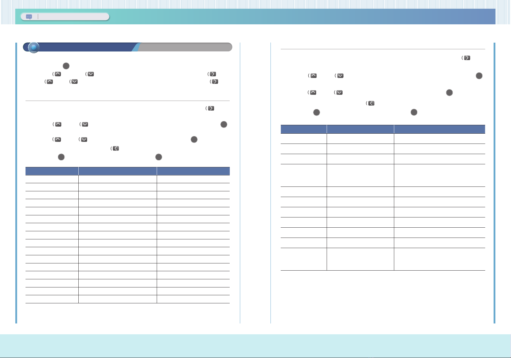
▶ OCGR Setting Method
① After selecting ‘OCGR (50N/51N)’ in Protection Relay Element Setting Method ③, press the RIGHT (
) Key to
enter the setting screen.
② Use the UP ( ), DOWN ( ) KEY to move the category you want to set, and then enter the ENTER (
ENTER
)
KEY to pop up the password input screen. (initial password 0000)
③ Use the UP ( ), DOWN ( ) KEY to change the setting value and then input ENTER (
ENTER
) KEY.
④ After completing the setting, input the LEFT (
) KEY to check whether the setting has been changed.
When ENTER (
ENTER
) KEY is input, the setting is saved, and when ESC (
ESC
) KEY is input, the setting is canceled.
Category Setting Range Description
FUNCTION DISABLED, ENABLED Whether to use the function
ID NAME 8 ASCII Characters Protection element name setting
ALGORITHM PHASOR, RMS Relay calculation method setting
PICKUP 0.02 ~ 20.00pu (0.01pu STEP) Pickup setting
MODE INST, DT, INV Operation mode setting
TIME DELAY 0.04 ~ 60.00s (0.01s STEP) Operation delay time setting
CURVE IEC_NI, .... IEEE_MI Inverse curve setting
LEVER 0.01 ~ 10.00 (0.01 STEP) Inverse lever setting
RESET DLY 0.00 ~ 60.00s (0.01s STEP) Reset delay time setting
BLOCK NONE, .... R/I16 Protection blocking condition setting
DO1-CB OPN DISABLED, ENABLED DO1 setting
DO2-CB CLS DISABLED, ENABLED DO2 setting
DO3 DISABLED, ENABLED DO3 setting
DO4 DISABLED, ENABLED DO4 setting
LED NONE, ALARM, LED#1 ~ #8 LED setting
EVENT DISABLED, OP, PKP+OP, OP+RST, ALL EVENT record setting
Category Setting Range Description
FUNCTION DISABLED, ENABLED Setting whether to use the function
ID NAME 8 ASCII Characters Protection element name setting
ALGORITHM PHASOR, RMS Relay calculation method setting
SOURCE 3I0, NCT
Zero sequence current source setting
3I0 : Internal calculation
NCT : N phase current
PICKUP 0.02 ~ 20.00pu (0.01pu STEP) Pickup setting
MODE INST, DT, INV Operation mode setting
TIME DELAY 0.04 ~ 60.00s (0.01s STEP) Operation delay time setting
CURVE IEC_NI, .... IEEE_MI Inverse curve setting (12ea)
LEVER 0.01 ~ 10.00 (0.01 STEP) Inverse lever setting
RESET DLY 0.00 ~ 60.00s (0.01s STEP) Reset delay time setting
I1 RESTRAINT DISABLED, ENABED
Setting whether to use the current restraint
function
※ Excluding single phase relay
- Among the OCR setting methods, BLOCK ~ EVENT setting category are the same setting category for all protection
elements.
① Press the MENU(
MENU
) key on the initial screen
② Use the UP ( ) and DOWN ( ) keys to select ‘1. RELAY SETTING’ category, then input RIGHT (
) Key.
③ Use UP ( ), DOWN ( ) KEY to select the protection relay element to be set and then input the RIGHT (
) Key.
▶ OCR Setting Method
① After selecting ‘OCR1 (50/51)’ in Protection Relay Element Setting Method ③, press the RIGHT (
) Key to
enter the setting screen.
② Use the UP ( ), DOWN ( ) KEY to move the category you want to set, and then enter the ENTER (
ENTER
)
KEY to pop up the password input screen. (initial password 0000)
③ Use the UP ( ), DOWN ( ) KEY to change the setting value and then input ENTER (
ENTER
) KEY.
④ After completing the setting, input the LEFT (
) KEY to check whether the setting has been changed.
When ENTER (
ENTER
) KEY is input, the setting is saved, and when ESC (
ESC
) KEY is input, the setting is canceled.
다기능 디지털 복합 보호계전기 K-PAM 5500 Series
16 17
Kyongbo Electric Co., Ltd.
Digital Integrated Protection Relay K-PAM 10 Series
Category Setting Range Description
FUNCTION DISABLED, ENABLED Setting whether to use the function
ID NAME 8 ASCII Characters Protection element name setting
PICKUP 0.02 ~ 20.00pu (0.01pu STEP) Pickup setting
BLOCK VOLT 0.02 ~ 1.30pu (0.01pu STEP) Minimum operating voltage setting
RCA 0 ~ 359° (1° STEP) Reference phase angle setting
DIRECTION FORWARD, REVERSE Operation direction setting
MODE INST, DT, INV Operation mode setting
TIME DELAY 0.04 ~ 60.00s (0.01s STEP) Operation delay time setting
CURVE IEC_NI, .... IEEE_MI Inverse curve setting (12ea)
LEVER 0.01 ~ 10.00 (0.01 STEP) Inverse lever setting
RESET DLY 0.00 ~ 60.00s (0.01s STEP) Reset delay time setting
Category Setting Range Description
FUNCTION DISABLED, ENABLED Setting whether to use the function
ID NAME 8 ASCII Characters Protection element name setting
CURR SRC 3I0, NCT
Zero sequence current source setting
3I0 : Internal calculation
NCT : N phase current
PICKUP 0.02 ~ 20.00pu (0.01pu STEP) Pickup setting
POL VOLT SRC 3V0, EVT
Zero sequence voltage source setting
3V0 : Internal calculation
EVT : N phase current
BLOCK VOLT 0.10 ~ 1.50pu (0.01pu STEP) Minimum operating voltage setting
RCA 0 ~ 359° (1° STEP) Reference phase angle setting
OLA 30 ~ 87° (1° STEP) Operation phase angle setting
DIRECTION FORWARD, REVERSE Operation direction setting
MODE INST, DT, INV Operation mode setting
TIME DELAY 0.04 ~ 60.00s (0.01s STEP) Operation delay time setting
CURVE IEC_NI, .... IEEE_MI Inverse curve setting (12ea)
LEVER 0.01 ~ 10.00 (0.01 STEP) Inverse lever setting
RESET DLY 0.00 ~ 60.00s (0.01s STEP) Reset delay time setting
I1 RESTRAINT 0.000 ~ 0.500 (0.001 STEP) Current restraint constant setting
※ Excluding single phase relay
▶ DOCGR Setting Method
① After selecting ‘DOCGR (67N)’ in Protection Relay Element Setting Method ③, press the RIGHT ( ) Key to
enter the setting screen.
② Use the UP ( ), DOWN ( ) KEY to move the category you want to set, and then enter the ENTER ( )
KEY to pop up the password input screen. (initial password 0000)
③ Use the UP ( ), DOWN ( ) KEY to change the setting value and then input ENTER (
ENTER
) KEY.
④ After completing the setting, input the LEFT (
) KEY to check whether the setting has been changed.
When ENTER (
ENTER
) KEY is input, the setting is saved, and when ESC (
ESC
) KEY is input, the setting is canceled.
▶ DOCR Setting Method
① After selecting ‘DOCR (67)’ in Protection Relay Element Setting Method ③, press the RIGHT (
) Key to enter
the setting screen.
② Use the UP ( ), DOWN ( ) KEY to move the category you want to set, and then enter the ENTER (
ENTER
)
KEY to pop up the password input screen. (initial password 0000)
③ Use the UP ( ), DOWN ( ) KEY to change the setting value and then input ENTER (
ENTER
) KEY.
④ After completing the setting, input the LEFT (
) KEY to check whether the setting has been changed.
When ENTER (
ENTER
) KEY is input, the setting is saved, and when ESC (
ESC
) KEY is input, the setting is canceled.
다기능 디지털 복합 보호계전기 K-PAM 5500 Series
18 19
Kyongbo Electric Co., Ltd.
Digital Integrated Protection Relay K-PAM 10 Series
Category Setting Range Description
FUNCTION DISABLED, ENABLED Setting whether to use the function
ID NAME 8 ASCII Characters Protection element name setting
PICKUP 0.20 ~ 1.30pu (0.01pu STEP) Pickup setting
BLOCK VOLT 0.00 ~ 1.60pu (0.01pu STEP) Minimum operating voltage setting
AUTO RESET DISABLED, ENABLED Auto Reset Setting
MODE INST, DT, INV Operation mode setting
TIME DELAY 0.04 ~ 60.00s (0.01s STEP) Operation delay time setting
CURVE IEC_NI, .... IEEE_MI Inverse curve setting
LEVER 0.01 ~ 10.00 (0.01 STEP) Inverse lever setting
RESET DLY 0.00 ~ 60.00s (0.01s STEP) Reset delay time setting
Category Setting Range Description
FUNCTION DISABLED, ENABLED Setting whether to use the function
ID NAME 8 ASCII Characters Protection element name setting
SOURCE 1P, 1Q, 3P, 3Q Operation Element Setting
※ Single phase relay : 1P, 1Q
DIRECTION NONE, FORWARD, REVERSE Operation direction setting
PICKUP 0.01 ~ 1.50pu (0.01pu STEP) Pickup setting
MODE DT, INV Operation mode setting
TIME DELAY 0.04 ~ 60.00s (0.01s STEP) Operation delay time setting
CURVE OPR INV1, OPR INV2, RePR INV Inverse curve setting(3ea)
LEVER 0.01 ~ 10.00 (0.01 STEP) Inverse lever setting
RESET DLY 0.00 ~ 60.00s (0.01s STEP) Reset delay time setting
▶ UVR Setting Method
① After selecting ‘UVR (27)’ in Protection Relay Element Setting Method ③, press the RIGHT (
) Key to enter
the setting screen.
② Use the UP ( ), DOWN ( ) KEY to move the category you want to set, and then enter the ENTER (
ENTER
)
KEY to pop up the password input screen. (initial password 0000)
③ Use the UP ( ), DOWN ( ) KEY to change the setting value and then input ENTER (
ENTER
) KEY.
④ After completing the setting, input the LEFT (
) KEY to check whether the setting has been changed.
When ENTER (
ENTER
) KEY is input, the setting is saved, and when ESC (
ESC
) KEY is input, the setting is canceled.
▶ DPR Setting Method
① After selecting ‘DPR (32P/Q)’ in Protection Relay Element Setting Method ③, press the RIGHT (
) Key to
enter the setting screen.
② Use the UP ( ), DOWN ( ) KEY to move the category you want to set, and then enter the ENTER (
ENTER
)
KEY to pop up the password input screen. (initial password 0000)
③ Use the UP ( ), DOWN ( ) KEY to change the setting value and then input ENTER (
ENTER
) KEY.
④ After completing the setting, input the LEFT (
) KEY to check whether the setting has been changed.
When ENTER (
ENTER
) KEY is input, the setting is saved, and when ESC (
ESC
) KEY is input, the setting is canceled.
▶ DPR Setting Example
- Generally, about 20% of the generated electricity is applied.
- When the power generation capacity is 100kW, EVT 380V / 190V, CT 1000/5A
Power generation capacity ÷ VT ratio ÷ CT ratio × 0.2 ⇒ 100kW ÷ 2 ÷ 200 × 0.2 = 50W
1pu: 190V × 5A = 950W, 50W ÷ 950W ≒ 0.05pu
다기능 디지털 복합 보호계전기 K-PAM 5500 Series
20 21
Kyongbo Electric Co., Ltd.
Digital Integrated Protection Relay K-PAM 10 Series
Category Setting Range Description
FUNCTION DISABLED, ENABLED Setting whether to use the function
ID NAME 8 ASCII Characters Protection element name setting
PICKUP 47.00 ~ 65.00Hz (0.01Hz STEP) Operation frequency setting
BLOCK VOLT 0.02 ~ 1.30pu (0.01pu STEP) Minimum operating voltage setting
TIME DELAY 0.04 ~ 60.00s (0.01s STEP) Operation delay time setting
RESET DLY 0.00 ~ 60.00s (0.01s STEP) Reset delay time setting
Contact Output Test Method
① Press the MENU(
MENU
) key on the initial screen
② Use the UP ( ) and DOWN ( ) keys to move the ‘6.DEVICE CONFIG’ category, and then press the RIGHT
(
) Key.
③ Use the UP ( ) and DOWN ( ) keys to move the ‘11.TEST’ category, and then press the RIGHT (
) Key.
④ Use the UP ( ) and DOWN ( ) keys to move the ‘2.D/O TEST’ category, and then press the RIGHT (
) Key.
After the password input screen pops up (Initial password 0000), enter the digital output TEST screen when
ENTER KEY is input.
LCD SCREEN
D / O T E S T 1 / 2
⇒ 1 . D / O # 1 : O f f
2 . D / O # 2 : O f f
3 . D / O # 3 : O f f
D / O T E S T 2 / 2
4 . D / O # 4 : O f f
5 . D / O # 5 : O f f
TEST Method
(1) In the D/O TEST screen, press the UP( ), DOWN( ) keys and press the ENTER(
ENTER
) key at the
position of the contact to be tested, the contact will change from Off to On and the contact will be output.
When the ESC(
ESC
) key is pressed, the output contact is reset.
(2) If you press the UP( ) or DOWN( ) KEY, you can select another digital output.
In this state, if you press the LEFT (
) KEY, all the contacts will return to original state and come out
of the screen.
▶ UFR Setting Method
① After selecting ‘UFR (81U)’ in Protection Relay Element Setting Method ③, press the RIGHT (
) Key to enter
the setting screen.
② Use the UP ( ), DOWN ( ) KEY to move the category you want to set, and then enter the ENTER ( )
KEY to pop up the password input screen. (initial password 0000)
③ Use the UP ( ), DOWN ( ) KEY to change the setting value and then input ENTER (
ENTER
) KEY.
④ After completing the setting, input the LEFT (
) KEY to check whether the setting has been changed.
When ENTER (
ENTER
) KEY is input, the setting is saved, and when ESC (
ESC
) KEY is input, the setting is canceled.
How to check when the operation of the protection element (In case of fault)
①Check the Front
Fault is being held
The protection element is in operation, but the fault has reset.
② Check the protection relay element status window
- Press the MENU(
MENU
) key on the initial screen
- Use the UP ( ) and DOWN ( ) keys to move the ‘4.STATUS’ category, and then press the RIGHT (
) Key.
- Use the UP ( ) and DOWN ( ) keys to move the ‘1.PROT STATUS category, and when RIGHT (
) Key is
input, the following screen is displayed.
다기능 디지털 복합 보호계전기 K-PAM 5500 Series
22 23
Kyongbo Electric Co., Ltd.
Digital Integrated Protection Relay K-PAM 10 Series
③ Log Check
- Event Record Check
- 사고기록 및 사고파형 확인
LCD Screen Screen Description
- Save up to 512 EVENT occurrence information
- Displays power ON/OFF, protection element
operation status, digital input/output status, CB
control, set value change, etc.
LCD Screen Screen Description
- Save up to 32 FAULT occurrence information
- Displays the PICK-UP, OPERATE, RELEASE,
operation time, fundamental wave (voltage,
current, etc.) magnitude, phase, frequency, etc.
- Save up to 4 fault waveform
(64 Cycles, 1.06 sec)
Check it by uploading it on-site or from a remote
location through KBIED_MNE.
E V E N T 0 0 9 / 5 1 2
2 1 0 7 0 6 1 0 : 2 2 : 3 2 . 0 8 1
O C R 1 O P
F A U L T 0 1 / 3 2 ( W A V E )
2 1 0 7 0 6 1 0 : 2 2 : 3 2 . 0 8 1
O C R 1 O P
D U R A T I O N : 0 . 0 4 s
LCD Screen Screen Description
Protection element not operating
Over current (OCR1) element fault occurred and
the current higher than the set value is maintained
but does not operate.
(The output contact is not operate)
Over current (OCR1) element fault occurred
and the current higher than the set value is
maintained, so the protection element is in
operation and the output contact is in operation.
Over current (OCR1) element fault occurred and
the output contact operated, but the fault current
disappeared.
P R O T S T A T U S : P K P : O P
1 . O C R 1 : :
2 . O C G R 1 : :
3 . D O C G R : :
P R O T S T A T U S : P K P : O P
1 . O C R 1 : A B C :
2 . O C G R 1 : :
3 . D O C G R : :
P R O T S T A T U S : P K P : O P
1 . O C R 1 : A B C : A B C
2 . O C G R 1 : :
3 . D O C G R : :
P R O T S T A T U S : P K P : O P
1 . O C R 1 : : A B C
2 . O C G R 1 : :
3 . D O C G R : :
How to check measurement after field intallation
① After installing the product in the field, check the measured value when receiving power to check the normal state.
② Press the MENU(
MENU
) KEY on the initial screen.
③ Use the UP ( ), DOWN ( ) key to select ‘2. MEASUREMENT’ and then input the RIGHT (
) Key.
④ Use the UP ( ) and DOWN ( ) keys to select ‘1. VOLTAGE’ and input the RIGHT (
) Key to check the
voltage measurement.
⑤ Use UP ( ), DOWN ( ) KEY to check other measurements.
LCD Screen
M E A S U R E M E N T 1 / 1
⇒ 1 . V O L T A G E
2 . C U R R E N T
3 . P O W E R
V O L T A G E 1 / 2
V a : 1 1 0 . 0 0 0 V ∠ 0 . 0
V b : 1 1 0 . 0 0 0 V ∠ 2 4 0 . 0
V c : 1 1 0 . 0 0 0 V ∠ 1 2 0 . 0
C U R R E N T 1 / 2
I a : 1 . 2 0 0 A ∠ 3 0 . 0
I b : 1 . 2 0 0 A ∠ 2 7 0 . 0
I c : 1 . 2 0 0 A ∠ 1 5 0 . 0
CAUTION
• In a normal case, the magnitude of voltage and current may be different, and the phase should be
displayed with a value similar to the example shown above for normal wiring.
• A phase voltage is the standard for phase display, and the magnitude of voltage/current/power indicates
the primary value to which RATIO is applied.
(In case of F10 without voltage A phase, current A phase is the phase reference)
• In the case of a directional element, since it operates with the magnitude and phase of voltage and
current, malfunction or non-operation may occur if it is not in the normal phase.
• If the measured value is out of phase, check the primary wiring and the VT, CT secondary wiring.
다기능 디지털 복합 보호계전기 K-PAM 5500 Series
24 25
Kyongbo Electric Co., Ltd.
Digital Integrated Protection Relay K-PAM 10 Series
K-PAM DG10
T2-2
T2-1 T1-3
T1-4
T1-1
T1-2
T1-7
T1-5
50/51,
50N/51N,
67, 67N, 32P
T1-6
59, 27, 64,
81O/U, 81R
T1-8
R.F
DO2 DO1 DO3 DO4 DO5
POWER
VCB
52
T1-10 T1-11
T1-13
RG
P1
N1
CLOSING TRIPPING
VCB
VCB DC SEQUENCE DIAGRAM
VCB ON
VCB OFF
ON OFF
CS
MCCB 2P
30/20AT CS
OFF ON
DC
110V
P
N
P1
N1
T1-9
K-PAM S10
T2-2
T2-1 T1-3
T1-4
T1-1
T1-2
T1-7
T1-5
50/51,
50N/51N,
67N, 67G,
32P
T1-6
59, 27, 64
T1-8
R.F
DO2 DO1 DO3 DO4 DO5
POWER
VCB
52
T1-10 T1-11
T1-13
RG
P1
N1
CLOSING TRIPPING
VCB
VCB DC SEQUENCE DIAGRAM
VCB ON
VCB OFF
ON OFF
CS
MCCB 2P
30/20AT CS
OFF ON
DC
110V
P
N
P1
N1
T1-9
K-PAM V10
T2-2
T2-1 T1-3
T1-4
T1-1
T1-2
T1-7
T1-5
59, 27, 64
T1-6
47P, 47N,
81O/U, 81R
T1-8
R.F
DO2 DO1 DO3 DO4 DO5
POWER
VCB
52
T1-10 T1-11
T1-13
RG
P1
N1
CLOSING TRIPPING
VCB
VCB DC SEQUENCE DIAGRAM
VCB ON
VCB OFF
ON OFF
CS
MCCB 2P
30/20AT CS
OFF ON
DC
110V
P
N
P1
N1
T1-9
K-PAM F10
T2-2
T2-1 T1-3
T1-4
T1-1
T1-2
T1-7
T1-5
50/51,
50N/51N,
46U
T1-6
67N, 67G,
64
T1-8
R.F
DO2 DO1 DO3 DO4 DO5
POWER
VCB
52
T1-10 T1-11
T1-13
RG
P1
N1
CLOSING TRIPPING
VCB
VCB DC SEQUENCE DIAGRAM
VCB ON
VCB OFF
ON OFF
CS
MCCB 2P
30/20AT CS
OFF ON
DC
110V
P
N
P1
N1
T1-9
K-PAM M11
T2-2
T2-1 T1-3
T1-4
T1-1
T1-2
T1-7
T1-5
50/51,
50N/51N,
46U, 49
T1-6
59, 27, 64,
47N
T1-8
R.F
DO2 DO1 DO3 DO4 DO5
POWER
VCB
52
T1-10 T1-11
T1-13
RG
P1
N1
CLOSING TRIPPING
VCB
VCB DC SEQUENCE DIAGRAM
VCB ON
VCB OFF
ON OFF
CS
MCCB 2P
30/20AT CS
OFF ON
DC
110V
P
N
P1
N1
T1-9
K-PAM M10
T2-2
T2-1 T1-3
T1-4
T1-1
T1-2
T1-7
T1-5
50/51, 67G,
46U, 49
T1-6
59, 27, 64,
47N
T1-8
R.F
DO2 DO1 DO3 DO4 DO5
POWER
VCB
52
T1-10 T1-11
T1-13
RG
P1
N1
CLOSING TRIPPING
VCB
VCB DC SEQUENCE DIAGRAM
VCB ON
VCB OFF
ON OFF
CS
MCCB 2P
30/20AT CS
OFF ON
DC
110V
P
N
P1
N1
T1-9
󱇲 K-PAM DG10 VCB DC Sequence (example drawing)
K-PAM 10Series Control Circuit Diagram
󱇲 K-PAM DG10 AC Sequence (example drawing)
※ For each product, the D/O, D/I, RS485, and control power terminals are the same, but the current/voltage input terminals
are different. Check the wiring diagram before wiring.
FAQ
⑴ Although the circuit breaker is open, UVR contact output is not operating.
- If you go to the UVR setting item, there is a BLOCK VOLT setting.
This category sets the minimum operating voltage at which UVR operates. For example, if the BLOCK VOLT setting is
0.20pu and the PICKUP setting is 0.8pu, it does not operate when the voltage is below 0.2pu and only operate at a
voltage between 0.2pu and 0.8pu.
Check the settings and change them according to the site conditions.
⑵ Does frequency measure all three-phase voltages?
- Frequency measurement is the frequency of A-phase voltage.
⑶ dF/dT(81R) test does not operate even if the applied frequency is raised or lowered a lot
- When setting dF/dT to +1.0Hz, 0.3 sec, MIN V1 : 80V, the test applied voltage and frequency are 1 ÷ 0 6 ≒ 0.016[Hz],
and the frequency changed by 0.02Hz or more per at least 1 cycle is about 20 cycles (about 0.3 sec) for voltage A.
At this time, the voltage should be at least 80V.
⑷ How can the user directly change the contact settings?
- When entering the setting category of the protection element and setting the DO1~DO4 setting category to
ENABLED, if the protection element operates, the contact set to ENABLED can be output.
⑸ When the relay is installed on the panel and tested, the measured value is displayed less than the applied
current.
- Please refer to the install/withdraw method in this user's manual.
Since the enclosure and relay are drawn out, normal measurement may not be possible if the enclosure is installed
incorrectly.
⑹ Normally during solar power generation, the measured current of the relay and the measured current
measured with a clamp meter are different.
- The digital relay measures and displays only the fundamental wave excluding the harmonic content. However, most
general clamp meters and multimeters measure values including harmonic content, which may result in different
measured values between products.
⑺ During solar power generation, the power value displayed by the relay and the power value displayed by
the inverter are different.
- Move to the menu / POWER SYSTEM category and check the VT, CT 1st and 2nd ratios to see if the settings are
different from the inverter settings.
Since the values of voltage and current applied to the product are internally calculated with the values set above and
displayed as the primary value, you must check the settings and change them when they are set to different settings.
다기능 디지털 복합 보호계전기 K-PAM 5500 Series
26 27
Kyongbo Electric Co., Ltd.
Digital Integrated Protection Relay K-PAM 10 Series
D/O1_NO
1
2
3
4
5
6
7
8
9
14 +
15
16
-
COM
RS-485
1
2
V
A
3
4
5
6
8
7
V
B
V
C
V
N
9
10
I
A
11
12
13
14
15
16
IB
IC
IN
+
-
+
-
+
-
-
+
+
-
+
-
+
-
+
-
C
L
R
EVT
Terminal : T1
D/O1_COM
D/O3_NO
D/O5_NC
D/O5_COM
D/I1_NO
10
11
12
13
Terminal : T1
D/I2_NO
D/I3_NO
D/I1~3_COM
Terminal : T3
Terminal : T3
Terminal : T1
D/O4_NO
D/O3~4_COM
D/O2_NO
D/O2_COM
Aux. Power 1
2
+
-
=
~
Terminal : T2
FG 3
CHASSIS
DG10
CT
A
(L1)
B
(L2)
C
(L3)
K-PAM 10Series External Wiring
󱇲 DG10
󱇲 S10
D/O1_NO
1
2
3
4
5
6
7
8
9
14 +
15
16
-
COM
RS-485
1
2
V
A
3
4
5
6
8
7
V
B
V
C
V
N
+
-
+
-
+
-
-
+C
L
R
EVT
Terminal : T1
D/O1_COM
D/O3_NO
D/O5_NC
D/O5_COM
D/I1_NO
10
11
12
13
Terminal : T1
D/I2_NO
D/I3_NO
D/I1~3_COM
Terminal : T3
Terminal : T1
D/O4_NO
D/O3~4_COM
D/O2_NO
D/O2_COM
Aux. Power 1
2
+
-
=
~
Terminal : T2
FG 3
CHASSIS
V10
A
(L1)
B
(L2)
C
(L3)
D/O1_NO
1
2
3
4
5
6
7
8
9
14 +
15
16
-
COM
RS-485
8
7
V
N
I
A
IB
IC
IN
-
+
+
-
+
-
+
-
+
-
C
L
R
EVT
Terminal : T1
D/O1_COM
D/O3_NO
D/O5_NC
D/O5_COM
D/I1_NO
10
11
12
13
Terminal : T1
D/I2_NO
D/I3_NO
D/I1~3_COM
Terminal : T3
Terminal : T1
D/O4_NO
D/O3~4_COM
D/O2_NO
D/O2_COM
Aux. Power 1
2
+
-
=
~
Terminal : T2
FG 3
CHASSIS
F10
5
6
IG
+
-
Terminal : T3
9
10
11
12
13
14
15
16
CT
ZCT
A
(L1)
B
(L2)
C
(L3)
󱇲 V10
󱇲 F10
D/O1_NO
1
2
3
4
5
6
7
8
9
14 +
15
16
-
COM
RS-485
1
2
V+
-
Terminal : T1
D/O1_COM
D/O3_NO
D/O5_NC
D/O5_COM
D/I1_NO
10
11
12
13
Terminal : T1
D/I2_NO
D/I3_NO
D/I1~3_COM
Terminal : T3
Terminal : T1
D/O4_NO
D/O3~4_COM
D/O2_NO
D/O2_COM
Aux. Power 1
2
+
-
=
~
Terminal : T2
FG 3
CHASSIS
S10
5
6
Iz+
-
C상
VT
3
4
I+
-
B상
C상
Terminal : T3
Terminal : T3
2
1
VO-
+C
L
R
EVT
Terminal : T3
SGR & DGR 사용시 결선
전압 및 전력요소 사용시 결선
ZCT
CT
A
(L1)
B
(L2)
C
(L3)
Wiring when using voltage and power protection
Wiring when using SGR & DGR
다기능 디지털 복합 보호계전기 K-PAM 5500 Series
28 29
Kyongbo Electric Co., Ltd.
Digital Integrated Protection Relay K-PAM 10 Series
D/O1_NO
1
2
3
4
5
6
7
8
9
14 +
15
16
-
COM
RS-485
1
2
V
A
3
4
5
6
8
7
V
B
V
C
V
N
I
A
IB
IC
IN
+
-
+
-
+
-
-
+
+
-
+
-
+
-
+
-
C
L
R
EVT
Terminal : T1
D/O1_COM
D/O3_NO
D/O5_NC
D/O5_COM
D/I1_NO
10
11
12
13
Terminal : T1
D/I2_NO
D/I3_NO
D/I1~3_COM
Terminal : T3
Terminal : T3
Terminal : T1
D/O4_NO
D/O3~4_COM
D/O2_NO
D/O2_COM
Aux. Power 1
2
+
-
=
~
Terminal : T2
FG 3
CHASSIS
M11
9
10
11
12
13
14
15
16
CT
A
(L1)
B
(L2)
C
(L3)
D/O1_NO
1
2
3
4
5
6
7
8
9
14 +
15
16
-
COM
RS-485
1
2
V
A
3
4
5
6
8
7
V
B
V
C
V
N
I
A
IB
IC
+
-
+
-
+
-
-
+
+
-
+
-
+
-
C
L
R
EVT
Terminal : T1
D/O1_COM
D/O3_NO
D/O5_NC
D/O5_COM
D/I1_NO
10
11
12
13
Terminal : T1
D/I2_NO
D/I3_NO
D/I1~3_COM
Terminal : T3
Terminal : T3
Terminal : T1
D/O4_NO
D/O3~4_COM
D/O2_NO
D/O2_COM
Aux. Power 1
2
+
-
=
~
Terminal : T2
FG 3
CHASSIS
M10
IZ
+
-
9
10
11
12
13
14
15
16
CT
ZCT
A
(L1)
B
(L2)
C
(L3)
󱇲 M11
󱇲 M10
•Can replace GD Series, GDR Series, Induction Relay, K-PAM F300 without separate panel processing.
󱇱 Front
󱇱 Rear
󱇱 Side
󱇱 Panel Dimensions
K-PAM 10Series Dimensions
04792
5, Seongsuil-ro 12ga-gil, Seongdong-gu,
Seoul, Republic of Korea
Tel : 02)465 -1133~ 7 Fax : 02) 465-1333
E-mail : [email protected]
Website : http://www.kyongbo.co.kr
Kyongbo Electric Co., Ltd. A/S
02)465-1133
(extension 102)
K-PAM 10Series Install/withdraw Method
•Install/withdraw Method
① Attach the enclosure to the panel cut to fit the product.
② Assemble by tightening the enclosed nuts to the four bolts on the corners of the enclosure mounted on the panel.
③ Remove the handle cover of the product, loosen the screw, raise the handle vertically as shown in ④, and attach it to the
enclosure.
⑤ After inserting the product into the enclosure, lower the handle so that the assembly and the enclosure are in close
contact. After tightening the screw loosened in ③, assemble the handle cover.
When withdrawing a product, you can withdraw the product by proceeding in the reverse order of the above. Before
withdrawing, remove the connectors connected to T1 and T2 on the back of the product before withdrawing.
•Install/withdraw Method
① 제품에 맞게 커팅된 판넬에 외함을 취부합니다.
② 판넬에 취부된 외함 모서리 4개의 볼트에 동봉된 너트를 조여 조립합니다.
③ 제품의 손잡이 커버를 제거하여 나사를 풀어 ④와 같이 손잡이를 수직으로 올린 후 외함에 취부합니다.
⑤ 제품을 외함에 취부한 상태로 밀어 넣은 후 손잡이를 아래로 내려 외함과 조립이 밀착되도록 하고
③에서 푼 나사를 조인 후 손잡이 커버를 조립합니다.
제품 인출 시 위 순서와 반대로 진행하여 제품을 인출 할 수 있으며 인출 전 제품 후면의 T1, T2에 연결된
CONNECTOR를 분리 후 인출 하십시오.
K-PAM 10 Series
Digital Integrated Protection Relay
User Manual

Other manuals for K-PAM 10 Series

1

This manual suits for next models

6

Other Kyongbo Electric Relay manuals

Kyongbo Electric K-PAM 10 Series User manual

Kyongbo Electric

Kyongbo Electric K-PAM 10 Series User manual

Kyongbo Electric K-PAM 5500 Series User manual

Kyongbo Electric

Kyongbo Electric K-PAM 5500 Series User manual

Kyongbo Electric GDR-M02 User manual

Kyongbo Electric

Kyongbo Electric GDR-M02 User manual

Popular Relay manuals by other brands

Edwards A07199041 instruction manual

Edwards

Edwards A07199041 instruction manual

Fideltronik Inigo DTC 400 user manual

Fideltronik Inigo

Fideltronik Inigo DTC 400 user manual

Siemens Siprotec 7UM611 manual

Siemens

Siemens Siprotec 7UM611 manual

Allen-Bradley 193-EF1A Installation instruction

Allen-Bradley

Allen-Bradley 193-EF1A Installation instruction

Schweitzer Engineering Laboratories SEL-700G Series instruction manual

Schweitzer Engineering Laboratories

Schweitzer Engineering Laboratories SEL-700G Series instruction manual

SOUNDLIGHT 3202R Mk6 operating manual

SOUNDLIGHT

SOUNDLIGHT 3202R Mk6 operating manual

Toshiba GRL100-101A instruction manual

Toshiba

Toshiba GRL100-101A instruction manual

ETNA ETR-DT Operation manual

ETNA

ETNA ETR-DT Operation manual

Circutor RGU-10C quick start guide

Circutor

Circutor RGU-10C quick start guide

TE Connectivity SRS4M-2NO quick start guide

TE Connectivity

TE Connectivity SRS4M-2NO quick start guide

Davin DV-14 manual

Davin

Davin DV-14 manual

Elko CRM-100 manual

Elko

Elko CRM-100 manual

Rockwell Automation Allen-Bradley Guardmaster Minotaur MSR127 installation instructions

Rockwell Automation

Rockwell Automation Allen-Bradley Guardmaster Minotaur MSR127 installation instructions

Siemens SIRIUS 3RA1913-2B Original operating instructions

Siemens

Siemens SIRIUS 3RA1913-2B Original operating instructions

Viconics R810 Series instruction manual

Viconics

Viconics R810 Series instruction manual

National Instruments 6509 Programmer's manual

National Instruments

National Instruments 6509 Programmer's manual

LS Industrial Systems GIPAM user manual

LS Industrial Systems

LS Industrial Systems GIPAM user manual

Basler BE1-50/51B-225 instruction manual

Basler

Basler BE1-50/51B-225 instruction manual

manuals.online logo
manuals.online logoBrands
  • About & Mission
  • Contact us
  • Privacy Policy
  • Terms and Conditions

Copyright 2025 Manuals.Online. All Rights Reserved.