Digital Integrated Protection Relay K-PAM 5500 Series
7
Num Category Description
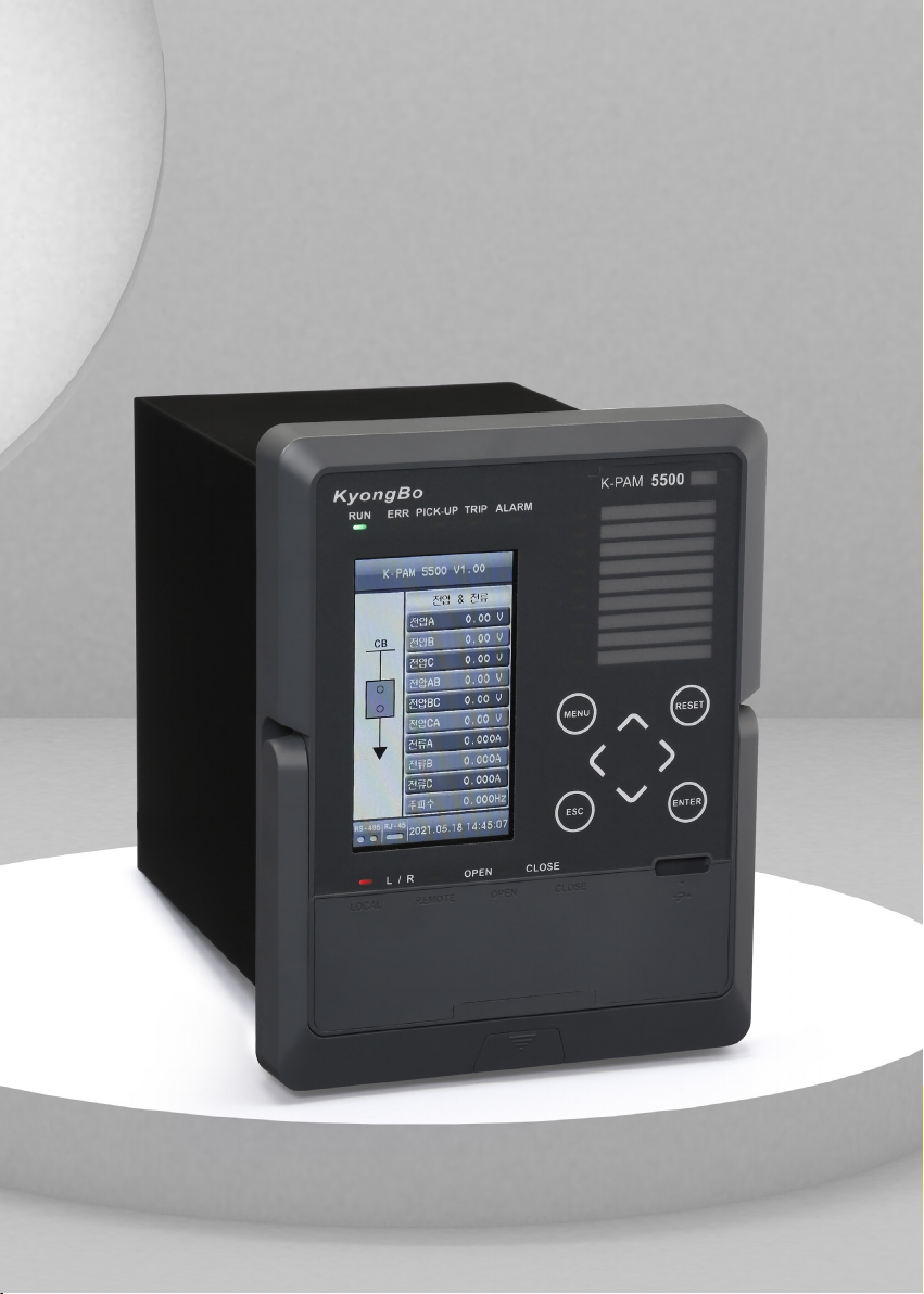
①Status LED
•RUN (GREEN)
- Lights up when the relay is running
•ERROR (RED)
- Lights up when an error occurs as a result of the relay system self-diagnosis
•PICK UP (YELLOW)
- Lights up when the protection relay element is PICK-UP
•TRIP (RED)
- Lights up when the protection relay element is TRIP
•ALARM (YELLOW)
- Lights up when conditions are satisfied by connecting logic
②TFT-LCD •Screen Display
③Local/Remote
Control Button
•L/R Key (LOCAL/ REMOTE Key)
- Used when selecting control operation between Local and Remote
④Custom LED • Use of LED desired by the user through setting of relay protection
element operation, etc.
⑤Button
(UP Key)
- Used to move upwards in a menu category or screen,
increase a number when setting, or change a setting
(Down Key)
- Used to move down on a menu category or screen,
decrease a number when setting, or change a setting
(Right Key)
- Used to move from the menu to the upper menu or to the right when setting
(Left Key)
- Used to move from menu to sub-menu, or to move to the left when setting
MENU Key
- Used to enter the main menu from the initial screen
ESC Key
- Used to cancel setting when setting is in progress or to cancel test in progress
RESET Key
- Displayed as Annunciator Reset when connecting to Logic
- Generally used when reset protection elements OP, LED, and D/O
ENTER Key
- Used to save setting changes or to execute control.
⑥CB Close/Open
Control Button
OPEN Key
- Used when opening CB
CLOSE Key
- Used when closing CB
⑦USB-A Type Port •USB port for connecting relay management software
MENU
ESC
ENTER
OPEN
CLOSE
RESET