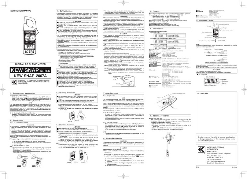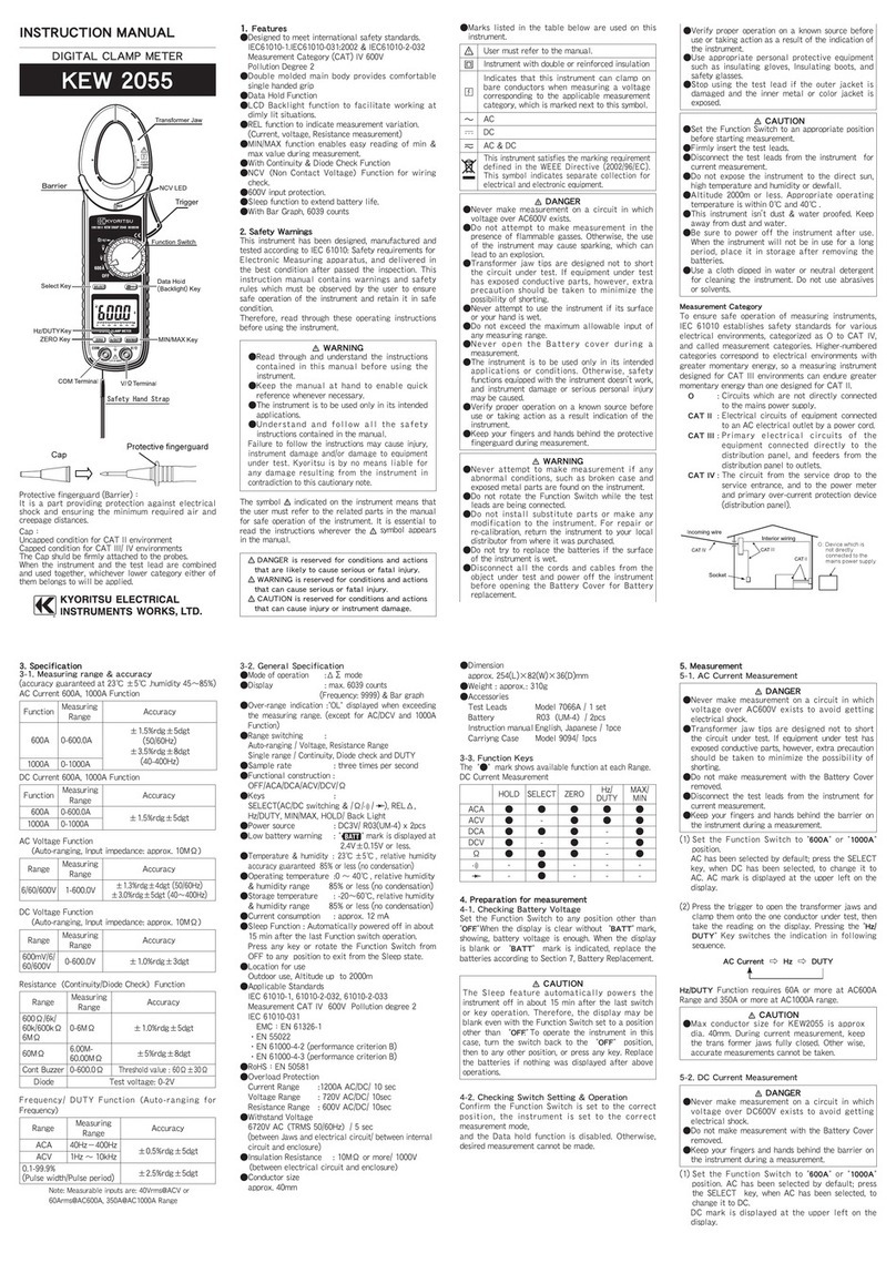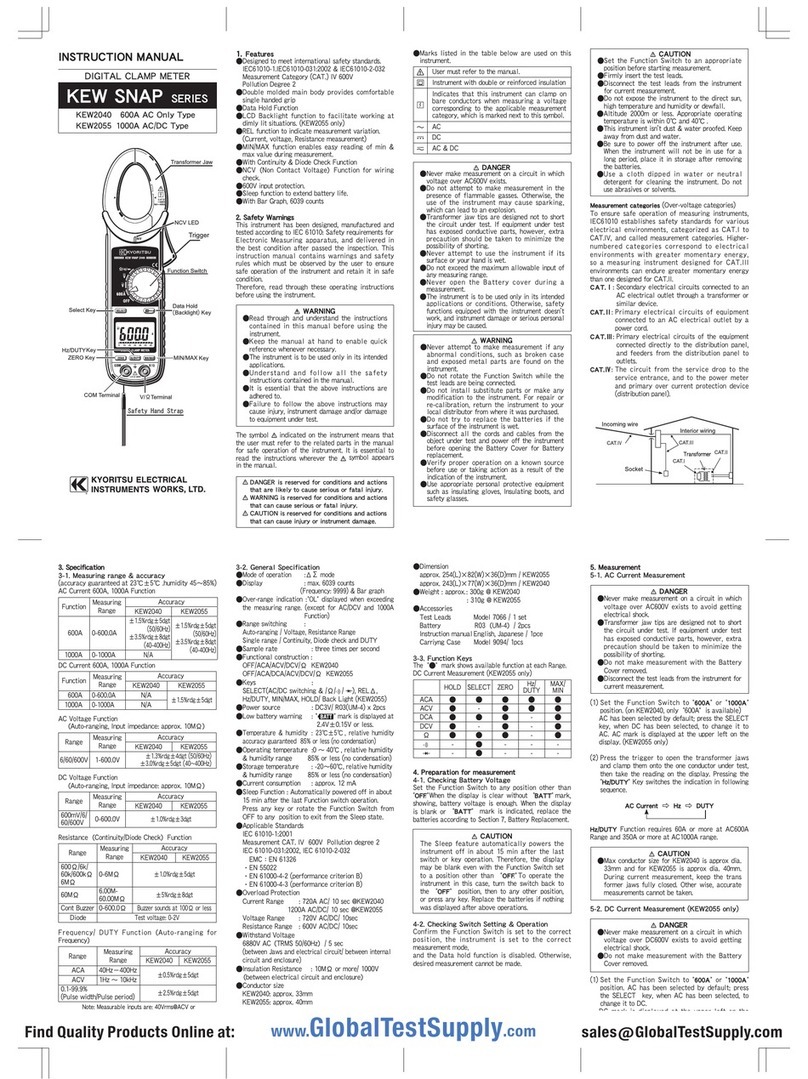
INSTRUCTIONMANUAL
KEW 8146/8147/8148
LEAKAGE CLAMP SENSOR
Series
KYORITSU ELECTRICAL INSTRUMENTS WORKS, LTD.,
TOKYO, JAPAN
KEW
8146
KEW
8147
KEW
8148
LEAKAGECLAMPSENSOR
1. Safety warnings
This instrument has been designed, manufactured and
testedaccordingtoIEC
61010
:Safetyrequirementsfor
Electronic Measuring apparatus, and delivered in the
best condition after passing quality control tests. This
instruction manual contains warnings and safety rules
which have to be observed by the user to ensure safe
operation of the instrument and to maintain it in safe
condition.Therefore,readthroughtheseoperating
instructionsbeforeusingtheinstrument.
# WARNING
●
Read through and understand instructions contained
inthismanualbeforeusingtheinstrument.
●
Keep the manual at hand to enable quick reference
whenevernecessary.
●
The instrument is to be used only in its intended
applications.
The operating instructions described in the manual
mustbeobserved.
●
Understand and follow all the safety instructions
containedinthemanual.
Itisessentialthattheaboveinstructionsareadhered
to.Failuretofollowtheaboveinstructionsmaycause
injuryandorinstrumentdamage.
Thesymbol
#
indicatedontheinstrument,meansthat
theuser mustrefer tothe relatedparts inthe manual
for safe operation of the instrument. It is essential to
readthe instructionswherever the
#
symbol appears
inthemanual.
#
DANGER
isreservedforconditionsandactionsthat
arelikelytocauseseriousorfatalinjury.
#
WARNING
is reserved for conditions and actions
thatcancauseseriousorfatalInjury.
#
CAUTION
isreservedforconditionsandactionsthat
cancauseminorinjuryorinstrumentdamage.
Safetysymbols
Incoming wire
O:Device which is
not directly
connected to the
mains power supply
Socket
Interior wiring
○
MeasurementCategory:
To ensure safe operation of measuring instruments,
IEC
61010
establishes safety standards for various
electrical environments, categorized as O to CAT IV,
and called measurement categories. Higher-numbered
categories correspond to electrical environments with
greater momentary energy, so a measuring instrument
designed for CAT III environments can endure greater
momentaryenergythanonedesignedforCATII.
O :Circuitswhicharenotdirectlyconnected tothe
mainspowersupply.
CATII :Electricalcircuitsofequipmentconnectedtoan
ACelectricaloutletbyapowercord.
CATIII :Primary electrical circuits of the equipment
connecteddirectly tothedistribution panel,and
feedersfromthedistributionpaneltooutlets.
CATIV :The circuit from the service drop to the service
entrance, and to the power meter and primary
over-current protection device (distribution
panel).
2. Features
●
ClampsensorforACleakagecurrentmeasurement.
●
Canmeasureupto:
KEW
8146
:
30
A
KEW
8147
:
70
A
KEW
8148
:
100
A
●
DesignedtointernationalsafetystandardIEC
61010
-
2
-
032
CAT.
Ⅲ
PollutionDegree
2
3. Instrument layout
4. DIN Plug pin assignment
3
:GNDpin
5
:Outputsignalpin
6
:SensorSignalpin
(
Resistancebetween
3
Pinand
6
Pin:
8146
:
47
k
Ω
8147
:
8
.
2
k
Ω
8148
:
30
k
Ω)
1
,
2
and
4
:Nouse
*Lower figure shows the pin assignment seeing the Clamp
sensor from output connector part. The figure of the pin
assignment of connection terminal is symmetrical to lower
figure.
5
3
12
4
6
TransformJaws Trigger Cable Outputconnector
Barrier
5. Operating instructions
# DANGER
●
Never make measurement on a circuit in which the
electricalpotentialexceedsAC
300
Vinordertoavoid
possibleshockhazard.
●
Thetransformerjawsaremadeofmetalandtheirtips
are not completely insulated. Be especially careful
about the possible shorting where the measured
objecthasexposedmetalparts.
.
# CAUTION
●
Take sufficient care to avoid shock, vibration or
excessive force when handling the instrument.
Otherwise,preciselyadjustedtransformerjawswillbe
damaged.
●
Whentransformerjawsdonotfullyclose,nevertryto
closethembyforce,butmakethemfreetomoveand
try again. If a foreign substance is stuck in the jaw
tips,removeit.
●
When making current measurements, keep the
transformerjawsfullyclosed.
Otherwise,accuratemeasurementscannotbetaken.
●
Hold the inserting part (except for the cable) and
disconnecttheOutputconnectorfromthemeasuring
instrumentsoasnottocauseabreakinthecord.
●
When measuring current which pulse element is
superposed, differences of the indicated value may
becausedbetweenranges,ifthepeakvalueexceeds
themeasurementrangetoalargeextent.Inthis
case,
the reading at the bigger range should be taken
as a
right value. Sensitive transformer jaws are used for
Leakageclampmeter.Becauseofthecharacteristics
of transformer jaws, which can be opened and
closed, it is impossible to eliminate the interference
of external magnetic field completely. If there is a
presenceofstrongmagneticfield,usetheinstrument
atadistanceasfaraspossiblefromit.Followingare
thetypicalthingsgeneratingmagneticfield.
・
Conductorfedlargecurrent
・
Motor
・
Equipmentwhichhasmagnet
・
Integratingwattmeter
DISTRIBUTOR
#
Refertotheinstructionsinthemanual.
IndicatesaInstrumentwithdoubleorreinforcedinsulation
Indicates that this instrument can clamp on live bare
conductors when the voltage to be tested is below
Circuit- Ground-to-Earthvoltageagainsttheindicated
MeasurementCategory.
~
IndicatesAC
MINIDIN
6
PIN
50
M
Ω
orgreaterat
1000
V
betweenJawandenclosure
betweenenclosureandoutputterminal
betweenJawandoutputterminal
Model
Ratedvoltage
Outputvoltage
Measuringrange
Accuracy
(Input:sinewave)
Temperature&humidityrange
(Guaranteedaccuracy)
Operatingtemperaturerange
Storagetemperaturerange
Maximumpermissibleinput
Output
impedance
Locationforuse
Applicable
standards
Withstand
voltage
Insulation
resistance
ConductorSize
Dimension
Cablelength
Outputterminal
Weight
Accessories
Option
6. Specifications
23
±
5
℃
,relativehumidity:
85
%orless(nocondensation)
0
〜
50
℃
,relativehumidity:
85
%orless(nocondensation)
-
20
〜
60
℃
,relativehumidity:
85
%orless(nocondensation)
Altitudeupto
2000
m,Indoors
IEC
61010
-
1
,IEC
61010
-
2
-
032
MeasurementCAT.
Ⅲ
(
300
Vrms)
Pollutiondegree
2
IEC
61326
-
1
(EMC),EN
50581
(Environmentalstandard)
Approx.
2
m
Instructionmanual
Cablemarker
Approx.
510
g
Approx.
240
g
Approx.
150
g
186
(L)
×
129
(W)
×
53
(D)mm
128
(L)
×
81
(W)
×
36
(D)mm
100
(L)
×
60
(W)
×
26
(D)mm
Approx.
68
mmindiameter(max.)
Approx.
40
mmindiameter(max.)
Approx.
24
mmindiameter(max.)
AC
3470
Vrms(
50
/
60
Hz)for
5
sec.
betweenJawandenclosure
betweenenclosureandoutputterminal
betweenJawandoutputterminal
Approx.
60
Ω
Approx.
100
Ω
Approx.
90
Ω
AC
100
Armscontinuous(
50
/
60
Hz)AC
70
Armscontinuous(
50
/
60
Hz)AC
30
Armscontinuous(
50
/
60
Hz)
0
A
〜
80
A
±
1
.
0
%rdg
±
0
.
1
mV(
50
/
60
Hz)
±
2
.
0
%rdg
±
0
.
2
mV(
40
〜
1
kHz)
80
A
〜
100
A
±
5
.
0
%rdg(
50
/
60
Hz)
±
10
.
0
%rdg(
45
〜
1
kHz)
0
A
〜
15
A
±
1
.
0
%rdg
±
0
.
1
mV(
50
/
60
Hz)
±
2
.
0
%rdg
±
0
.
2
mV(
40
〜
1
kHz)
15
A
〜
30
A
±
5
.
0
%rdg(
50
/
60
Hz)
±
10
.
0
%rdg(
45
〜
1
kHz)
0
A
〜
40
A
±
1
.
0
%rdg
±
0
.
1
mV(
50
/
60
Hz)
±
2
.
0
%rdg
±
0
.
2
mV(
40
〜
1
kHz)
40
A
〜
70
A
±
5
.
0
%rdg(
50
/
60
Hz)
±
10
.
0
%rdg(
45
〜
1
kHz)
AC
0
〜
100
AAC
0
〜
70
AAC
0
〜
30
A
AC
0
〜
5000
mV
(
50
mV/A)
AC
0
〜
3500
mV
(
50
mV/A)
AC
0
〜
1500
mV
(
50
mV/A)
AC
100
Arms(
141
.
4
Apeak)AC
70
Arms(
99
.
0
Apeak)AC
30
Arms(
42
.
4
Apeak)
KEW
8148
KEW
8147
KEW
8146
MODEL
7146
(
Banana
Φ
4
adjusterplug
)
MODEL
7185
(
Extensioncable
)
www.GlobalTestSupply.com
Find Quality Products Online at: sales@GlobalTestSupply.com
