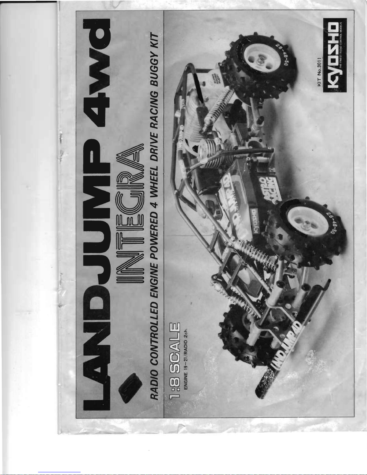
Kyosho Landjump 4wd User manual
Other Kyosho Motorized Toy Car manuals

Kyosho
Kyosho EP FAZER KOBRA User manual

Kyosho
Kyosho MINI-Z Racer AWD MA-010 Type User manual

Kyosho
Kyosho Mini-Z Racer MR-03N HM Type User manual

Kyosho
Kyosho Pro-X 30333 Sport Installation and operating instructions

Kyosho
Kyosho MINI-Z AWD Formula D Series User manual

Kyosho
Kyosho MINI-Z Racer AWD MA-010 Type User manual

Kyosho
Kyosho FAZER FA308 User manual

Kyosho
Kyosho V-one RRR User manual

Kyosho
Kyosho TR15 STADIUM FORCE Readyset User manual

Kyosho
Kyosho FW-05R User manual

Kyosho
Kyosho INFERNO MP7.5 Sports 3 readyset User manual

Kyosho
Kyosho MINI-Z Racer AWD MA-10 Type User manual

Kyosho
Kyosho DRT User manual

Kyosho
Kyosho Inferno GT2 ReadySet User manual

Kyosho
Kyosho MINI-Z Racer MR-03N RM Type User manual

Kyosho
Kyosho MINI-Z Racer MR-03N RM Type User manual

Kyosho
Kyosho DBX Readyset User manual

Kyosho
Kyosho GP TR-15 MONSTER TOURING 4WD User manual

Kyosho
Kyosho INFERNO MP-7.5 Yuichi KANAI EDITION User manual

Kyosho
Kyosho TF-5 Readyset User manual