IM-A-1085E April 2019
GETTING STARTED GUIDE
WGA-680A
INSTRUMENTATION AMPLIFIER
Thank you for purchasing KYOWA s product WGA-680A Instrumentation Amplifier.
Read this Instruction Manual carefully in order to make full use of the high performance capabilities of the
product. Do not use the product in methods other than described in this Manual.
STANDARD ACCESSORIES
The following accessories are packed with the WGA-680A.
When unpacking, check the contents to ensure that all accessories are enclosed.
INSTRUCTION MANUAL 1 (CD-R)
(For WGA-680A, For BCD/RS-232C/RS-485/TEDS, For CC-Link)
Product Warranty 1 each
Unit label 1
Flat-head screw driver for control input/output terminal blocks 1
OPTIONAL ACCESSORIES
100-VAC power cable (length: 2 m) P-23
200-VAC power cable (length: 2 m) P-28
6-conductor NDIS connector input cable U-29 to U-32
4-conductor NDIS connector input cable U-33 to U-36
SAFETY PRECAUTIONS(Do not forget to read the safety precautions prior to use.)
The WGA-680Ais designed to be used according to "INSTRUCTION MANUAL
8. SPECIFICATIONS". Do not use the product in an environment exceeding the specifications. Or, it
may cause troubles.
PRIOR TO USE
For safe use of the product, do not forget to read the "Safety Precautions" prior to use.
KYOWA assumes no liability for any damage resulting from the user's failure to comply with the
safety precautions.
For safety operation of the product, the following symbol marks are used in the Instruction Manual.
Indicates "PROTECTIVE GROUND TERMINAL".
Be sure to connect the GND terminal to the ground.
SAFETY SYMBOLS
For safety operation of the product, the following symbol marks are used in the Instruction Manual.
WARNING Improper operation of the system may result in death or severe injury of
the operator.
CAUTION Improper operation of the system may result in injury of the operator and
physical damage of the system.
WARNING
Warning
Be sure to observe the safety precautions described in the WGA-680AInstruction Manual.
Power supply
To prevent a fire hazard, ensure that the power supply voltage specified for the product
matches the local line voltage before connecting the system to the power outlet.
Power supply specs
WGA-680A-00~04 (AC models) :AC100~240V, Power consumption: 20VA or less
WGA-680A-10~14 (DC models) :DC10~30V, Power consumption: 10W or less
Avoid using in environment with inflammable gas, etc.
To prevent the risk of fire hazard or explosion, do not use the product in environment
with inflammable gas, vapor, or dust.
If any trouble occurs
To prevent a fire hazards, if smoke is emerging from the product, immediately disconnect
the USB cable or AC adapter to terminate the system operation.
Protective ground
Be sure to connect the GND terminal to the ground. Or, it may cause an electric shock hazard,
lower the performance, and cause trouble.
CAUTION
Caution
Be sure to observe the safety precautions described in the WGA-680AInstruction Manual.
Do not use the product outdoors.
Or, it may cause electric shock, fire hazard, lower the performance and cause troubles.
Do not turn ON the power switch immediately after turning it OFF.
After turning OFF the power switch, wait (5 seconds) until the power supply is shut OFF
before turning ON the power switch again.
If the power is repeatedly turned ON and OFF within 5 seconds, rush current generated
by switching the power ON may damage the product.
Use the product within temperature ranging from -10 to +50 .
Use at temperatures exceeding the specified range may lower the performance and cause trouble.
If use under direct sunlight or in a cold place is inevitable, prepare a sunscreen or take proper
measures to keep it warm.
Use the product in the specified operating humidity of 20 to 80% RH.
Use in a humid place exceeding the specified range or where it is exposed to splashing water
may lower the performance and cause trouble.
Do not use the product immediately after the change in the environment.
Leave the product as it is until it becomes adaptable to the environment.
Abrupt change in ambient temperature due to transportation, etc. may cause dew condensation,
which may result in lower performance and troubles.
Use the product under environment without excessive vibration or high impact.
Vibration resistance: 19.6m/s
2
(2G), 10 to 200Hz (when in operation)
Use the product in an area where vibration and impact can be kept within the scope
of specifications.
Continuous vibration or severe impact may cause deteriorated performance and system failure.
Do not use the product in strong electromagnetic field.
Use the product in a magnetic field environment where the PC may be used.
Performance may be lowered and erroneous operation and troubles may result if it is used near
a telemetry system, microwave oven, electronic furnace or any other equipment generating
a strong magnetic field.
Do not use the product under poor conditions.
Operate the product within the range of power supply specs. The power supply used for
the product should not experience an instantaneous power failure and be free from noise.
Do not pull cords and cables.
Lay cords and cables with a certain allowance so that unreasonable force is not applied to the
connections.
Or, it may interrupt the measurements, break the cables, and damage the connectors.
Avoid installing sensors and products near a welding machine.
Failure to do so will pose the risk of erroneous data, malfunction and failure.
Do not disassemble or remodel the product. Or, it may cause electric shock hazards or damage
the product.
This warranty does not cover any damaged or defective parts that results from disassembling or
remodeling.
Do not use or strage the product under dusty or fine particles or corrosive gas environment.
Use or strage under these environment, may result in lower performance and troubles.
Do not expose the product to the air if it is used and stored nearby sea. Air exposure nearby sea
may cause lower performance and products failure.
Take care when handling the CD-R.
Do not expose the CD-R to direct sun light, high temperature, or high humidity.
Do not apply pressure to the CD-R by laying object or bending.
Dust, scratches, and fingerprints on either side of the CD-R can cause write errors.
Preheat the product before use.
After the power ON, always preheat the product for approximately 1 hour.
Cleaning.
When the product gets dirty, clean the product with a dry soft cloth. When dust exists inside the
WGA-680A, clean it by using an air blow gun. Do not touch electronic parts.
PRECAUTIONS ON CE MARKING
Be sure to mount the product on the control panel, etc. Before turning ON the power, make sure
the product is covered to avoid contact with hands.
The product connection should be executed by experts in electrical work.
To immediately turn OFF the product, place switches or circuit breakers inside the building and
near the product and display the functions as well.
Use switches and circuit breakers conforming to the IEC60947-1 and IEC60947-3.
Use the product in area where elevation is 2000 m or below.
When mounting the product in your system, approaches to satisfy the CE marking requirements
vary with the configuration of the control panel to be used, the other devices to be connected,
and wirings. Therefore, customers are required to check whether the CE marking requirements
on the product are satisfied or not.
Use shielded cables as input cables, output cables and control cables.
Wiring should be 30 m or less.
Before connecting the control cable, be sure to mount ferrite cores near the terminal.
Recommended ferrite core GRFC-5 (KITAGAWA INDUSTRIES CO., LTD.)
Be sure to connect the GND terminal to the ground by using the optional ground wire.
OUTLINE OF PRODUCT
OUTLINE
The WGA-680A Instrumentation Amplifier is a high-speed and sophisticated amplifier, designed to be
used for displaying physical quantities (load, etc.) with strain gage transducers.
The WGA-680A is able to be operated from the keys on the front panel, and includes various functions
(comparator functions, hold functions, D/A conversion functions, etc.) as standard equipment.
The WGA-680A is applicable for wide range of measurements and controlling functions: high-speed
phenomenon measurements to be required for high-speed sampling such as press-fitting and pressing,
or load measurement to be required for high-resolution.
The WGA-680A has the optional models; BCD/TEDS model, RS-232C/TEDS model, RS-485/TEDS
model, and CC-Link model. The CC-Link model is able to be controlled by PLC.
FEATURES
LEDs Numerical values and the comparator lights up in red, green, and orange, dependently on the
status.
High-speed sampling : 4000 times/sec.
High-speed D/A conversion : 4000 times/sec.
Connects up to 4 transducers (bridge resistance : 350 ohm) in parallel.
Equips with 4 comparators.
HH comparator, HI comparator, LO comparator, LL comparator
Each comparator selects the "High limit" or "Low limit".
Saves 4 patterns of comparator value, and switches them.
Various hold functions:
Arbitrary point hold, peak hold, bottom hold, peak-to-peak hold
Indicated value: -99999 to 99999 (5 digits)
3 calibration functions:
Actual load calibration, Sensitivity registering calibration, Numeric value registering calibration
Various optional models:
BCD/TEDS model, RS-232C/TEDS model, RS-485/TEDS model, CC-Link model
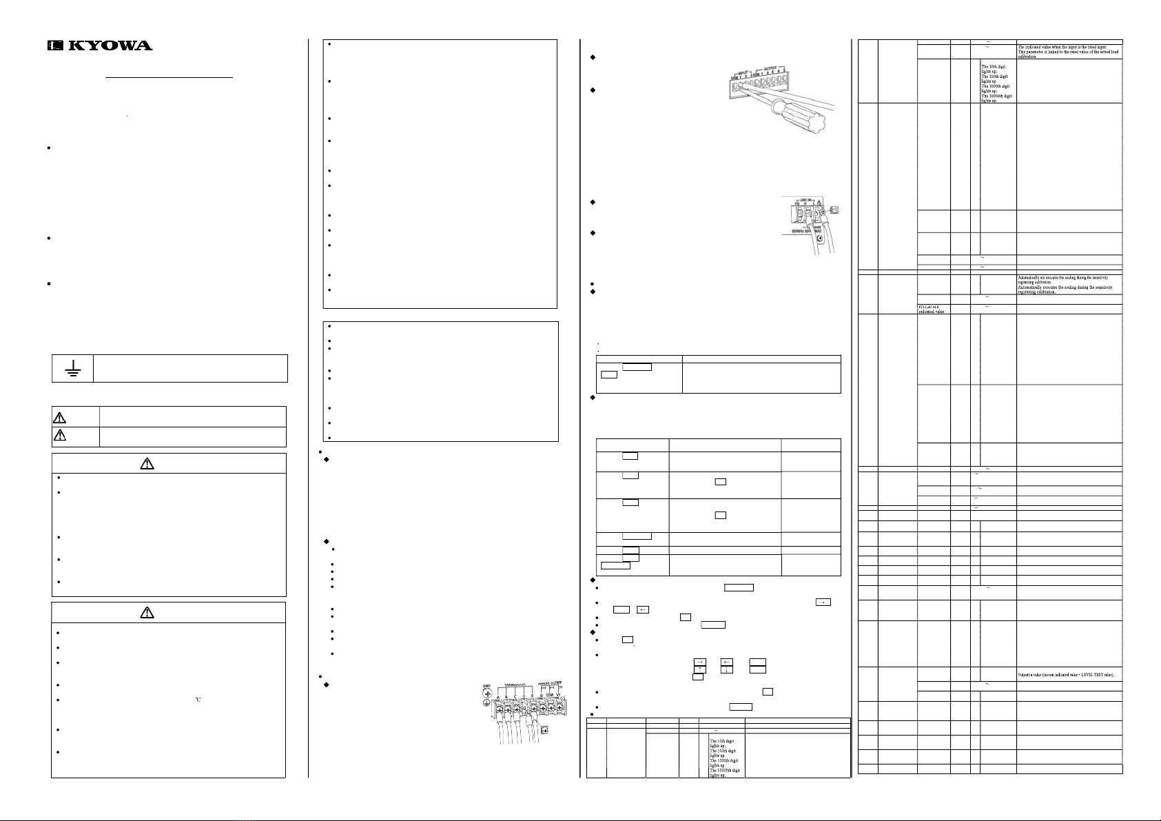
CONNECTION
TO CONNECT TRANSDUCERS
Connect transducers to terminals Ato E as described in the following.
(Cable colors are KYOWA's standard color codes.)
A: Bridge excitation (+) Red cable
B: Bridge output (-) White cable
C: Bridge excitation (-) Black cable
D: Bridge output (+) Green cable
E: Shield
TO CONNECT [INPUT] TERMINALS
COM : Common
1 : ZERO command
2 : HOLD command
3 : RESET command
TO CONNECT [OUTPUT] TERMINALS
COM : Common
1 : [HH] output (comparator-3 output)
2 : [HI] output (comparator-1 output)
3 : [OK] output
4 : [LO] output (comparator-2 output)
5 : [LL] output (comparator-4 output)
Connect cables as follows.
1) Strip off the coating of the wire for approx. 11 mm and twist the tip of the wire for not to loosen.
The available wire ranges are as follows.
2) Press the lower button strongly by using the accessory flat-head screw driver as described in the
upper figure.
3) Carefully insert the twisted wires into the upper hole.
4) Remove the flat-head screw driver from the lower button. And pull the wires gently to check
if they are securely inserted.
TO CONNECT [ANALOG OUTPUT] TERMINALS
COM : Common
Vo : Voltage output terminal (±10 V)
Io : Current output terminal (4 to 20 mA)
TO CONNECT POWER SUPPLY
Do not forget to check that power voltage. Be sure to use the cable with
rated voltage having more than power supply voltage.
WGA-680A-00~04 (AC models):AC100~240V, Power consumption: 20VA or less
WGA-680A-10~14 (DC models):DC10~30V, Power consumption: 10W or less *Figure is AC model
KEY OPERATIONS
Lock function
The LOCK function is used to prohibit the change in pre-set values in order to prevent erroneous
operation.
In the [LOCK] status, you are not able to change the function and limit values
([HI] limit value, [LO] limit value, etc.).
However, you are able to monitor the pre-set comparator limit values.
Before changing functions and limit values, cancel the [LOCK] status.
Power ON the WGA-680A and the mode is the MEASURING mode in the [LOCK] status.
After changing the settings, make the WGA-680A to the [LOCK] status to prevent erroneous operation.
Key operation Operations
Press the FUNCTION key + the
HOLD key for 2 seconds at the
same time.
In [LOCK] status :
[LOCK] status is canceled. [LOCK] LED turns ON.
In NOT [LOCK] status :
The status becomes [LOCK] status. [LOCK] LED turns OFF.
Key operations in MEASURING mode
During the MEASURING mode, the WGA-680Ameasures physical quantities (load, pressure, torque,
displacement, etc.) by using strain gage transducers and displays their values.
To go to the SETTING mode, FUNCTION SELECTING mode, and LOCK mode, press keys in the
MEASURING mode.
However, the [LOCK] status limits the key operations. For details, see the following table.
Key operation Operations when the [LOCK] LED is OFF. Operations when the
[LOCK] LED is ON.
Press the ZERO key
for 2 seconds.
Executes the DIGITAL ZERO function, "0"
is displayed as the indicated value, and goes
to the MEASURING mode.
Executes no function.
Press the HI HH key
for 2 seconds.
Goes to the [HI] limit value SETTING mode.
After pressing the SET key to set the [HI]
limit value, the SETTING mode goes to the
[HH] limit value SETTING mode.
Pre-set values is
displayed.
Press the LO LL key
for 2 seconds.
Goes to the [LO] limit value SETTING
mode.
After pressing the SET key to set the [LO]
limit value, the SETTING mode goes to the
[LL] limit value SETTING mode.
Pre-set values is
displayed.
Press the FUNCTION key
for 2 seconds.
Goes to the FUNCTION SELECTING mode. Executes no function.
Press the HOLD key. Operates in the pre-set HOLD mode. Executes no function.
Press the HOLD key + the
FUNCTION key for 2
seconds at the same time.
The [LOCK] LED lights up and the mode
goes to the MEASURING mode.
The [LOCK] LED
lights off. You are
able to select modes.
Key operations in FUNCTION SELECTING mode
To go to the FUNCTION SELECTING mode, press the FUNCTION key for 2 seconds in the
MEASURING mode. The "F-01" is displayed on the indicator and you are able to select functions.
To select the functions from "F-01" to "F-26" on the FUNCTION SELECTING mode, press the
key or SHIFT + key.
To determine the function, press the SET key. The mode goes to the SETTING mode.
To back to the MEASURING mode, press the CANCEL key on the FUNCTION SELECTING mode.
Key operations in SETTING mode
Press the SET key after selecting the function on the FUNCTION SELECTING mode, the mode goes
to the function s SETTING mode.
To set numerical values.
Move digits : Press the key, key + SHIFT key.
Change numerical values : Press the key, key + SHIFT key.
Register pre-set values : Press the SET key. The changed value is determined and stored
(registered) in the internal memory.
When numeric values are not required to set, "...." is displayed. Press the SET key in this status, the
function is executed.
To back to the FUNCTION SELECTING mode, press the CANCEL key on the SETTING mode.
Table of functions
o. Functions Parameters
Digits
O
tions/ran
es Remarks
F-01 Ori
inal value The current in
ut value
mV/V
is dis
la
ed.
F-02 Actual load
calibration
Rated value -99999 +99999 Linked to the sensitivit
re
isterin
calibration.
Decimal point
position
10e0
one Decimal
oint: None
10e1 The decimal point is displayed at the 10th digit.
10e2 The decimal point is displayed at the 100th digit.
10e3 The decimal point is displayed at the 1000th digit.
10e4 The decimal point is displayed at the 10000th digit.
F-03 Sensitivity
registering
calibration
Rated out
ut -3.2000 +3.2000 Rated in
ut
mV/V
Rated value -99999 +99999
Decimal point
position
10e0
one Decimal
oint: None
10e1 The decimal point is displayed at the 10th digit.
10e2 The decimal point is displayed at the 100th digit.
10e3 The decimal point is displayed at the 1000th digit.
10e4 The decimal point is displayed at the 10000th digit.
F-04 Hold mode Hold mode 10e2 0 Tracking
ormal measurements
1 Arbitrary point
hold
Sample hold
2 Peak Hold(PH) Peak Hold
3 Interval-specified
PH
Interval-specified peak hold
4 Time-specified
PH
Time-specified peak hold
5 Bottom hold(BH) Bottom hold
6 Interval
-specified BH
Interval -specified bottom hold
7 Time-specified
BH
Time-specified bottom hold
8 Peak-to-peak
hold (p-p)
Pea
-to-
eak hold
9 Interval
-specified P-P
Interval-specified peak-to-
eak hold
A Time-specified
P-P
Time-specified pea
-to-
eak hold
Display mode 10e1 0 Normal display
mode
ormal display mode
(Interval-specified and time-specified only.)
1 Hold display
mode
Hold display mode
(Interval-specified and time-specified only.)
Comparison
mode
10e0 0 Normal
comparison mode
ormal comparison mode
(Compares data normally.)
1 Hold comparison
mode
Hold comparison mode
(Compares data during the holding operations.)
Delay time 0.00 9.99 The time to starting the detection interval from being
turned on HOLD command.
Detec
time 0.01 9.99 S
ecified-time PH/BH/P-P Onl
.
F-05 Sel
-check Sel
-check function
EEPROM and RAM
F-06 Analog output
(D/A) scaling
Automatic
scaling
10e0 0 Manual
1 Auto
ZERO indicated
value
-99999 +99999 Indicated value that outputs 0V.
-99999 +99999 Indicated value that outputs 10V.
F-07 Smoothing The number of
moving average
times
10e2 0 0 times
one
1 2 times 2 times (0.5msec)
2 4 times 4 times (1msec)
3 8 times 8 times (2msec)
4 16 times 16 times (4msec)
5 32 times 32 times (8msec)
6 64 times 64 times (16msec)
7 128 times 128 times (32msec)
8 256 times 256 times (64msec)
9 512 times 512 times (128msec)
A 1024 times 1024 ti
es (256msec)
2048 times 2048 times (512msec)
Minimum scale 10e1 0 1 1 counts.
1 2 2 counts.
2 5 5 counts.
3 10 10 counts.
4 20 20 counts.
5 50 50 counts.
6 100 100 counts.
7 200 200 counts.
8 500 500 counts.
9 1000 1000 counts.
Analog filter 10e0 0 300Hz Cutoff frequency : 300Hz
1 100Hz Cutoff frequency : 100Hz
2 30Hz Cutoff frequency : 30Hz
3 10Hz Cutoff frequency : 10Hz
F-08 Additional value -99999 +99999 Dis
la
offset
F-09 Automatic
ZERO
compensation
ZERO
compensation
ran
e
0 99999 The range of the Automatic ZERO compensation.
Determination
time
0.0 9.9 The determination time of the Automatic ZERO
com
ensation.
Zero-nea
-zero 0 9 The compensation range t hat automatically changes
the least si
nificant di
it number to zero.
F-10 H
steresis 0 99999 Common h
steresis
F-11 BCD output Logic For details, see the "INSTRUCTION MANUAL (FOR
BCD/RS-232C/RS-485/TEDS OPTIONS)".
F-12 Initialize Initialize 10e0 0 OFF
ot initialized
1 ON Initialized (excluding the BV and calibration value)
F-13 BV
selection
Bridge
excitation
volta
e
10e0 0 10V Brid
e excitation volta
e: 10 V
1 2V Bridge excitation voltage : 2 V
F-14 TEDS reading ite
For details, see the "INSTRUCTION MANUAL (FOR
BCD/RS-232C/RS-485/TEDS OPTIONS
".
F-16 RS communication
settin
s
For details, see the "INSTRUCTION MANUAL (FO R
BCD/RS-232C/RS-485/TEDS OPTIONS
".
F-17 Device ID For details, see the "INSTRUCTION MANUAL (FOR
BCD/RS-232C/RS-485/TEDS OPTIONS
".
F-18 CC-Link For details, see the "INSTRUCTION MANUAL (FOR
CC-LINK OPTION)".
F-19
umeric value
registering
calibration
Zero-
oint
output value
-3.2000 +3.2000 The ZERO indicated value that is registered at
calibration.
F-20 Operation patter
Operation
pattern
10e0 0 Pattern 0 Selects the pattern of comparator values from
registered 4 patterns.
1 Patter
1
2 Patter
2
3 Patter
3
F-21 Updating rate of
displaying values
Updating rate 10e0 0 15.60 times/sec Thinning: 1/256 time, 64msec
1 7.80 times/sec Thinning: 1/512 time, 128msec
2 3.90 times/sec Thinning: 1/1024 time, 256msec
3 1.95 times/sec Thinning: 1/2048 time, 512msec
4 0.98 times/sec Thinning: 1/4096 time, 1024msec
5 0.49 times/sec Thinning: 1/8192 time, 2048msec
6 0.24 times/sec Thinning: 1/16384 time, 4096msec
7 0.12 times/sec Thinning: 1/32768 time, 8192msec
F-22 Level Test
Signals
Displa
additional
function
10e0 0 Disabled Out
uts the LEVEL TEST values onl
.
1 Enable
Level Test
values
-99999 +99999
Level Test
ON/OFF
10e0 0 OFF Turns OFF the LEVEL TEST values.
1 ON Turns ON the LEV EL TEST values.
F-23 [HH]
comparator
(comparator-3)
functions
"High limit" or
"Low limit"
10e0 0 Hi
h limit Assign "0: High limit" or "1: Low limit" of the [HH]
comparator (comparator-3).
1 Low limit
F-24 [HI] comparator
(comparator-1)
functions
"High limit" or
"Low limit"
10e0 0 Hi
h limit Assign "0: High limit" or "1: Low limit" of the [HI]
comparator (comparator-1).
1 Low limit
F-25 [LO] comparator
(comparator-2)
functions
"High limit" or
"Low limit"
10e0 0 Hi
h limit Assign "0: High limit" or "1: Low limit" of the [LO]
comparator (comparator-2).
1 Low limit
F-26 [LL] comparator
(comparator-4)
functions
"High limit" or
"Low limit"
10e0 0 Hi
h limit Assign "0: High limit" or "1: Low limit" of the [LL]
comparator (comparator-4).
1 Low limit
F-27 Display stability Disabl/E
ab; 10e0 0
1
Disable
Enable


