manuals.online logo
Brands
  1. Home
  2. •
  3. Brands
  4. •
  5. KYOWA
  6. •
  7. Amplifier
  8. •
  9. KYOWA WGA-680A Series User manual

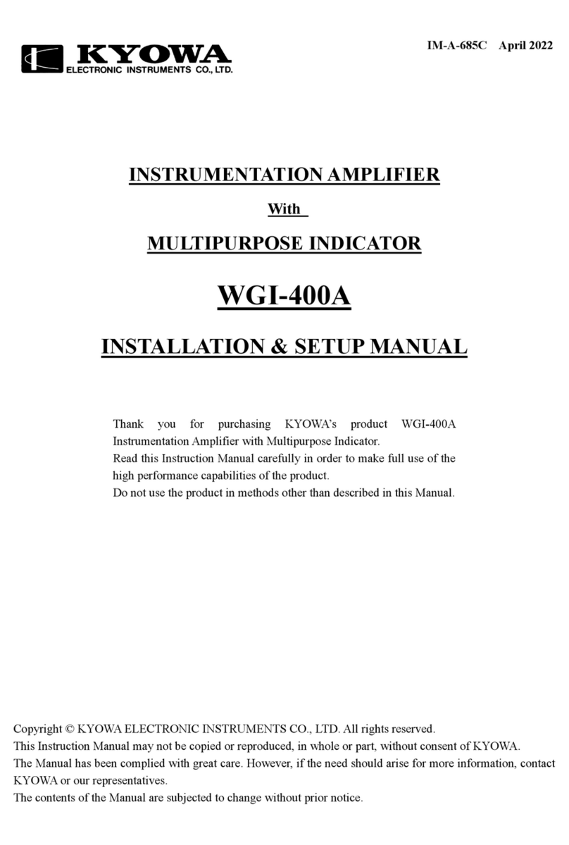
KYOWA WGA-680A Series User manual

IM-A-1062H September 2022
INSTRUCTION MANUAL
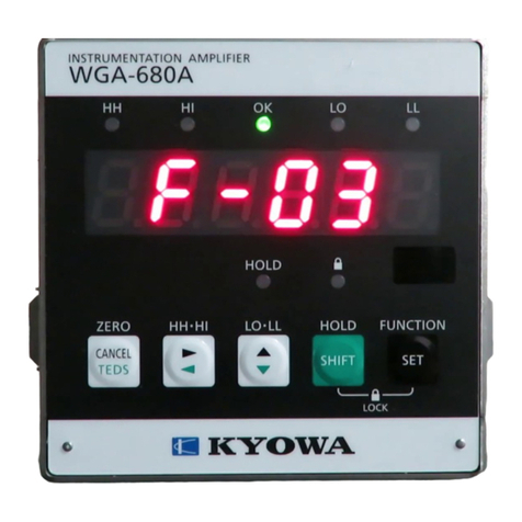
WGA-680A
INSTRUMENTATION AMPLIFIER
(FOR CC-Link OPTIONS)
ACmodel
WGA-680A-04: CC-Link
DCmodel
WGA-680A-14: CC-Link
Thank you for purchasing KYOWA’s product WGA-680A Instrumentation
Amplifier.
Read this Instruction Manual carefully in order to make full use of the high
performance capabilities of the product.
Do not use the product in methods other than described in this Manual.
Generally, company names and trade names described in this Instruction Manual are trademarks or registered
trademarks of the companies.
This Instruction Manual may not be copied or reproduced, in whole or part, without consent of KYOWA.
Copyright © Kyowa Electronic Instruments Co., Ltd. All rights reserved.
The contents of the Instruction Manual are subjected to change without prior notice.
We assume no responsibility whatever for any damage resulting from the use of this product.
1
CONTENTS
STANDARD ACCESSORIES ꞏꞏꞏꞏꞏꞏꞏꞏꞏꞏꞏꞏꞏꞏꞏꞏꞏꞏꞏꞏꞏꞏꞏꞏꞏꞏꞏꞏꞏꞏꞏꞏꞏꞏꞏꞏꞏꞏꞏꞏꞏꞏꞏꞏꞏꞏꞏꞏꞏꞏꞏꞏꞏꞏꞏꞏꞏꞏꞏꞏꞏꞏꞏꞏꞏꞏꞏꞏꞏꞏꞏꞏꞏꞏꞏꞏꞏꞏꞏꞏꞏꞏꞏꞏꞏꞏꞏꞏꞏꞏꞏꞏꞏꞏꞏꞏꞏꞏꞏꞏꞏꞏꞏꞏꞏꞏꞏꞏ 2
OPTIONAL ACCESSORIES ꞏꞏꞏꞏꞏꞏꞏꞏꞏꞏꞏꞏꞏꞏꞏꞏꞏꞏꞏꞏꞏꞏꞏꞏꞏꞏꞏꞏꞏꞏꞏꞏꞏꞏꞏꞏꞏꞏꞏꞏꞏꞏꞏꞏꞏꞏꞏꞏꞏꞏꞏꞏꞏꞏꞏꞏꞏꞏꞏꞏꞏꞏꞏꞏꞏꞏꞏꞏꞏꞏꞏꞏꞏꞏꞏꞏꞏꞏꞏꞏꞏꞏꞏꞏꞏꞏꞏꞏꞏꞏꞏꞏꞏꞏꞏꞏꞏꞏꞏꞏꞏꞏꞏꞏꞏꞏꞏꞏꞏ 2
SAFETY PRECAUTIONS (Do not forget to read the safety precautions prior to use.) ꞏꞏꞏꞏꞏꞏꞏꞏꞏꞏꞏꞏꞏꞏꞏꞏꞏꞏꞏꞏꞏꞏꞏꞏꞏꞏꞏꞏꞏꞏꞏꞏꞏꞏꞏꞏꞏꞏꞏꞏꞏꞏ 3
LIMITED LIFE PARTS AND PREVENTIVE MAINTENANCEꞏꞏꞏꞏꞏꞏꞏꞏꞏꞏꞏꞏꞏꞏꞏꞏꞏꞏꞏꞏꞏꞏꞏꞏꞏꞏꞏꞏꞏꞏꞏꞏꞏꞏꞏꞏꞏꞏꞏꞏꞏꞏꞏꞏꞏꞏꞏꞏꞏꞏꞏꞏꞏꞏꞏꞏꞏꞏꞏꞏꞏꞏꞏꞏꞏꞏꞏ 5
WGA-680A REPLACEMENT BEFORE THE END OF SERVICE LIFE ꞏꞏꞏꞏꞏꞏꞏꞏꞏꞏꞏꞏꞏꞏꞏꞏꞏꞏꞏꞏꞏꞏꞏꞏꞏꞏꞏꞏꞏꞏꞏꞏꞏꞏꞏꞏꞏꞏꞏꞏꞏꞏꞏꞏꞏꞏꞏꞏꞏꞏꞏꞏꞏꞏꞏꞏꞏ 5
NOTATIONS USED IN THE INSTRUCTION MANUAL ꞏꞏꞏꞏꞏꞏꞏꞏꞏꞏꞏꞏꞏꞏꞏꞏꞏꞏꞏꞏꞏꞏꞏꞏꞏꞏꞏꞏꞏꞏꞏꞏꞏꞏꞏꞏꞏꞏꞏꞏꞏꞏꞏꞏꞏꞏꞏꞏꞏꞏꞏꞏꞏꞏꞏꞏꞏꞏꞏꞏꞏꞏꞏꞏꞏꞏꞏꞏꞏꞏꞏꞏꞏꞏ 5
PRECAUTIONS ON CE MARKING ꞏꞏꞏꞏꞏꞏꞏꞏꞏꞏꞏꞏꞏꞏꞏꞏꞏꞏꞏꞏꞏꞏꞏꞏꞏꞏꞏꞏꞏꞏꞏꞏꞏꞏꞏꞏꞏꞏꞏꞏꞏꞏꞏꞏꞏꞏꞏꞏꞏꞏꞏꞏꞏꞏꞏꞏꞏꞏꞏꞏꞏꞏꞏꞏꞏꞏꞏꞏꞏꞏꞏꞏꞏꞏꞏꞏꞏꞏꞏꞏꞏꞏꞏꞏꞏꞏꞏꞏꞏꞏꞏꞏꞏꞏꞏꞏꞏꞏꞏ 6
1. OUTLINE OF PRODUCTꞏꞏꞏꞏꞏꞏꞏꞏꞏꞏꞏꞏꞏꞏꞏꞏꞏꞏꞏꞏꞏꞏꞏꞏꞏꞏꞏꞏꞏꞏꞏꞏꞏꞏꞏꞏꞏꞏꞏꞏꞏꞏꞏꞏꞏꞏꞏꞏꞏꞏꞏꞏꞏꞏꞏꞏꞏꞏꞏꞏꞏꞏꞏꞏꞏꞏꞏꞏꞏꞏꞏꞏꞏꞏꞏꞏꞏꞏꞏꞏꞏꞏꞏꞏꞏꞏꞏꞏꞏꞏꞏꞏꞏꞏꞏꞏꞏꞏꞏꞏꞏꞏꞏꞏꞏꞏꞏꞏꞏꞏ 7
2. CONTROLS AND INDICATORS (REAR PANEL) ꞏꞏꞏꞏꞏꞏꞏꞏꞏꞏꞏꞏꞏꞏꞏꞏꞏꞏꞏꞏꞏꞏꞏꞏꞏꞏꞏꞏꞏꞏꞏꞏꞏꞏꞏꞏꞏꞏꞏꞏꞏꞏꞏꞏꞏꞏꞏꞏꞏꞏꞏꞏꞏꞏꞏꞏꞏꞏꞏꞏꞏꞏꞏꞏꞏꞏꞏꞏꞏꞏꞏꞏꞏꞏꞏꞏꞏꞏꞏ 7
3. CC-Link SPECIFICATIONS ꞏꞏꞏꞏꞏꞏꞏꞏꞏꞏꞏꞏꞏꞏꞏꞏꞏꞏꞏꞏꞏꞏꞏꞏꞏꞏꞏꞏꞏꞏꞏꞏꞏꞏꞏꞏꞏꞏꞏꞏꞏꞏꞏꞏꞏꞏꞏꞏꞏꞏꞏꞏꞏꞏꞏꞏꞏꞏꞏꞏꞏꞏꞏꞏꞏꞏꞏꞏꞏꞏꞏꞏꞏꞏꞏꞏꞏꞏꞏꞏꞏꞏꞏꞏꞏꞏꞏꞏꞏꞏꞏꞏꞏꞏꞏꞏꞏꞏꞏꞏꞏꞏꞏꞏꞏꞏꞏ 7
4. COMMUNICATION CONNECTORS ꞏꞏꞏꞏꞏꞏꞏꞏꞏꞏꞏꞏꞏꞏꞏꞏꞏꞏꞏꞏꞏꞏꞏꞏꞏꞏꞏꞏꞏꞏꞏꞏꞏꞏꞏꞏꞏꞏꞏꞏꞏꞏꞏꞏꞏꞏꞏꞏꞏꞏꞏꞏꞏꞏꞏꞏꞏꞏꞏꞏꞏꞏꞏꞏꞏꞏꞏꞏꞏꞏꞏꞏꞏꞏꞏꞏꞏꞏꞏꞏꞏꞏꞏꞏꞏꞏꞏꞏꞏꞏꞏꞏꞏꞏꞏ 7
5. STATUS LEDꞏꞏꞏꞏꞏꞏꞏꞏꞏꞏꞏꞏꞏꞏꞏꞏꞏꞏꞏꞏꞏꞏꞏꞏꞏꞏꞏꞏꞏꞏꞏꞏꞏꞏꞏꞏꞏꞏꞏꞏꞏꞏꞏꞏꞏꞏꞏꞏꞏꞏꞏꞏꞏꞏꞏꞏꞏꞏꞏꞏꞏꞏꞏꞏꞏꞏꞏꞏꞏꞏꞏꞏꞏꞏꞏꞏꞏꞏꞏꞏꞏꞏꞏꞏꞏꞏꞏꞏꞏꞏꞏꞏꞏꞏꞏꞏꞏꞏꞏꞏꞏꞏꞏꞏꞏꞏꞏꞏꞏꞏꞏꞏꞏꞏꞏꞏꞏꞏꞏꞏꞏꞏꞏꞏꞏ 8
6. CC-Link SETTINGS ꞏꞏꞏꞏꞏꞏꞏꞏꞏꞏꞏꞏꞏꞏꞏꞏꞏꞏꞏꞏꞏꞏꞏꞏꞏꞏꞏꞏꞏꞏꞏꞏꞏꞏꞏꞏꞏꞏꞏꞏꞏꞏꞏꞏꞏꞏꞏꞏꞏꞏꞏꞏꞏꞏꞏꞏꞏꞏꞏꞏꞏꞏꞏꞏꞏꞏꞏꞏꞏꞏꞏꞏꞏꞏꞏꞏꞏꞏꞏꞏꞏꞏꞏꞏꞏꞏꞏꞏꞏꞏꞏꞏꞏꞏꞏꞏꞏꞏꞏꞏꞏꞏꞏꞏꞏꞏꞏꞏꞏꞏꞏꞏꞏꞏꞏꞏ 9
7. BUFFER ADDRESS OF PLC ꞏꞏꞏꞏꞏꞏꞏꞏꞏꞏꞏꞏꞏꞏꞏꞏꞏꞏꞏꞏꞏꞏꞏꞏꞏꞏꞏꞏꞏꞏꞏꞏꞏꞏꞏꞏꞏꞏꞏꞏꞏꞏꞏꞏꞏꞏꞏꞏꞏꞏꞏꞏꞏꞏꞏꞏꞏꞏꞏꞏꞏꞏꞏꞏꞏꞏꞏꞏꞏꞏꞏꞏꞏꞏꞏꞏꞏꞏꞏꞏꞏꞏꞏꞏꞏꞏꞏꞏꞏꞏꞏꞏꞏꞏꞏꞏꞏꞏꞏꞏꞏꞏꞏꞏꞏ 9
8. ADDRESS MAP ꞏꞏꞏꞏꞏꞏꞏꞏꞏꞏꞏꞏꞏꞏꞏꞏꞏꞏꞏꞏꞏꞏꞏꞏꞏꞏꞏꞏꞏꞏꞏꞏꞏꞏꞏꞏꞏꞏꞏꞏꞏꞏꞏꞏꞏꞏꞏꞏꞏꞏꞏꞏꞏꞏꞏꞏꞏꞏꞏꞏꞏꞏꞏꞏꞏꞏꞏꞏꞏꞏꞏꞏꞏꞏꞏꞏꞏꞏꞏꞏꞏꞏꞏꞏꞏꞏꞏꞏꞏꞏꞏꞏꞏꞏꞏꞏꞏꞏꞏꞏꞏꞏꞏꞏꞏꞏꞏꞏꞏꞏꞏꞏꞏꞏꞏꞏꞏꞏꞏꞏ10
8-1. REMOTE REGISTER: M →R ꞏꞏꞏꞏꞏꞏꞏꞏꞏꞏꞏꞏꞏꞏꞏꞏꞏꞏꞏꞏꞏꞏꞏꞏꞏꞏꞏꞏꞏꞏꞏꞏꞏꞏꞏꞏꞏꞏꞏꞏꞏꞏꞏꞏꞏꞏꞏꞏꞏꞏꞏꞏꞏꞏꞏꞏꞏꞏꞏꞏꞏꞏꞏꞏꞏꞏꞏꞏꞏꞏꞏꞏꞏꞏꞏꞏꞏꞏꞏꞏꞏꞏꞏꞏꞏꞏꞏꞏꞏꞏꞏꞏꞏꞏꞏꞏꞏ10
8-1-1. Address map of the remote register M →Rꞏꞏꞏꞏꞏꞏꞏꞏꞏꞏꞏꞏꞏꞏꞏꞏꞏꞏꞏꞏꞏꞏꞏꞏꞏꞏꞏꞏꞏꞏꞏꞏꞏꞏꞏꞏꞏꞏꞏꞏꞏꞏꞏꞏꞏꞏꞏꞏꞏꞏꞏꞏꞏꞏꞏꞏꞏꞏꞏꞏꞏꞏꞏꞏꞏꞏꞏꞏꞏꞏꞏꞏꞏꞏꞏꞏꞏꞏ10
8-1-2. Format of the remote register M →Rꞏꞏꞏꞏꞏꞏꞏꞏꞏꞏꞏꞏꞏꞏꞏꞏꞏꞏꞏꞏꞏꞏꞏꞏꞏꞏꞏꞏꞏꞏꞏꞏꞏꞏꞏꞏꞏꞏꞏꞏꞏꞏꞏꞏꞏꞏꞏꞏꞏꞏꞏꞏꞏꞏꞏꞏꞏꞏꞏꞏꞏꞏꞏꞏꞏꞏꞏꞏꞏꞏꞏꞏꞏꞏꞏꞏꞏꞏꞏꞏꞏꞏꞏꞏꞏ 11
8-2. REMOTE REGISTER: R →M ꞏꞏꞏꞏꞏꞏꞏꞏꞏꞏꞏꞏꞏꞏꞏꞏꞏꞏꞏꞏꞏꞏꞏꞏꞏꞏꞏꞏꞏꞏꞏꞏꞏꞏꞏꞏꞏꞏꞏꞏꞏꞏꞏꞏꞏꞏꞏꞏꞏꞏꞏꞏꞏꞏꞏꞏꞏꞏꞏꞏꞏꞏꞏꞏꞏꞏꞏꞏꞏꞏꞏꞏꞏꞏꞏꞏꞏꞏꞏꞏꞏꞏꞏꞏꞏꞏꞏꞏꞏꞏꞏꞏꞏꞏꞏꞏꞏ12
8-2-1. Address map of the remote register R →Mꞏꞏꞏꞏꞏꞏꞏꞏꞏꞏꞏꞏꞏꞏꞏꞏꞏꞏꞏꞏꞏꞏꞏꞏꞏꞏꞏꞏꞏꞏꞏꞏꞏꞏꞏꞏꞏꞏꞏꞏꞏꞏꞏꞏꞏꞏꞏꞏꞏꞏꞏꞏꞏꞏꞏꞏꞏꞏꞏꞏꞏꞏꞏꞏꞏꞏꞏꞏꞏꞏꞏꞏꞏꞏꞏꞏꞏꞏ12
8-2-2. Format of the remote register R →Mꞏꞏꞏꞏꞏꞏꞏꞏꞏꞏꞏꞏꞏꞏꞏꞏꞏꞏꞏꞏꞏꞏꞏꞏꞏꞏꞏꞏꞏꞏꞏꞏꞏꞏꞏꞏꞏꞏꞏꞏꞏꞏꞏꞏꞏꞏꞏꞏꞏꞏꞏꞏꞏꞏꞏꞏꞏꞏꞏꞏꞏꞏꞏꞏꞏꞏꞏꞏꞏꞏꞏꞏꞏꞏꞏꞏꞏꞏꞏꞏꞏꞏꞏꞏꞏ13
8-3. REMOTE INPUT AND REMOTE OUTPUTꞏꞏꞏꞏꞏꞏꞏꞏꞏꞏꞏꞏꞏꞏꞏꞏꞏꞏꞏꞏꞏꞏꞏꞏꞏꞏꞏꞏꞏꞏꞏꞏꞏꞏꞏꞏꞏꞏꞏꞏꞏꞏꞏꞏꞏꞏꞏꞏꞏꞏꞏꞏꞏꞏꞏꞏꞏꞏꞏꞏꞏꞏꞏꞏꞏꞏꞏꞏꞏꞏꞏꞏꞏꞏꞏꞏꞏꞏꞏꞏꞏ15
8-3-1. Address map ꞏꞏꞏꞏꞏꞏꞏꞏꞏꞏꞏꞏꞏꞏꞏꞏꞏꞏꞏꞏꞏꞏꞏꞏꞏꞏꞏꞏꞏꞏꞏꞏꞏꞏꞏꞏꞏꞏꞏꞏꞏꞏꞏꞏꞏꞏꞏꞏꞏꞏꞏꞏꞏꞏꞏꞏꞏꞏꞏꞏꞏꞏꞏꞏꞏꞏꞏꞏꞏꞏꞏꞏꞏꞏꞏꞏꞏꞏꞏꞏꞏꞏꞏꞏꞏꞏꞏꞏꞏꞏꞏꞏꞏꞏꞏꞏꞏꞏꞏꞏꞏꞏꞏꞏꞏꞏꞏꞏꞏꞏꞏꞏꞏꞏ15
8-3-2. Contents of the remote output RY (M →R) ꞏꞏꞏꞏꞏꞏꞏꞏꞏꞏꞏꞏꞏꞏꞏꞏꞏꞏꞏꞏꞏꞏꞏꞏꞏꞏꞏꞏꞏꞏꞏꞏꞏꞏꞏꞏꞏꞏꞏꞏꞏꞏꞏꞏꞏꞏꞏꞏꞏꞏꞏꞏꞏꞏꞏꞏꞏꞏꞏꞏꞏꞏꞏꞏꞏꞏꞏꞏꞏꞏꞏꞏꞏꞏꞏꞏꞏ19
8-3-3. Contents of the remote input RX (R →M)ꞏꞏꞏꞏꞏꞏꞏꞏꞏꞏꞏꞏꞏꞏꞏꞏꞏꞏꞏꞏꞏꞏꞏꞏꞏꞏꞏꞏꞏꞏꞏꞏꞏꞏꞏꞏꞏꞏꞏꞏꞏꞏꞏꞏꞏꞏꞏꞏꞏꞏꞏꞏꞏꞏꞏꞏꞏꞏꞏꞏꞏꞏꞏꞏꞏꞏꞏꞏꞏꞏꞏꞏꞏꞏꞏꞏꞏꞏꞏ20
9. LIST OF COMMANDSꞏꞏꞏꞏꞏꞏꞏꞏꞏꞏꞏꞏꞏꞏꞏꞏꞏꞏꞏꞏꞏꞏꞏꞏꞏꞏꞏꞏꞏꞏꞏꞏꞏꞏꞏꞏꞏꞏꞏꞏꞏꞏꞏꞏꞏꞏꞏꞏꞏꞏꞏꞏꞏꞏꞏꞏꞏꞏꞏꞏꞏꞏꞏꞏꞏꞏꞏꞏꞏꞏꞏꞏꞏꞏꞏꞏꞏꞏꞏꞏꞏꞏꞏꞏꞏꞏꞏꞏꞏꞏꞏꞏꞏꞏꞏꞏꞏꞏꞏꞏꞏꞏꞏꞏꞏꞏꞏꞏꞏꞏꞏꞏ21
9-1. COMMANDS FOR THE OPERATION PATTERN ꞏꞏꞏꞏꞏꞏꞏꞏꞏꞏꞏꞏꞏꞏꞏꞏꞏꞏꞏꞏꞏꞏꞏꞏꞏꞏꞏꞏꞏꞏꞏꞏꞏꞏꞏꞏꞏꞏꞏꞏꞏꞏꞏꞏꞏꞏꞏꞏꞏꞏꞏꞏꞏꞏꞏꞏꞏꞏꞏꞏꞏꞏꞏꞏꞏꞏꞏꞏꞏꞏꞏꞏꞏ21
9-2. COMMANDS FOR THE GENERAL SETTINGSꞏꞏꞏꞏꞏꞏꞏꞏꞏꞏꞏꞏꞏꞏꞏꞏꞏꞏꞏꞏꞏꞏꞏꞏꞏꞏꞏꞏꞏꞏꞏꞏꞏꞏꞏꞏꞏꞏꞏꞏꞏꞏꞏꞏꞏꞏꞏꞏꞏꞏꞏꞏꞏꞏꞏꞏꞏꞏꞏꞏꞏꞏꞏꞏꞏꞏꞏꞏꞏꞏꞏꞏꞏꞏꞏ21
9-3. COMMANDS FOR THE CONTROL INPUT SIGNALSꞏꞏꞏꞏꞏꞏꞏꞏꞏꞏꞏꞏꞏꞏꞏꞏꞏꞏꞏꞏꞏꞏꞏꞏꞏꞏꞏꞏꞏꞏꞏꞏꞏꞏꞏꞏꞏꞏꞏꞏꞏꞏꞏꞏꞏꞏꞏꞏꞏꞏꞏꞏꞏꞏꞏꞏꞏꞏꞏꞏꞏꞏꞏꞏꞏꞏꞏ22
9-4. ERROR CODESꞏꞏꞏꞏꞏꞏꞏꞏꞏꞏꞏꞏꞏꞏꞏꞏꞏꞏꞏꞏꞏꞏꞏꞏꞏꞏꞏꞏꞏꞏꞏꞏꞏꞏꞏꞏꞏꞏꞏꞏꞏꞏꞏꞏꞏꞏꞏꞏꞏꞏꞏꞏꞏꞏꞏꞏꞏꞏꞏꞏꞏꞏꞏꞏꞏꞏꞏꞏꞏꞏꞏꞏꞏꞏꞏꞏꞏꞏꞏꞏꞏꞏꞏꞏꞏꞏꞏꞏꞏꞏꞏꞏꞏꞏꞏꞏꞏꞏꞏꞏꞏꞏꞏꞏꞏꞏꞏꞏꞏꞏꞏꞏꞏꞏꞏ22
10. SETTING PROCEDURESꞏꞏꞏꞏꞏꞏꞏꞏꞏꞏꞏꞏꞏꞏꞏꞏꞏꞏꞏꞏꞏꞏꞏꞏꞏꞏꞏꞏꞏꞏꞏꞏꞏꞏꞏꞏꞏꞏꞏꞏꞏꞏꞏꞏꞏꞏꞏꞏꞏꞏꞏꞏꞏꞏꞏꞏꞏꞏꞏꞏꞏꞏꞏꞏꞏꞏꞏꞏꞏꞏꞏꞏꞏꞏꞏꞏꞏꞏꞏꞏꞏꞏꞏꞏꞏꞏꞏꞏꞏꞏꞏꞏꞏꞏꞏꞏꞏꞏꞏꞏꞏꞏꞏꞏꞏꞏꞏ23
10-1. TO WRITE THE PRE-SET VALUES OF THE OPERATION PATTERN LIMITED DATA (BY USING TRE
REQUEST 1) ꞏꞏꞏꞏꞏꞏꞏꞏꞏꞏꞏꞏꞏꞏꞏꞏꞏꞏꞏꞏꞏꞏꞏꞏꞏꞏꞏꞏꞏꞏꞏꞏꞏꞏꞏꞏꞏꞏꞏꞏꞏꞏꞏꞏꞏꞏꞏꞏꞏꞏꞏꞏꞏꞏꞏꞏꞏꞏꞏꞏꞏꞏꞏꞏꞏꞏꞏꞏꞏꞏꞏꞏꞏꞏꞏꞏꞏꞏꞏꞏꞏꞏꞏꞏꞏꞏꞏꞏꞏꞏꞏꞏꞏꞏꞏꞏꞏꞏꞏꞏꞏꞏꞏꞏꞏꞏꞏꞏꞏꞏꞏꞏꞏꞏꞏꞏꞏꞏ23
10-2. TO WRITE THE PRE-SET VALUES OF THE COMMANDS (BY USING THE REQUEST 2) ꞏꞏꞏꞏꞏꞏꞏꞏꞏꞏꞏꞏꞏꞏꞏꞏꞏꞏꞏ24
10-3. TO READ THE PRE-SET VALUES OF THE COMMANDS (BY USING THE REQUEST 2) ꞏꞏꞏꞏꞏꞏꞏꞏꞏꞏꞏꞏꞏꞏꞏꞏꞏꞏꞏꞏ25
10-4. CPU NORMAL OPERATION ꞏꞏꞏꞏꞏꞏꞏꞏꞏꞏꞏꞏꞏꞏꞏꞏꞏꞏꞏꞏꞏꞏꞏꞏꞏꞏꞏꞏꞏꞏꞏꞏꞏꞏꞏꞏꞏꞏꞏꞏꞏꞏꞏꞏꞏꞏꞏꞏꞏꞏꞏꞏꞏꞏꞏꞏꞏꞏꞏꞏꞏꞏꞏꞏꞏꞏꞏꞏꞏꞏꞏꞏꞏꞏꞏꞏꞏꞏꞏꞏꞏꞏꞏꞏꞏꞏꞏꞏꞏꞏꞏꞏꞏꞏꞏꞏꞏ25
10-5. ERROR STATUS FLAGꞏꞏꞏꞏꞏꞏꞏꞏꞏꞏꞏꞏꞏꞏꞏꞏꞏꞏꞏꞏꞏꞏꞏꞏꞏꞏꞏꞏꞏꞏꞏꞏꞏꞏꞏꞏꞏꞏꞏꞏꞏꞏꞏꞏꞏꞏꞏꞏꞏꞏꞏꞏꞏꞏꞏꞏꞏꞏꞏꞏꞏꞏꞏꞏꞏꞏꞏꞏꞏꞏꞏꞏꞏꞏꞏꞏꞏꞏꞏꞏꞏꞏꞏꞏꞏꞏꞏꞏꞏꞏꞏꞏꞏꞏꞏꞏꞏꞏꞏꞏꞏꞏꞏꞏ26
11. TROUBLE SHOOTINGꞏꞏꞏꞏꞏꞏꞏꞏꞏꞏꞏꞏꞏꞏꞏꞏꞏꞏꞏꞏꞏꞏꞏꞏꞏꞏꞏꞏꞏꞏꞏꞏꞏꞏꞏꞏꞏꞏꞏꞏꞏꞏꞏꞏꞏꞏꞏꞏꞏꞏꞏꞏꞏꞏꞏꞏꞏꞏꞏꞏꞏꞏꞏꞏꞏꞏꞏꞏꞏꞏꞏꞏꞏꞏꞏꞏꞏꞏꞏꞏꞏꞏꞏꞏꞏꞏꞏꞏꞏꞏꞏꞏꞏꞏꞏꞏꞏꞏꞏꞏꞏꞏꞏꞏꞏꞏꞏꞏꞏꞏ27
12. OUTSIDE DRAWINGꞏꞏꞏꞏꞏꞏꞏꞏꞏꞏꞏꞏꞏꞏꞏꞏꞏꞏꞏꞏꞏꞏꞏꞏꞏꞏꞏꞏꞏꞏꞏꞏꞏꞏꞏꞏꞏꞏꞏꞏꞏꞏꞏꞏꞏꞏꞏꞏꞏꞏꞏꞏꞏꞏꞏꞏꞏꞏꞏꞏꞏꞏꞏꞏꞏꞏꞏꞏꞏꞏꞏꞏꞏꞏꞏꞏꞏꞏꞏꞏꞏꞏꞏꞏꞏꞏꞏꞏꞏꞏꞏꞏꞏꞏꞏꞏꞏꞏꞏꞏꞏꞏꞏꞏꞏꞏꞏꞏꞏꞏꞏꞏ28
12-1. WGA-680A-04: CC-Link OPTION (AC model)ꞏꞏꞏꞏꞏꞏꞏꞏꞏꞏꞏꞏꞏꞏꞏꞏꞏꞏꞏꞏꞏꞏꞏꞏꞏꞏꞏꞏꞏꞏꞏꞏꞏꞏꞏꞏꞏꞏꞏꞏꞏꞏꞏꞏꞏꞏꞏꞏꞏꞏꞏꞏꞏꞏꞏꞏꞏꞏꞏꞏꞏꞏꞏꞏꞏꞏꞏꞏꞏꞏꞏꞏꞏꞏꞏꞏ28
12-2. WGA-680A-14: CC-Link OPTION (DC model)ꞏꞏꞏꞏꞏꞏꞏꞏꞏꞏꞏꞏꞏꞏꞏꞏꞏꞏꞏꞏꞏꞏꞏꞏꞏꞏꞏꞏꞏꞏꞏꞏꞏꞏꞏꞏꞏꞏꞏꞏꞏꞏꞏꞏꞏꞏꞏꞏꞏꞏꞏꞏꞏꞏꞏꞏꞏꞏꞏꞏꞏꞏꞏꞏꞏꞏꞏꞏꞏꞏꞏꞏꞏꞏꞏꞏ29
2
STANDARD ACCESSORIES
The following accessories are packed with the WGA-680A-04 and WGA-680A-14.
When unpacking, check the contents to ensure that all accessories are enclosed.
Instruction Manual 1 (CD-R)
(For WGA-680A, For BCD/RS-232C/RS-485/TEDS, For CC-Link)
Product Warranty 1
Unitlabel 1
Flat-head screw driver for control input/output terminal blocks 1
OPTIONAL ACCESSORIES
<CC-Link connector>
Wire mount socket (3M Japan Limited) 35505-6000-B0M GF
Branch connector (type-Y, 3M Japan Limited) 35715-L010-B00 AK
Termination connector (type-Y, 3M Japan Limited) 35T05-6M00-B0M GF
3
SAFETY PRECAUTIONS (Do not forget to read the safety precautions prior to use.)
The WGA-680A-04 and WGA-680A-14 are designed to be used according to "3. CC-Link SPECIFICATIONS."
Do not use the product in an environment exceeding the specifications.
Or, it may cause troubles.
PRIOR TO USE
For safe use of the product, do not forget to read the “Safety Precautions” prior to use.
Kyowa Electronic Instruments Co., Ltd. assumes no liability for any damage resulting from the user's failure to comply
with the safety precautions.
For safety operation of the product, the following symbol marks are used in the Instruction Manual.
Indicates “PROTECTIVE GROUND TERMINAL.”
Be sure to connect the GND terminal to the ground.
SAFETY SYMBOLS
For safety operation of the product, the following symbol marks are used in the Instruction Manual.
WARNING Improper operation of the system may result in death or severe injury of the operator.
CAUTION Improper operation of the system may result in injury of the operator and physical
damage of the system.
WA R N I N G
●Warning
Be sure to observe the safety precautions described in the WGA-680A Instruction Manual.
●Power supply
To prevent a fire hazard, ensure that the power supply voltage specified for the product matches the local line
voltage before connecting the system to the power outlet.
Power supply specs
WGA-680A-00~04 (AC models) :AC100~240V, Power consumption: 20VA or less
WGA-680A-10~14 (DC models) :DC10~30V, Power consumption: 10W or less
●Avoid using in environment with inflammable gas, etc.
To prevent the risk of fire hazard or explosion, do not use the product in environment with inflammable gas, vapor,
or dust.
●If any trouble occurs
To prevent a fire hazards, if smoke is emerging from the product, immediately disconnect the USB cable or AC
adapter to terminate the system operation.
●Protective ground
Be sure to connect the GND terminal to the ground. Or, it may cause an electric shock hazard, lower the
performance, and cause trouble.
4
CAUTION
●Caution
Be sure to observe the safety precautions described in the WGA-680A Instruction Manual.
●Do not use the product outdoors.
Or, it may cause electric shock, fire hazard, lower the performance and cause troubles.
●Do not turn ON the power switch immediately after turning it OFF.
After turning OFF the power switch, wait (5 seconds) until the power supply is shut OFF before turning ON the
power switch again.
If the power is repeatedly turned ON and OFF within 5 seconds, rush current generated by switching the power
ON may damage the product.
●Use the product within temperature ranging from -10 to +50℃.
Use at temperatures exceeding the specified range may lower the performance and cause trouble.
If use under direct sunlight or in a cold place is inevitable, prepare a sunscreen or take proper measures to keep it
warm.
●Use the product in the specified operating humidity of 20 to 80% .
Use in a humid place exceeding the specified range or where it is exposed to splashing water may lower the
performance and cause trouble.
●Do not use the product immediately after the change in the environment.
Leave the product as it is until it becomes adaptable to the environment.
Abrupt change in ambient temperature due to transportation, etc. may cause dew condensation, which may result
in lower performance and troubles.
●Use the product under environment without excessive vibration or high impact.
Vibration resistance: 19.6m/s2(2G), 10 to 200Hz (when in operation)
Use the product in an area where vibration and impact can be kept within the scope of specifications.
Continuous vibration or severe impact may cause deteriorated performance and system failure.
●Do not use the product in strong electromagnetic field.
Use the product in a magnetic field environment where the PC may be used.
Performance may be lowered and erroneous operation and troubles may result if it is used near a telemetry system,
microwave oven, electronic furnace or any other equipment generating a strong magnetic field.
●Do not use the product under poor conditions.
Operate the product within the range of power supply specs. The power supply used for the product should
not experience an instantaneous power failure and be free from noise.
●Do not pull cords and cables.
Lay cords and cables with a certain allowance so that unreasonable force is not applied to the connections.
Or, it may interrupt the measurements, break the cables, and damage the connectors.
●Avoid installing sensors and products near a welding machine. Failure to do so will pose the risk of erroneous data,
malfunction and failure.
●Do not disassemble or remodel the product. Or, it may cause electric shock hazards or damage the product. This
warranty does not cover any damaged or defective parts that results from disassembling or remodeling.
●Do not use or strage the product under dusty or fine particles or corrosive gas environment.
Use or strage under these environment, may result in lower performance and troubles.
●Do not expose the product to the air if it is used and stored nearby sea. Air exposure nearby sea may cause lower
performance and products failure.
●Take care when handling the CD-R.
Do not expose the CD-R to direct sun light, high temperature, or high humidity.
Do not apply pressure to the CD-R by laying object or bending.
Dust, scratches, and fingerprints on either side of the CD-R can cause write errors.
●Preheat the product before use.
After the power ON, always preheat the product for approximately 1 hour.
●Cleaning.
When the product gets dirty, clean the product with a dry soft cloth. When dust exists inside the WGA-680A,
clean it by using an air blow gun. Do not touch electronic parts.
5
LIMITED LIFE PARTS AND PREVENTIVE MAINTENANCE
The product consists of various electronic components and those components, if not all, have a useful life.
Using them exceeding the years specified according to each part type (useful life) may affect the characteristics of
the product, resulting in a malfunction or a failure.
Particularly, when aluminum electrolytic capacitor life ends, the signal-noise ratio lowers due to capacity low or
smoke is emitted due to liquid leak, resulting in a malfunction of the product.
To operate the product normally, finding a sign of the product failure early by daily/periodic inspections and
taking the corrective action are required.
For inspection, contact KYOWA or our representatives.
* Limited life parts used with the product are aluminum electrolytic capacitor.
* All components do age and will fail.
WGA-680A REPLACEMENT BEFORE THE END OF SERVICE LIFE
Preventive maintenance and replacement parts are a cost-effective way of keeping the performance and extending
the service life of the product. Regardless of the replacement parts, the product itself gradually deteriorates with
age. Before the expected service life is reached, consider replacing the product with a new one or the latest series
as preventive maintenance.
NOTATIONS USED IN THE INSTRUCTION MANUAL
The following notations are used in the Instruction Manual for convenience.
●Names described on the panel surface
Names described on the panel surface are expressed in double quotation mark " ".
●Informational notes
Certain notations are used as necessary to attract your attention to information that requires special care when
handing the product, and to information provided for reference purposes.
Examples of Notations
Essential precautions required when handling the product.
N
OTE
Reference items required when handling the product.
MEMO
6
When satisfying the following conditions, we evaluated the compatibility against the requirements of the EU
Directives and confirmed that the product satisfied the requirements.
●To connect products, be sure to use the following cables.
Cables compatible to the CC-Link Ver.1.10 (3-conductor shielded twisted-pair cable)
●Before connecting the control cable, be sure to mount ferrite cores near the terminal block.
Recommended ferrite core GRFC-5 (KITAGAWA INDUSTRIES CO., LTD.)
●Be sure to wrap the CC-Link cable around the clamp-on ferrite core two turns near the connector.
Recommended ferrite core RFC-20 (KITAGAWA INDUSTRIES CO., LTD.)
●Be sure to mount the product on the control panel, etc. Before turning ON the power, make sure the terminal
block on the back panel is covered to avoid contact with hands.
●The product connection should be executed by experts in electrical work.
●To immediately turn OFF the product, place switches or circuit breakers inside the building and near the product
and display the functions as well.
Use switches and circuit breakers conforming to the IEC60947-1 and IEC60947-3.
●Use the product in area where elevation is 2000 m or below.
●When mounting the product in your system, approaches to satisfy the CE marking requirements vary with the
configuration of the control panel to be used, the other devices to be connected, and wirings. Therefore,
customers are required to check whether the CE marking requirements on the product are satisfied or not.
●Be sure to connect the GND terminal to the ground by using the optional ground wire.
PRECAUTIONS ON CE MARKING
N
OTE
7
1. OUTLINE OF PRODUCT
The WGA-680A-04(AC model) and WGA-680A-14(DC model) are instrumentation amplifier with the CC-Link
options.
These produsts are able to control devices and able to load indicated values by using a PLC (or sequencer).
2. CONTROLS AND INDICATORS (REAR PANEL)
*Figure is AC model
(1) Communication
connectors
Connects the CC-Link cable for the PLC.
For details, see "4. COMMUNICATION CONNECTORS."
(2) Status LEDs Indicates the communication status. For details, see "5. STATUS LED."
3. CC-Link SPECIFICATIONS
Specifications Initial values
Version Ver.1.10
Station type Remote device station
Number of occupied stations 1 station, 2 stations, 4 stations 4 stations
Communication speed 10 Mbps, 5 Mbps, 2.5 Mbps, 625 kbps, 156 kbps 10Mbps
Station number 1 to 64 1 stations
Connection cable Cables compatible to the CC-Link Ver.1.10
(3-conductor shielded twisted-pair cable)
4. COMMUNICATION CONNECTORS
●The pins and signals are as follows.
Pin No. Signal name Signal content Remarks
1 DA Signal conductor DA
2 DB Signal conductor DB
3 DG Signal conductor ground
4 SLD Shield The SLD and FG are connected internally.
5 FG Frame ground
(1)
(2)
8
To locate the products at both ends of the CC-Link network, be sure to mount the termination
connectors.
The branch connector (type-Y) requires the wire mount socket.
The compatible connector of the CC-Link cables is as follows. (Optional accessories)
Name Model Manufacture
Wire mount socket 35505-6000-BOM-GF 3M Japan Limited
Branch connector (type-Y) 35715-L010-B00 AK 3M Japan Limited
Termination connector 35T05-6M00-BOM GF 3M Japan Limited
Connect cables as follows.
1) Strip the coating of the wire for approx. 30 to 35 mm.
Twist the wires together tightly.
The available wires are as follows.
Conductor size: 0.5 mm2(AWG20)
Insulated jacket O.D.: φ2.2 to φ3.0 mm
2) Insert the wires into the drain hole on the connector cover.
Push the connector cover into the body.
5. STATUS LED
Indicate the communication status as follows.
LED name ON OFF Flickering
RUN Working properly Resetting..., communication error ―――
SD Sending... ――― ―――
RD Receiving... ――― ―――
ERR CRC error Working properly ―――
NOTE
9
DA output and control output are stopped when the instrument is in function selection mode(F-** is displayed)
or during function setting.
When applying a load, pay attention to overload and control status.
6. CC-Link SETTINGS
For details of functions, see "4" in the WGA-680A INSTRUMENTATION AMPLIFIER INSTRUCTION
MANUAL.To set the CC-Link, go to the FUNCTION SELECTING mode [F-18] (CC-Link).
FUNCTION
SELECTING mode Key operation and product movement in SETTING mode Functional description
F-18
CC-Link
Display the following items(1), (2), (3)
(1) Number of occupied stations
0: 1 station
1: 2 stations
2: 4 stations (initial value)
(2) Communication speed
0: 10 Mbps (initial value)
1: 5 Mbps
2: 2.5 Mbps
3: 625 kbps
4: 156 kbps
(3) Station number
Range: 01 to 64 (initial value: 01)
Select and change values in items (1), (2), and (3) and
press the SET key.
Selects the number of occupied
stations as the remote device
station.
The address map varies with the
number of occupied stations.
The range of the Station number
varies with the Number of
occupied stations.
01 to 64
Number of occupied stations: 1
01 to 63
Number of occupied stations: 2
01 to 61
Number of occupied stations: 4
7. BUFFER ADDRESS OF PLC
When the Number of occupied stations is "2" or "4", make sure each PLC (master) has unique address.
The buffer address, assigned to the remote device (WGA-680A), varies with the Station number as follows.
Station
number
Remote input: RX Remote output: RY Remote register: M →R Remote register: R →M
Address Input RX Address Output RY Address Resistor M→R Address Resistor R→M
1 00E0HRX0000 0160HRY0000 01E0HRWw0000 02E0HRWr0000
2 00E2HRX0020 0162HRY0020 01E4HRWw0004 02E4HRWr0004
3 00E4HRX0040 0164HRY0040 01E8HRWw0008 02E8HRWr0008
4 00E6HRX0060 0166HRY0060 01ECHRWw000C 02ECHRWr000C
M: Master (PLC) R: Remote (WGA-680A)
(1) (2) (3)
NOTE
10
The buffer address is the value, when the Station number is "1".
8. ADDRESS MAP
8-1. REMOTE REGISTER: M →R
8-1-1. Address map of the remote register M →R
M: Master (PLC) →R: Remote (WGA-680A)
●Number of occupied stations: 4 stations
Station
No.
Buffer
address
Remote
register
Name Bit
configuration Remarks
MSB LSB
1
01E0HRWw0000 [HI] comparator value_L 32 bits BCD
Operation
pattern
01E1HRWw0001 [HI] comparator value_H
01E2HRWw0002 [LO] comparator value_L 32 bits BCD
01E3HRWw0003 [LO] comparator value_L
2
01E4HRWw0004 [HH] comparator value_L 32 bits BCD
01E5HRWw0005 [HH] comparator value_L
01E6HRWw0006 [LL] comparator value_L 32 bits BCD
01E7HRWw0007 [LL] comparator value_H
3
01E8H
01E9H
RWw0008
RWw0009 Not in use
01EAH
01EBH
RWw000A
RWw000B Not in use
4
01ECHRWw000C Command data_L 32 bits BCD
Commands
01EDHRWw000D Command data_H
01EEHRWw000E Command No. 16 bits BCD
01EFHRWw000F "0" (12 bits) Operation pattern 4 bits BCD
●Number of occupied stations: 2 stations
Station
No.
Buffer
address
Remote
register
Name Bit
configuration Remarks
MSB LSB
1
01E0HRWw0000 [HI] comparator value_L 32 bits BCD Operation
pattern
01E1HRWw0001 [HI] comparator value_H
01E2HRWw0002 [LO] comparator value_L 32 bits BCD
01E3HRWw0003 [LO] comparator value_H
2
01E4HRWw0004 Command data_L 32 bits BCD
Commands
01E5HRWw0005 Command data_H
01E6HRWw0006 Command No. 16 bits BCD
01E7HRWw0007 "0" (12 bits) Operation pattern 4 bits BCD
●Number of occupied stations: 1 station
Station
No.
Buffer
address
Remote
register
Name Bit
configuration Remarks
MSB LSB
1
01E0H
01E1H
RWw0000
RWw0001 Not in use
01E2H
01E3H
RWw0002
RWw0003
N
OTE
11
8-1-2. Format of the remote register M →R
●Operation pattern limited data: 32 bits BCD
Buffer address (Station number: 1, Number of occupied stations: 4 stations): 01E0Hto 01E7H
Writes the pre-set values of the operation pattern limited data by using the [Command processing request 1].
Pre-set values: [HH] comparator value_H/L, [HI] comparator value_H/L. [LO] comparator value_H/L. [LL]
comparator value_H/L
MSB LSB
L 103th digit 4 bits 102th digit 4 bits 101th digit 4 bits 100th digit 4 bits
H Sign 4 bits All "0" 4 bits All "0" 4 bits 104th digit 4 bits
Store the numerical values of each digit as the BCD data.
Example: 9 (Decimal) = 23×1 +22×0 +21×0 + 20×1 = 1001
When a numerical value of each digit is larger than 9, the product treats the numerical value as "9."
You cannot set the decimal point position since it is based on the calibration data.
Indicate the sign as follows.
0000: Positive (+), 0001: Negative (-)
Example: Pre-set data of the [LO] comparator value: “-56789” →
0110 0111 1000 1001 (Upper row: 16 bits BCD of the L)
0001 0000 0000 0101 (Lower row: 16 bits BCD of the H)
●Command data (numerical values): 32 bits BCD
Buffer address (Station number: 1, Number of occupied stations: 4 stations): 01ECHto 01EDH
Write the pre-set values of the numerical values by using the [Command processing request 2].
MSB LSB
L 103th digit 4 bits 102th digit 4 bits 101th digit 4 bits 100th digit 4 bits
H Sign 4 bits All "0" 4 bits All "0" 4 bits 104th digit 4 bits
Indicates the digits and signs in the same manner as that of the above operation pattern limited data.
Example: Pre-set data of the rated capacity: “06400” →
0110 0100 0000 0000 (Upper row: 16 bits BCD of the L)
0000 0000 0000 0000 (Lower row: 16 bits BCD of the H)
●Command data (assigned values): 32 bits BCD
Buffer address (Station number: 1, Number of occupied stations: 4 stations): 01ECHto 01EDH
Write the pre-set values of the assigned values by using the [Command processing request 2].
MSB LSB
L All "0" 4 bits All "0" 4 bits 101th digit 4 bits 100th digit 4 bits
H All "0" 4 bits All "0" 4 bits All "0" 4 bits All "0" 4 bits
Indicate the digits in the same manner as that of the BCD data.
Example: Pre-set data of the number of moving averaging times: “11” (2048 times) →
0000 0000 0001 0001 (16 bits BCD of the upper row)
●Command No. 16 bits BCD
Buffer address (Station number: 1, Number of occupied stations: 4 stations): 01EEH
Selects the command No. The [Command processing response 2 flag] does not appear when the command is
invalid.
MSB LSB
103th digit 4 bits 102th digit 4 bits 101th digit 4 bits 100th digit 4 bits
Example: Command Number of the sensitivity registering calibration: “2003” →
0010 0000 0000 0011 (16 bits BCD)
●Operation pattern: 4 bits BCD
Buffer address (Station number: 1, Number of occupied stations: 4 stations): 01EFH
Selects the operation pattern No.
MSB LSB
All "0" 4 bits All "0" 4 bits All "0" 4 bits Operation pattern 4 bits
12
*1.When the Number of occupied stations is 1 or 2, the "Indicated value_Selection" (holding value / measured
value) varies with the remote output [Value selection 1].
For details, see “8-3-2. Contents of the remote output RY (M →R) ."
The buffer address is the value, when the Station number is "1".
0000: Operation pattern 0 0001: Operation pattern 1 0010: Operation pattern 2 0011: Operation pattern 3
8-2. REMOTE REGISTER: R →M
8-2-1. Address map of the remote register R →M
R: Remote (WGA-680A) →M: Master (PLC)
●Number of occupied stations: 4 stations
Station
No.
Buffer
address
Remote
register
Name Bit
configuration Remarks
MSB LSB
1
02E0HRWr0000 Indicated value_Selection_L 32 bits BCD
02E1HRWr0001 Indicated value_Selectioh_H
02E2H
02E3H
RWr0002
RWr0003 Undefined
2
02E4H
02E5H
RWr0004
RWr0005 Undefined
02E6HRWr0006 "0" (12 bits) Error code 4 bits BCD
02E7HRWr0007 "0" (12 bits) Error auxiliary code 4 bits BCD
3
02E8HRWr0008 Holding value_L 32 bits BCD
02E9HRWr0009 Holding value_H
02EAHRWr000A Measured value_L 32 bits BCD
02EBHRWr000B Measured value_H
4
02ECHRWr000C Command data response_L 32 bits BCD Command
response
02EDHRWr000D Command data response_H
02EEHRWr000E Command No. response 16 bits BCD
02EFHRWr000F "0" (12 bits) Operation pattern response 4 bits BCD
●Number of occupied stations: 2 stations
Station
No.
Buffer
address
Remote
register
Name Bit
configuration Remarks
MSB LSB
1
02E0HRWr0000 Indicated value_Selection_L *1 32 bits BCD
02E1HRWr0001 Indicated value_Selection_H *1
02E2HRWr0002 "0" (12 bits) Error code 4 bits BCD
02E3HRWr0003 "0" (12 bits) Error auxiliary code 4 bits BCD
2
02E4HRWr0004 Command data response_L 32 bits BCD Command
response
02E5HRWr0005 Command data response_H
02E6HRWr0006 Command No. response 16 bits BCD
02E7HRWr0007 "0" (12 bits) Operation pattern response 4 bits BCD
●Number of occupied stations: 1 station
Station
No.
Buffer
address
Remote
register
Name Bit
configuration Remarks
MSB LSB
1
02E0HRWr0000 Indicated value_Selection_L *1 32 bits BCD
02E1HRWr0001 Indicated value_Selection_H *1
02E2HRWr0002 "0" (12 bits) Error code 4 bits BCD
02E3HRWr0003 "0" (12 bits) Error auxiliary code 4 bits BCD
MEMO
N
OTE
13
Store the holding values (indicated values) in the remote register, based on the following conditions.
●The updating rate is the same value, pre-set in the FUNCTION SELECTING mode [F-21] (Display updating
rate).
●When the display mode is "Hold display mode" in the FUNCTION SELECTING mode [F-04] (Hold mode),
the holding value (indicated value), immediately after turning ON the HOLD command, appears during the
Detecting interval.
●The holding value (indicated value), when selecting the minimum scale in the FUNCTION SELECTING
mode [F-07] (Smoothing), appears.
Store the measured values (tracking values) in the remote register, based on the following conditions.
●The updating rate is 4000 times/sec (= sampling rate).
●Not affected by the settings of the FUNCTION SELECTING mode [F-04] (Hold mode).
●Not affected by the minimum scale of the FUNCTION SELECTING mode [F-07] (Smoothing).
8-2-2. Format of the remote register R →M
●Indicated value_Selection: 32 bits BCD
Buffer address (Station number: 1, Number of occupied stations: 4 stations): 02E0Hto 02E1H
The data varies with the remote output [Value selection 1].
MSB LSB
L 103th digit 4 bits 102th digit 4 bits 101th digit 4 bits 100th digit 4 bits
H Sign 4 bits All "0" 4 bits All "0" 4 bits 104th digit 4 bits
Indicate the same format with the command data (numerical values).
●Holding value: 32 bits BCD
Buffer address (Station number: 1, Number of occupied stations: 4 stations): 02E8Hto 02E9H
Store the indicated values (when in operation) during the Hold mode.
MSB LSB
L 103th digit 4 bits 102th digit 4 bits 101th digit 4 bits 100th digit 4 bits
H Sign 4 bits All "0" 4 bits All "0" 4 bits 104th digit 4 bits
Indicate the digits (BCD data) and signs in the same manner as that of the above.
●Measured value: 32 bits BCD
Buffer address (Station number: 1, Number of occupied stations: 4 stations): 02EAHto 02EBH
Store the scaled calibration data (the same data during the tracking) of the sensor inputs, irrespective of the Hold
mode.
MSB LSB
L 103th digit 4 bits 102thdigit 4 bits 101th digit 4 bits 100th digit 4 bits
H Sign 4 bits All "0" 4 bits All "0" 4 bits 104th digit 4 bits
Indicate the digits (BCD data) and signs in the same manner as that of the above.
●Error code: 4 bits BCD
Buffer address (Station number: 1, Number of occupied stations: 4 stations): 02E6H
Store the WGA-680A error codes.
MSB LSB
All "0" 4 bits All "0" 4 bits All "0" 4 bits Error code 4 bits
Indicate the error codes as follows.
0000: None, 0001: Over error (input), 0010: Over error (indicated value)
0011: Calibration error, 0100: Memory error
MEMO
MEMO
14
●Error auxiliary code: 4 bits BCD
Buffer address (Station number: 1, Number of occupied stations: 4 stations): 02E7H
Store the WGA-680A error No. The "0000" indicates there is no error.
MSB LSB
All "0" 4 bits All "0" 4 bits All "0" 4 bits Error No. 4 bits
Suppose the error code is "0001, OVER error (input)."
0001: Exceeding the positive side of the input range
0010: Exceeding the negative side of the input range
Suppose the error code is "0010, OVER error (indicated value)."
0001: Exceeding the positive side of the indicated value
0010: Exceeding the negative side of the indicated value
Suppose the error code is "0011, calibration error."
0010: Sensitivity registering calibration error
Suppose the error code is "0100, memory error."
0001: RAM error
0010: EEPROM error
●Command data response 32 bits BCD
Buffer address (Station number: 1, Number of occupied stations: 4 stations): 02ECHto 02EDH
Store the data response, due to the reading of the pre-set values, by using the [Command processing request 2].
MSB LSB
L 103th digit 4 bits 102th digit 4 bits 101th digit 4 bits 100th digit 4 bits
H Sign 4 bits All "0" 4 bits All "0" 4 bits 104th digit 4 bits
Indicate the digits (BCD data) and signs in the same manner as that of the Indicated value_Selection.
●Command No. response: 16 bits BCD
Buffer address (Station number: 1, Number of occupied stations: 4 stations): 02EEH
Store the command No. response, due to the reading of the pre-set values, by using the [Command processing
request 2].
MSB LSB
103th digit 4 bits 102th digit 4 bits 101th digit 4 bits 100th digit 4 bits
●Operation pattern response: 4 bits BCD
Buffer address (Station number: 1, Number of occupied stations: 4 stations): 02EFH
Store the operation pattern response, due to the reading of the pre-set values, by using the [Command processing
request 2].
MSB LSB
All "0" 4 bits All "0" 4 bits All "0" 4 bits Operation pattern response 4 bits
0000: Operation pattern 0 0001: Operation pattern 1 0010: Operation pattern 2 0011: Operation pattern 3
15
8-3. REMOTE INPUT AND REMOTE OUTPUT
8-3-1. Address map
●Number of occupied stations: 4 stations
Station
No.
M: Master (PLC) →R: Remote (WGA-680A) R: Remote (WGA-680A) →M: Master (PLC)
Buffer
address
Remote
output Name Buffer
address
Remote
input Name
1
0160H
RY0000 Command processing
request 1
00E0H
RX0000 Command processing response
1
RY0001 (Reserved) RX0001 (Reserved)
RY0002 Command processing
request 2 RX0002 Command processing response
2
RY0003 WRITE/READ RX0003 WRITE/READ response
RY0004 (Reserved) RX0004 (Reserved)
RY0005 (Reserved) RX0005 (Reserved)
RY0006 (Reserved) RX0006 CPU normal operation
RY0007 Operation pattern 0 RX0007 Operation pattern 0 response
RY0008 Operation pattern 1 RX0008 Operation pattern 1 response
RY0009 Operation pattern 2 RX0009 Operation pattern 2 response
RY000A Operation pattern 3 RX000A Operation pattern 3 response
RY000B (Reserved) RX000B Decimal point position 100
RY000C Value selection 1 RX000C Decimal point position 101
RY000D (Reserved) RX000D Decimal point position 102
RY000E (Reserved) RX000E Decimal point position 103
RY000F (Reserved) RX000F Decimal point position 104
0161H
RY0010 ZERO command
00E1H
RX0010 [HH] comparator (comparator3)
RY0011 RESET command RX0011 [HI] comparator (comparator1)
RY0012 HOLD command RX0012 Working properly (Passed)
RY0013
to
RY001F (Reserved)
RX0013 [LO] comparator (comparator2)
RX0014 [LL] comparator (comparator4)
RX0015 (Reserved)
RX0016 (Reserved)
RX0017 Detecting
RX0018 Holding
RX0019 (Reserved)
RX001A (Reserved)
RX001B (Reserved)
RX001C OVER error (input)
RX001D OVER error (indicated value)
RX001E Calibration error
RX001F Memory error
The buffer address is the value, when the Station number is "1".
N
OTE
16
Station
No.
M: Master (PLC) →R: Remote (WGA-680A) R: Remote (WGA-680A) →M: Master (PLC)
Buffer
address
Remote
output Name Buffer
address
Remote
input Name
2
0162HRY0020
to
RY002F (Reserved) 00E2HRX0020
to
RX002F (Reserved)
0163HRY0030
to
RY003F (Reserved) 00E3HRX0030
to
RX003F (Reserved)
3 0164H
to
0165H
RY0060
to
RY006F (Reserved) 00E4H
to
00E5H
RX0040
to
RX005F (Reserved)
4 0166H
to
0167H
RY0060
to
RY0079 (Reserved)
00E6H
to
00E7H
RX0060
to
RX006F (Reserved)
RY007A
Error reset request flag
RX007A Error status flag
RY007B
to
RY007F
RX007B Remote READY
RX007C
to
RX007F (Reserved)
17
Suppose the [Command processing request 1], [Command processing request 2], [Command processing response
1], and [Command processing response 2] are all OFF.
You are able to valid them by turning ON the [Command processing request 1] or [Command processing request 2].
●Number of occupied stations: 2 stations
Station
No.
M: Master (PLC) →R: Remote (WGA-680A) R: Remote (WGA-680A) →M: Master (PLC)
Buffer
address
Remote
output Name Buffer
address
Remote
input Name
1
0160H
RY0000 Command processing
request 1
00E0H
RX0000 Command processing response
1
RY0001 (Reserved) RX0001 (Reserved)
RY0002 Command processing
request 2 RX0002 Command processing response
2
RY0003 WRITE/READ RX0003 WRITE/READ response
RY0004 (Reserved) RX0004 (Reserved)
RY0005 (Reserved) RX0005 (Reserved)
RY0006 (Reserved) RX0006 CPU normal operation
RY0007 Operation pattern 0 RX0007 Operation pattern 0 response
RY0008 Operation pattern 1 RX0008 Operation pattern 1 response
RY0009 Operation pattern 2 RX0009 Operation pattern 2 response
RY000A Operation pattern 3 RX000A Operation pattern 3 response
RY000B (Reserved) RX000B Decimal point position 100
RY000C Value selection 1 RX000C Decimal point position 101
RY000D (Reserved) RX000D Decimal point position 102
RY000E (Reserved) RX000E Decimal point position 103
RY000F (Reserved) RX000F Decimal point position 104
0161H
RY0010 ZERO command
00E1H
RX0010 [HH] comparator (comparator3)
RY0011 RESET command RX0011 [HI] comparator (comparator1)
RY0012 HOLD command RX0012 Working properly. (Passed)
RY0013 to
RY001F (Reserved)
RX0013 [LO] comparator (comparator2)
RX0014 [LL] comparator (comparator4)
RX0015 (Reserved)
RX0016 (Reserved)
RX0017 Detecting
RX0018 Holding
RX0019 (Reserved)
RX001A (Reserved)
RX001B (Reserved)
RX001C OVER error (input)
RX001D OVER error (indicated value)
RX001E Calibration error
RX001F Memory error
2 0162HRY0020
to
RY002F (Reserved) 00E2HRX0020
to
RX002F (Reserved)
3 0163H
RY0030
to
RY0039 (Reserved)
00E3H
RX0030
to
RX0039 (Reserved)
RY003A
Error reset request flag
RX003A Error status flag
RY003B
to
RY003F (Reserved)
RX003B Remote READY
RX003C
to
RX003F (Reserved)
MEMO

Other manuals for WGA-680A Series

3

This manual suits for next models

2

Other KYOWA Amplifier manuals

KYOWA WP-120A User manual

KYOWA

KYOWA WP-120A User manual

KYOWA WGA-910A Series User manual

KYOWA

KYOWA WGA-910A Series User manual

KYOWA WGA-670B User manual

KYOWA

KYOWA WGA-670B User manual

KYOWA WGI-400A User manual

KYOWA

KYOWA WGI-400A User manual

KYOWA WGA-680A Series User manual

KYOWA

KYOWA WGA-680A Series User manual

KYOWA WGI-400A User guide

KYOWA

KYOWA WGI-400A User guide

KYOWA WGA-910A Series User manual

KYOWA

KYOWA WGA-910A Series User manual

KYOWA WGA-120A User manual

KYOWA

KYOWA WGA-120A User manual

KYOWA WGA-680A Series User manual

KYOWA

KYOWA WGA-680A Series User manual

KYOWA DPM-900 Series User manual

KYOWA

KYOWA DPM-900 Series User manual

KYOWA WGA-680A Series User manual

KYOWA

KYOWA WGA-680A Series User manual

KYOWA WGA-910A Series User manual

KYOWA

KYOWA WGA-910A Series User manual

KYOWA WGA-670B-0 User manual

KYOWA

KYOWA WGA-670B-0 User manual

Popular Amplifier manuals by other brands

Hyden Mini MoFo 15 Head user guide

Hyden

Hyden Mini MoFo 15 Head user guide

Omnitronic CP-60P user manual

Omnitronic

Omnitronic CP-60P user manual

A-Designs MP-2A Series owner's manual

A-Designs

A-Designs MP-2A Series owner's manual

Abitana ABI-EV1012S00 quick start guide

Abitana

Abitana ABI-EV1012S00 quick start guide

Crate GX-40D owner's manual

Crate

Crate GX-40D owner's manual

Pro-Ject Audio Systems Pro-Ject Phono Box S Instructions for use

Pro-Ject Audio Systems

Pro-Ject Audio Systems Pro-Ject Phono Box S Instructions for use

Oracle Audio SI 1000 owner's manual

Oracle Audio

Oracle Audio SI 1000 owner's manual

DaytonAudio DSPB Series user manual

DaytonAudio

DaytonAudio DSPB Series user manual

Sound Scourge NV73p user manual

Sound Scourge

Sound Scourge NV73p user manual

Zesto Audio Andros PS-1 owner's manual

Zesto Audio

Zesto Audio Andros PS-1 owner's manual

Audio Note Neiro Owner's Information

Audio Note

Audio Note Neiro Owner's Information

Gisen Audio DSP Series Operation manual

Gisen Audio

Gisen Audio DSP Series Operation manual

Siemens RW 89D manual

Siemens

Siemens RW 89D manual

Digital Acoustics IP7-SS40 Reference manual

Digital Acoustics

Digital Acoustics IP7-SS40 Reference manual

Well HEARTBEAT user manual

Well

Well HEARTBEAT user manual

auna Amp4 BT SE manual

auna

auna Amp4 BT SE manual

Takstar E190M quick start guide

Takstar

Takstar E190M quick start guide

AMC AMP 4X500 user manual

AMC

AMC AMP 4X500 user manual

manuals.online logo
manuals.online logoBrands
  • About & Mission
  • Contact us
  • Privacy Policy
  • Terms and Conditions

Copyright 2025 Manuals.Online. All Rights Reserved.