KYOWA BLW-A User manual

IM-T-248b '08.11
BLW-A HOLLOWED LOAD CELL INSTRUCTION MANUAL
Thank you for purchasing BLW-A hollowed load cell. Before using
it, please read this instruction manual carefully. Also, keep the
manual within easy reach so that you can refer to it whenever
necessary.
1. Installation
1.1 The load cell is delivered with its load receiving upper and lower
surfaces coated with rust preventive paint. Before installing the
load cell, be sure to remove these coats using toluene or
acetone. If not, the coats will adversely affect the load cell’s
characteristics.
For caution’s sake, the load receiving upper and lower surfaces
have undergone grinding to ensure the high Load Cell’s
characteristics. Take care to keep the surfaces from damage.
Also be sure to form a protective coat of machine oil as rust
preventive paint on the loading surface each time the load cell
is set aside for after use.
1.2 The load cell is designed to detect a load affected on an
anchor. Set the load cell to the center of an anchor with care
not to have dust, sand, gravel particles trapped between the
load cell and the bearing plate.
When installing the load cell to a slant, take care that the
anchor will come to the center of the load cell by inserting
styrene foam or the like between the inside of the load cell and
the anchor.
1.3 The quality of load cell installation directly affects measurement
accuracy. Therefore, in order to avoid an aslant load or an
eccentric load, pay attention to the position and size of the load
cell installation, as possible.
1.4 Using a styrene foam plate or other, shade the load cell from
the direct rays of the sun.
1.5 In order to keep the load cell cable from deformation by
external forces and avoid external noise, take care to place it in
a steel pipe, etc. as much as possible.
1.6 Connect the load cell to a tester, and measure an insulation
resistance value.
1.7 Connect the load cell to an indicator, and measure an initial
unbalance value.
2.Handling Precautions
2.1 Check that the load cell’s manufacturing number agrees with the
test data sheet.
2.2 Check that the load cell’s insulation resistance is 100MΩor higher
between the main body and red to green of the cable. To measure
insulation resistance, apply a voltage lower than 50V to the
insulation resistance tester.
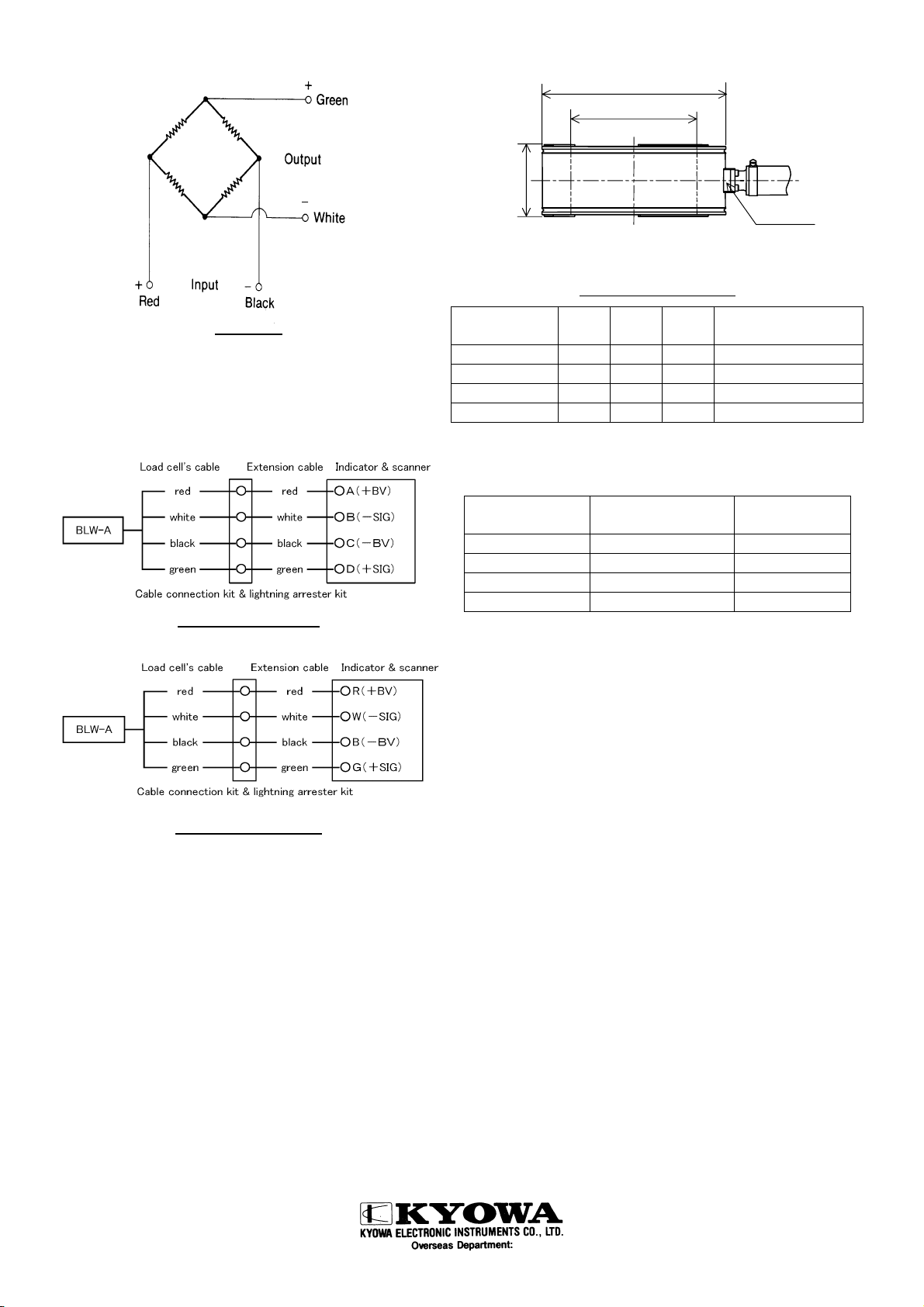
2.3 Using the tester, check that the load cell’s input / output resistance
are as follows.
Input resistance (between red and black wires) : approx. 350Ω
Output resistance (between white and green wires) : approx.350Ω
2.4 Avoid hitting or the other shocks on the load cell, or disconnection or
damage may occur. If shocks should be given to the load cell, its
performance stability may be adversely affected in long-term
continuous operation.
2.5 For transit, keep the load cell in its case. If it is carried by holding
the cable only, the cable may be damaged to cause disconnection
and / or deterioration of the insulation resistance. Measurement
may thus become impossible.
2.6 Do not disassemble the load cell.
2.7 Be sure to put the accessory cable cap on the end of the cable, and
to avoid water on the conductors.
2.8 Do not bend the cable extremely. Do not drop matters on it or tread
on it. (Keep the radius of curvature larger than 10cm when bending
the cable)
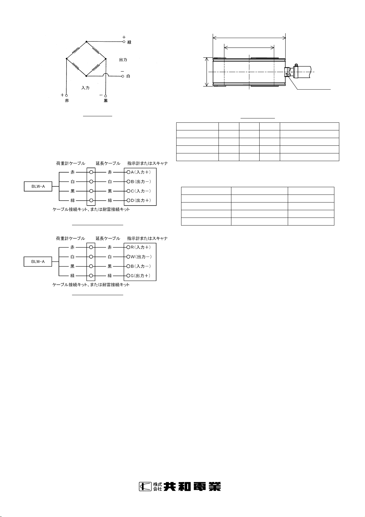
Fig.1 Installation for VSL stressbar anchor

3.Connection
3.1 Wiring of the cable of the load cell is shown below.
Fig.2 Wiring
3.2 Connections of the load cell’s input output cables with the
terminals of an indicator and with those of a scanner are
illustrated below. The indicator’s and the scanner’s terminals
respectively come with either A,B,C,D or R,B,W,G description
follow.
①A,B,C,D description
Fig.3 A,B,C,D description
②R,W,B,G description
Fig.4 R,W,B,G description
4.Conversion
4.1 Use the calibration factor described in the test data sheet to
convert a reading into a load value.
4.2 When a strain amplifier is in use, output reads in µm/m
equivalent strain (×10-6 equivalent strain). Find a load value
corresponding to µm/m. Then, obtain a load value through
multiplication using the following equation.
[ Load value(kN)] = [ Strain amplifier's output (µm/m) ]
× [ Calibration factor
(
kN/1µm/m
)
]
4.3 When using an amplifier of other type or a recorder, first find
the exact bridge exciting voltage applied. Second, find the load
value that corresponds to 1µV output voltage against 1V bridge
excitation voltage. Then, obtain the load value through
multiplication using the following equation.
[ Load value (kN) ] = [ Bridge output voltage (µV) ]
÷ [ Bridge excitation voltage (V) ]
× [ Calibration factor ( kN/1µV/V) ]
4.4 [ Calibration factor ] may be ( MN/1µm/m ) or ( MN/1µV/V ) ,
and [ Load value ] is ( MN ).
5.Dimensional drawings
* For grounding of lightning arrester kit.
Fig.5 Dimensional drawings
Model A B C
Applicable Center
Hole Diameter
BLW-A-500KN 64 φ125 φ175 φ123
BLW-A-1MN 82 φ144 φ210 φ142
BLW-A-1500KN 94 φ155 φ250 φ153
BLW-A-2MN 94 φ155 φ250 φ153
6.Specifications
Model Rated capacity
(Reference Value)
Weight
(Approx.)
BLW-A-500KN 500kN (50.99tf) 4 kg
BLW-A-1MN 1MN (102.0tf) 8 kg
BLW-A-1500KN 1500kN (153.0tf) 14 kg
BLW-A-2MN 2MN (203.9tf) 14.5 kg
●Specifications
Rated output: 1.25mV/V (2500µm/m) or more
Non-linearity: Within ±0.8%RO
Hysteresis: Within ±0.5%RO
●Environmental Characteristics
Safe temperature range: -20 to 70℃
Compensated temperature range: -10 to 60℃
Thermal effect on zero balance: ±0.05%RO/℃
Thermal effect on output: ±0.05%/℃
●Electric Characteristics
Safe excitation voltage: 15V AC or DC
Recommended excitation voltage:1 to 10V AC or DC
Input resistance : 350Ω±0.3%
Output resistance : 350Ω±2%
Cable: 0.5mm2,4-conductor chloroprene cable 1m,
ø9.6mm, bared at the tip
●Mechanical Characteristics
Safe overload rating: 150%
Structure: IP68
(Withstand water pressures up to 0.5MPa,24H,23±15℃)
Address: 2-4-3, Hitotsubashi, Chiyoda-ku, Tokyo 101-0003 Phone: 03-5226-3553 FAX: 03-5226-3566
a
b
c
o
M4 D=5 *

IM-T-248b '08.11
BLW-A センタホール型 荷重計 取扱説明書
このたびは BLW-A センタホール型荷重計をお買い上げ頂きま
して、ありがとうございます。ご使用の前には本書を必ずお
読みください。また、お読みになった後は、いつでも見られ
るところに必ず保管してください。
1.取り付け
1.1 荷重計の荷重を受ける上・下面にサビ止め塗装を施して
あります。荷重計を設置するときにはトルエンまたはア
セトンを使用して取り除いてください。サビ止め塗装を
したまま使用しますと、特性に悪い影響をおよぼします。
なお、荷重を受ける上・下面は特性向上のため研磨仕上
げになっておりますので、キズをつけぬように注意して
ください。
使用後、荷重計をご使用にならない場合、荷重を受ける
上・下面に機械油などのオイルを塗ってサビ止めとして
ください。
1.2 荷重計はアンカーに加わる荷重を検出するものです。所
定の場所に荷重計を設置し、荷重計がアンカーの中心に
来るように配置してください。この時、小石や砂、ゴミ
を挟まないように注意してください。
斜面に取り付ける場合、アンカーが荷重計の中心に来るよ
う、荷重計とアンカーの間に発砲スチロールなどを入れ
て、位置決めをしてください。
1.3 精度よく測定するため、なるべく傾斜荷重や偏心荷重が
加わらないように位置や寸法に注意してください。
1.4 荷重計に直射日光が当たらないように、発泡スチロール
等で遮蔽してください。
1.5 荷重計のケーブルは、できるだけ鋼管等の配管中に収め外部
からの力による変形や外部ノイズの防止を図ってください。
1.6 荷重計をテスタにつないで絶縁抵抗値を測定してください。
1.7 荷重計を指示計につないで初期不平衡を測定してください。
2.使用上の注意
2.1 検査成績書と製造番号を照合してください。
2.2 絶縁抵抗値を確認してください。 100MΩ以上/50V DC
絶縁抵抗を測定する場合には、絶縁抵抗計の印加電圧は 50V
以下で行ってください。
2.3 テスタで入出力抵抗をチェックしてください。
入力抵抗 赤-黒間 約 350Ω
出力抵抗 白-緑間 約 350Ω
2.4 荷重計に衝撃を与えないでください。断線・破損することが
あります。また、衝撃を与えた場合、長期にわたる連続使用
時の安定度に影響することがあります。
2.5 運搬時は、荷重計を梱包材に入れたまま運んでください。ケ
ーブルのみをもって運搬した場合、ケーブルに損傷を与え、
断線、絶縁抵抗値の低下等が生じ、測定不能となることがあ
ります。
2.6 荷重計は分解しないでください。
2.7 ケーブル先端には付属のコードキャップを被せ、心線に水が
かからないように作業してください。
2.8 ケーブルは極端に曲げたり、物を落としたり、踏みつけない
でください。最小曲げ半径は 10cm 以上です。
図1 VSLアンカ工法での使用例

3.接続
3.1 配線は下記のようになっています。
図 2 配 線
3.2 荷重計ケーブルと指示計及びスキャナーの端子の接続を
以下に示します。指示計及びスキャナーの端子には、
A,B,C,D の表示と R,W,B,G の表示のものがあります。
①A,B,C,D の場合
図3 A,B,C,D の場合
②R,W,B,G の場合
図4 R,W,B,G の場合
4.換算
4.1 出力値を荷重に換算するには、検査成績書の校正係数を
用います。
4.2 ひずみ測定器を使用した場合は、出力値がε×10-6 等価
ひずみで表示されます。等価ひずみ 1×10⁻⁶ に相当する荷
重が検査成績書に明記されていますので、乗算により荷
重が求められます。
[ 荷重(kN) ] = [ ひずみ測定器の出力ε(×10-6) ]
× [ 校正係数 ( kN /1×10-6 ) ]
4.3 その他の増幅器や記録器を使用する場合には、ブリッジ
印加電圧を正確に計る必要があります。検査成績書には、
ブリッジ印加電圧 1V を加えたときの出力電圧 1μV に相当
する荷重が明記されていますので、乗算により荷重が求め
られます。
[ 荷重(kN) ] = [ ブリッジ出力電圧(μV) ]
÷ [ ブリッジ印加電圧(V) ]
× [ 校正係数 (kN/1μV/V) ]
4.4 検査成績書の[校正係数]が( MN/1×10-6 )または、
( MN/1μV/V )の場合、[荷重]は( MN )となります。
5.外形寸法
※耐雷接続キットのアース接続用
図 4 外形寸法
型式名 A B C 適用センタホール径
BLW-A-500KN 64 φ125 φ175 φ123 以下
BLW-A-1MN 82 φ144 φ210 φ142 以下
BLW-A-1500KN 94 φ155 φ250 φ153 以下
BLW-A-2MN 94 φ155 φ250 φ153 以下
6.仕様
型式名 定格容量(参考値) 質量(約)
BLW-A-500KN 500kN (50.99tf) 4 kg
BLW-A-1MN 1MN (102.0tf) 8 kg
BLW-A-1500KN 1500kN (153.0tf) 14 kg
BLW-A-2MN 2MN (203.9tf) 14.5 kg
●性 能
定格出力 1.25mV/V(2500×10-6 ひずみ)以上
非直線性 ±0.8%RO 以内
ヒステリシス ±0.5%RO 以内
●環境特性
許容温度範囲 -20~70℃
温度補償範囲 -10~60℃
零点の温度影響 ±0.05%RO/℃以内
出力の温度影響 ±0.05%/℃以内
●電気的特性
許容印加電圧 15V AC または DC
推奨印加電圧 1~10V AC または DC
入力抵抗 350Ω±0.3%
出力抵抗 350Ω±2%
ケーブル 0.5mm2、4 心クロロプレン 1m、
外径 9.6mm、先端むき出し
●機械的特性
許容過負荷 150%
保護等級 IP68(水圧 0.5MPa、24 時間、25±15℃)
本社・工場 〒182-8520 東京都調布市調布ヶ丘 3-5-1 電話 042-488-1111
a
b
c
o
M4 深5※
This manual suits for next models
4
Other KYOWA Industrial Equipment manuals
Popular Industrial Equipment manuals by other brands

Altron
Altron AL-761-N instruction manual

Schmalz
Schmalz SCPS-L Series operating instructions

GHIELMETTI
GHIELMETTI GKV 10x40 621 SK R K Operation manual

Siemens
Siemens SIMATIC ET 200eco PN Equipment manual

cytiva
cytiva Chromaflow 50 operating instructions

Teknatool
Teknatool PRO-TEK G3 Quick start instruction manual