MRC BCT-4308 User manual

Your purchase of this
BENCH TYPE
CONDUCTIVITY METER
marks a step forward
for you into the field of
precision measurement.
Although this METER is
a complex and delicate
instrument, its durable
structure will allow
many years of use if
proper operating
techniques are
developed. Please read
the following
instructions carefully
and always keep this
manual within easy
reach.
OPERATION MANUAL
PLEASE READ THIS MANUAL CAREFULLYBEFORE OPERATION
Hagavish st. Israel 58817 Tel: 972 3 5595252, Fax: 972 3 5594529 [email protected]
MRC.1.22
Bench type, RS232/USB computer interface
TDS ( Total Dissolved Solids )
CONDUCTIVITY METER
Model : BCT-4308

TABLE OF CONTENTS
1. FEATURES................................................................1
2. SPECIFICATIONS...................................................... 2
2-1 General Specifications..........................................2
2-2 Electrical Specifications........................................ 4
3. FRONT PANEL DESCRIPTION.....................................5
4. CONDUCTIVITY/TDS MEASURING and
CALIBRATION PROCEDURE.......................................7
4-1 uS, mS measurement..........................................
.
8
4-2 TDS ( PPM ) measurement...................................9
4-3 Calibration.......................................................... 10
5. DATA HOLD, DATA RECORD, DATA LOGGER
LCD BACKLIGHT ON/OFF..........................................11
6. ADVANCED ADJUSTMENT PROCEDURE......................
.
14
6-1 Check memory space...........................................15
6-2 Clear Memory......................................................15
6-3 Set Date/Time ....................................................16
6-4 Set sampling time ...............................................16
6-5 Auto power OFF management..............................17
6-6 Select the Temp. unit to or ..........................℃℉ 17
6-7 Set CD temperature compensation factor..............18
6-8 ESC....................................................................
.
18
7. SEND THE DATA OUT FROM THE METER...................
.
19
8. RS232 PC SERIAL INTERFACE....................................21
9. BATTERY REPLACEMENT...........................................23
10. SYSTEM RESET.......................................................23
11. OPTIONAL ACCESSORIES........................................24

1. FEATURES
* Professional bench type meter with large size
LCD display with green color backlight, easy reading.
* One meter for two purpose operation :
Conductivity and TDS ( Total dissolved solids ),
measurement.
*Conductivity : 200 uS/2 mS/20 mS/200 mS.
* Measurement unit can select uS/mS ( conductivity )
or ppm ( TDS )
* Conductivity measurement can select Temp. Coefficient
of measurement solution.
*ATC for the conductivity/TDS measurement.
* Real time data logger ( record year, month, date,
hour, minute, second ), 16,000 data logger.
* Auto data record, 16,000 Data logger no.
* Wide sampling time adjustment range from one
second to 8 hours 59 minutes 59 seconds.
* Auto data logger, manual data logger.
* RS232 computer interface.
* Max., Min., Data hold.
* Can default auto power off or manual power off.
* DC 1.5V ( UM-3, AA ) x 8 PCs or DC 9V adapter in.
* Separate probe, easy for operation of different
measurement environment.
* Wide applications: water conditioning, aquariums,
beverage, fish hatcheries, food processing,
photography, laboratory, paper industry, plating
industry, quality control, school & college, water
conditioning.
1

2. SPECIFICATIONS
2-1 General Specifications
Circuit Custom one-chip of microprocessor LSI
circuit.
Display LCD size : 82 mm x 61 mm.
* with green color backlight.
Measurement * Conductivity ( uS, mS )
* TDS ( Total Dissolved Solids, PPM )
* Temperature ( , )℃℉
Temperature Automatic from 0 to 60 (32 - 140 ),℃℉
Compensation with temperature compensation factor
variable between 0 to 5.0% per C.
Sampling Time
Auto data logger :
of Data Logger 1 sec to 8 hour 59 min. 59 sec.
Manual data logger :
Set sampling time to 0 second.
Data Hold Freeze the display reading.
Memory Recall Maximum & Minimum value.
Power off Auto shut off saves battery life or
manual off by push Button.
@
Can default auto power or manual
power off.
@
When default auto power function,
power will off automatically after
10 minutes, if no Button be pressed.
Sampling Time Approx. 1 second.
of display
Data Output RS 232/USB PC computer interface.
* Connect the optional RS232 cable
UPCB-02 will get the RS232 plug.
* Connect the optional USB cable
USB-01 will get the USB plug.
2

Operating Main instrument 0 to 50 .℃
Temperature Probe 0 to 60 .℃
Operating Less than 80% R.H.
Humidity
Power Supply DC 1.5 V battery ( UM3 ) x 8 PCs,
( Heavy duty type ).
DC 9V adapter input.
@ AC/DC power adapter is optional.
Power Operation ( LCD backlight ON ) :
Consumption Approx. DC 23 mA
Operation ( LCD backlight OFF ) :
Approx. DC 8 mA
Power OFF ( only internal clock running ) :
Approx. DC 1.8 uA.
Weigh
t
* meter
1049 g/2.3 LB.
Dimension
Meter
225 X 125 X 64 mm
@ Meter Probe
( 8.86 X 4.92 X 2.52 inch )
Accessories Instruction manual.....................
.
1 PC
Included Conductivity/TDS probe..............
.
1 PC
Optional * 1.413 mS Conductivity Standard
Accessories Solution..............................
.
CD-14
* Carrying case......................
.
CA-3K
* AC to DC 9V adapter.
* RS232 cable, UPCB-02.
*USBcable,USB-01
* Data Acquisition software,
SW-U801-WIN.
*Data Logger software, SW-DL2005.
3

2-2 Electrical Specifications (23±5 )℃
Conductivity ( uS, mS )
Range Measurement Resolution Accuracy
200 uS 0 to 200.0 uS 0.1 uS
2 mS 0.2 to 2.000 mS 0.001 mS ± (2% F.S.+1d)
20 mS 2 to 20.00 mS 0.01 mS * F.S. - Full scale
200 mS 20 to 200.0 mS 0.1 mS
* Temperature Compensation :
Automatic from 0 to 60 ( 32 - 140 ), with temperature℃℉
compensation factor variable between 0 to 5.0% per C.
* The accuracy is specified under measurement value 100 mS.≦
* mS - milli Simens * @ 23± 5℃
TDS ( Total Dissolved Solids )
Range Measurement Resolution Accuracy
200 PPM 0 to 132 PPM 0.1 PPM
2,000 PPM 132 to 1,320 PPM 1 PPM ± (2% F.S.+1d)
20,000 PPM 1,320 to 13,200 PPM 10 PPM * F.S. - Full scale
200,000 PPM 13,200 to 132,000 PPM 100 PPM
* Temperature Compensation :
Automatic from 0 to 60 ( 32 - 140 ), with temperature℃℉
compensation factor variable between 0 to 5.0% per .℃
* The accuracy is specified under measurement value 66,000 PPM.≦
* PPM - parts per million * @ 23± 5℃
Temperature
Function Measuring Range Resolution Accuracy
℃0 to 60℃℃ 0.1 ℃±0.8℃
℉32 to 140℉℉ 0.1 ℉±1.5℉
* @ 23± 5℃
4

3. FRONT PANEL DESCRIPTION
Fig. 1-1
5

Fig. 1-2
3-1 Display
3-2 Power Button ( LCD Backlight Button )
3-3 HOLD Button ( ESC Button )
3-4 REC Button ( Enter Button )
3-5 Zero Button
3-6 Function Button ( Range Button )
3-7 Send Button ( Clock Button )
3-8 SET Button ( Logger Button )
3-9 Up Button▲
3-10 Down Button
▼
3-11 Probe input Socket
3-12 RS232 socket
3-13 Reset button
3-14 DC 9V power adapter socket
3-15 Stand
3-16 Battery Cover/Battery compartment
6

4. CONDUCTIVITY/TDS MEASURING
and CALIBRATION PROCEDURE
The meter default function are following :
*The display unit is set to conductivity ( uS, mS ).
*The temperature unit is set to .℃
*Temp. compensation factor is set to 2.0% per C.
*Auto range.
*Auto power off.
*The sampling time of data logger function is
2 seconds.
Fig. 2
If the meter is first time to connect
the conductivity probe, it should
execute the calibration procedures
before operation, the calibration
procedures refer chapter 4-3, page 10.
7

4-1 uS, mS measurement
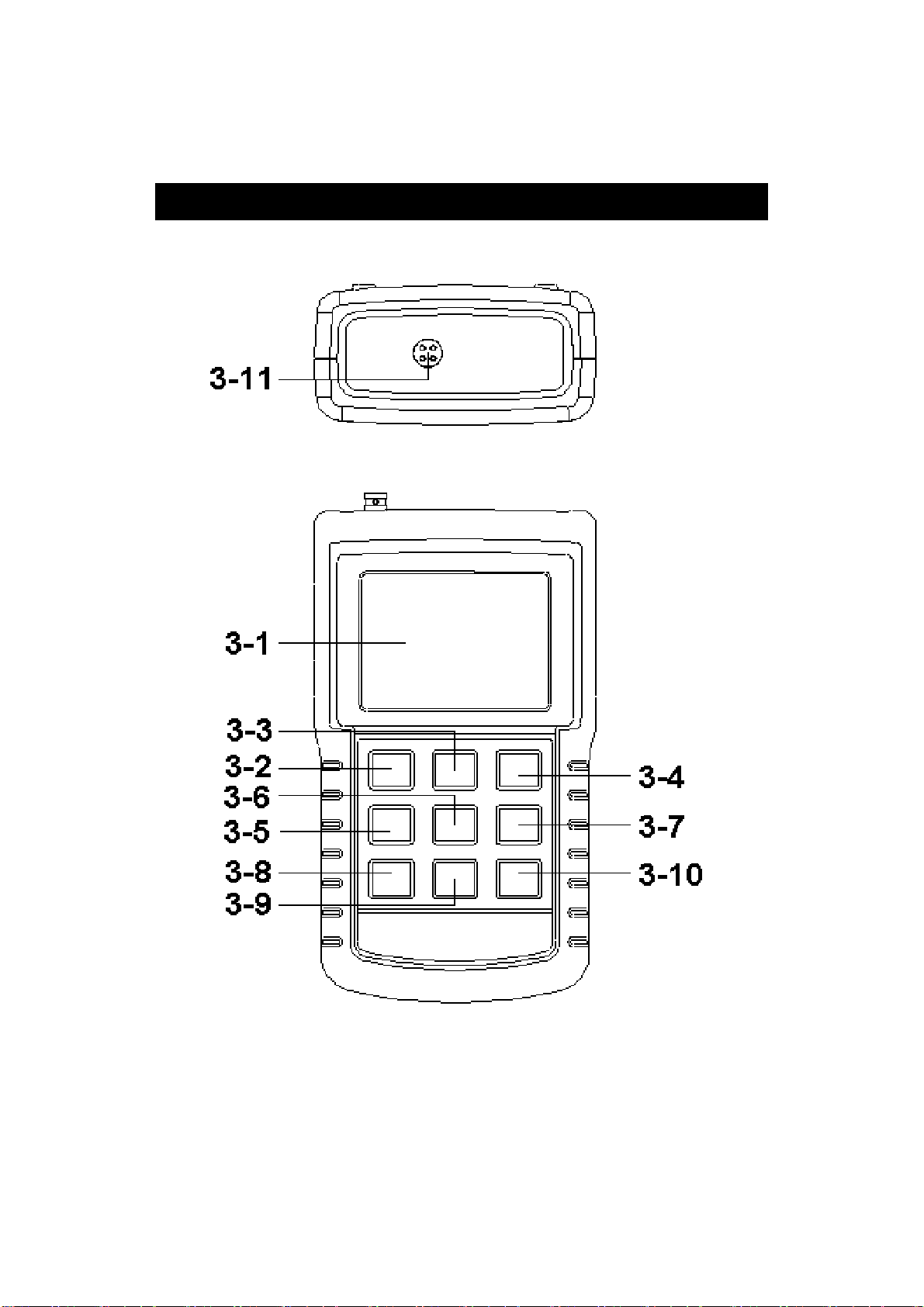
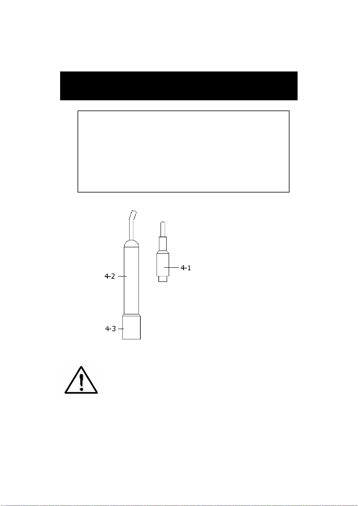
1)Prepare the Conductivity Probe ( included, CDPB-03 ),
install the " Probe Plug " ( 4-1, Fig. 2 ) into the
" CD Socket " ( 3-11, Fig. 1 ).
2)Power on the meter by pressing " Power Button "
( 3-2, Fig. 1 ) once.
The Display will show " uS " and " Temp. " indicator.
3)Hold the " Probe Handle " ( 4-2, Fig. 2 ) by hand
and let the " Sensing head " ( 4-3, Fig. 2 )
immersed wholly into the measured solution. Shake
the probe to let the probe's internal air bubble drift
out from the sensing head.
4)Display will show the conductivity mS ( uS ) values.
at the same time the left bottom display will show the
Temp. value of the measured solution.
Manual range operation
The meter is default to be used for the auto range
mode.
If intend to let the meter be used under the
manual range mode, the procedures are following :
*
Press the " Range Button " once a while, it can
change the range, the range name ( Auto, 200 uS, 2
mS, 20 mS, 200 mS ) will show under the
measurement value.
* If the display shows " ", it indicates an
overload condition, select the next higher range.
* If the display shows " ", it indicates an
out-of-range, select the next lower range.
* If intend to change the operation mode from Manual
range back to Auto Range, press the " Range Button
" ( 3-6, Fig. 1 ) once in sequence until the Display
show the text " Auto ", release the " Range Button ",
the meter is ready for the Auto range mode again.
8

Change the Temp. unit to ℉
If intend to change the Temp. unit from to , please℃℉
refer page 17, chapter 6-6 ( Temp. Unit Default Setting )
Change the Temp. Coefficient Factor
The default Temp. compensation factor value of the
measurement solution is to 2.0% per . If intend to℃
change it, please refer page 18, chapter 6-7 ( Temp.
Compensation Factor Setting ).
Zero adjustment
If the probe not immerse the measurement solution
and display not show zero value, pressing the " Zero
Button " ( 3-5, Fig. 1 ) > 10 seconds continuously will
let display show zero. The zero function only valid when
the no zero value less than 1.0 uS.
4-2 TDS ( PPM ) measurement
The measuring procedures are same as above
4-1 Conductivity ( uS, mS ) measurement,
except to change the display unit from uS, mS to PPM.
The procedures are :
* Press the " Function Button " ( 3-6, Fig. 1 ) > 2
seconds continuously until the Display show the text
" tdS ", then release the " Function Button " will enter the
the TDS measurement function.
* Under the TDS measurement, press the " Function
Button " ( 3-6, Fig. 1 ) > 2 seconds continuously until
the Display show the text " Cd ", then release the
" Function Button " will enter the Conductivity
measurement function again.
9

4-3 Calibration
1)Prepare the standard conductivity solution ( optional )
For example :
2 mS range calibration solution :
1.413 mS Conductivity Standard Solution, CD-14
200 uS range calibration solution :
80 uS Conductivity Standard Solution
20 mS range calibration solution :
12.88 mS Conductivity Standard Solution
or other Conductivity Standard Solution
2)Install the " Probe Plug " ( 4-1, Fig. 2 ) into the
" CD Socket " ( 3-11, Fig. 1 ).
3)Power on the meter, set the mode to the conductivity
measurement ( uS, mS ).
4)Hold the " Probe Handle " ( 4-2, Fig. 1 ) by hand
and let the " Sensing head " ( 4-3, Fig. 1 ).
immersed wholly into the measured solution. Shake
the probe to let the probe's internal air bubble drift
out from the sensing head.
Display will show the conductivity mS ( uS ) values.
5)Use the two fingers to press the " REC Button " ( 3-4,
Fig 1 ) and " HOLD Button " ( 3-3, Fig. 1 ) at the same
time. the display will show the following screen as
example, release the both fingers.
Cd
CAL
6)Use " Button " ( 3-9, Fig. 1 ), " Button " ( 3-10,▲▼
Fig. 1 ) to adjust the up display value exact same as
the standard conductivity value. Press the " Enter
Button " will save the calibration data and finish
the calibration procedures.
10

*
If only intend to make the one point calibration,
just execute the 2 mS range ( 1.413 mS Cal. )
is enough.
*
Multi-points calibration procedures should
execute the 2 mS range ( 1.413 mS Cal. )
calibration at first, then make other ranges
(20 uS range, 20 mS range or 200 mS range )
calibration procedures following if necessary.
5. DATA HOLD, DATA RECORD,
DATA LOGGER,
LCD BACKLIGHT
5-1 Data Hold
During the measurement, press the " Hold Button " ( 3-3,
Fig. 1 ) once will hold the measured value & the LCD will
display a " HOLD " symbol.
Press the " Hold Button " once again will release the data
hold function.
5-2 Data Record ( MAX, MIN reading )
* The data record function records the maximum and
minimum readings. Press the " REC Button " ( 3-4, Fig.
1 ) once to start the Data Record function and there
will be a " REC " symbol on the display.
* With the " REC " symbol on the display :
a)Press the " REC Button " ( 3-4, Fig. 1 ) once, the
" REC MAX " symbol along with the maximum value
will appear on the display.
If intend to delete the maximum value, just press
the " Hold Button " ( 3-3, Fig. 1 ) once, then the
display will show the " REC " symbol only & execute
the memory function continuously.
11

b)Press the " REC Button " ( 3-4, Fig. 1 ) again, the
" REC MIN " symbol along with the minimum value
will appear on the display.
If intend to delete the minimum value, just press
the " Hold Button " ( 3-3, Fig. 1 ) once, then
the display will show the " REC " symbol only &
execute the memory function continuously.
c)To exit the memory record function, just press the
" REC " Button > 2 seconds at least. The display will
revert to the current reading.
5-3 Data Logger
The data logger function can save 16,000 measuring
data with the clock time ( Real time data logger, build
in clock ( hour-min.-sec., year-month-date ).
The data logger procedures are as following :
a)If push the " Logger Button " ( 3-8, Fig. 1 ) once will
show the sampling time value on the bottom left
display then disappeared.
b)Press the " REC Button " ( 3-4, Fig. 1 ) once to
start the Data Record function and there will be a
" REC " symbol on the display.
Auto Data Logger ( Sampling time set from
1 second to 8 hours 59 minutes 59 seconds )
Press the " Logger Button " ( 3-8, Fig. 1 ) once to start
the Auto Data Logger function, The upper display will
show " DATALOGGER " indicator along with " REC "
marker.
* Pause the data logger function :
Press the " Logger Button " ( 3-8, Fig. 1 ) once.
* Exit the data logger function :
Press the " REC Button " ( 3-4, Fig. 1 ) > 2 seconds.
12

Manual Data Logger ( Sampling time set to 0
second )
Press the " Logger Button " ( 3-8, Fig. 1 ) once will
save the data one time into the memory.
Beeper will sound and the upper display will show
" DATALOGGER " indicator along with " REC " marker.
* Exit the data logger function :
Press the " REC Button " ( 3-4, Fig. 1 ) > 2 seconds.
d
)
Memory full
Under execute the data logger, if the bottom right
display show the " Full ", it indicate the memory data
already over 16,000 no. and the memory is full.
e)During execute the Auto Data Logger function, press the
Logger Button " ( 3-8, Fig. 1 ) once will stop to execute
" the data logger function, the " DATALOGGER " indicator
will be disappeared.
If press the " Logger Button " ( 3-8, Fig. 1 ) once again
will continuous the Auto Data Logger function.
Remark :
1)
If intend to change the data logger sampling time,
please refer chapter 6-4, page 16.
2)
If intend to know the space of balance data numbers
into the memory IC, please refer chapter 6-1, page 15.
3)
If intend to clear the saving data from the memory
please refer chapter 6-2, page 15.
5-4 LCD Bcklight ON/OFF
After power ON, the " LCD Backlight " will light
automatically. During the measurement, press the
" Backlight Button " ( 3-2, Fig. 1 ) once will turn OFF the
" LCD Backlight ".
Press the " Backlight Button " once again will turn ON the
" LCD Backlight " again.
13

6. ADVANCED ADJUSTMENT
PROCEDURES
Under do not execute the Datalogger function,
press the " SET Button " ( 3-8, Fig. 1 ) continuously at
least two seconds will enter the " Advanced Setting " mode,
press the " SET Button " ( 3-8, Fig. 1 ) once a while
in sequence to select the 13 main function, the
display will show :
SPACE..
.
Check memory space
Clr........
.
Clear Memory
dAtE.....
.
Set clock time ( Year/Month/Date, Hour/Minute/
Second )
SP-t......Set sampling time ( Hour/Minute/Second )
PoFF.....Auto power OFF management
t-CF......Select the Temp. unit to or℃℉
PEr C....
.
Set CD temperature compensation factor, CD only
ESC...... Escape from the advanced setting
b.During execute the " Advanced Setting " function,
if press " ESC Button " ( 3-3, Fig. 1 ) will exit the
" Advanced Setting " function, the LCD will return
to normal screen.
14

6-1 Check memory space
When the display show " SPACE "
To check the balance data numbers that exist into the
memory ( allow the balance memorize data no. ).
@The bottom value XXXXX is the balance data numbers,
for example XXXXX=15417.
6-2 Clear Memory
When the display show " CLr "
1)To delete the existing save data numbers from the
memory.
2)Push ENTER Button to enter " Memory clear " function.
Use the " Button " ( 3-9, Fig. 1 ) or " Button " (▲▼
3-10, Fig. 1 ) to select the upper value to " yES " or
" no ".
yES - Intend to clear the Memory.
no - Not to clear the Memory.
3)If select the upper to " yES ", press the " Enter Button
" ( 3-4, Fig. 1 ) once will clear the Memory, the bottom
value will show " 0 ".
Press the ESC Button once to quite and return to
the main measurement screen.
15

6-3 Set Date/Time ( Year/Month/Date,
Hour/Minute/ Second )
When the upper display show " dAtE "
1)Use the " Button " ( 3-9, Fig. 1 ) or " Button "▲▼
( 3-10, Fig. 1 ) to adjust the value ( Setting start from
Year value ). After the desired value is set, press the
" Enter Button " ( 3-4, Fig. 1 ) once will going to
next value adjustment ( for example, first setting
value is Year then next to adjust Month, Date, Hour,
Minute, Second value ).
Remark :
The adjusted value will be flashed.
2)After set all the time value ( Year, Month, Date, Hour,
Minute, Second ), press the " SET Button " ( 3-8, Fig.
1 ) once will save the time value, then the screen will
jump to Sampling time " setting screen ( Chapter 6-4 ).
Remark :
After the time value is setting, the internal clock will
run precisely even Power off if the battery is under
normal condition ( No low battery power ).
6-4 Set sampling time ( Hour/Minute/Second )
When the upper display show " SP-t "
1)Use the " Button " ( 3-9, Fig. 1 ) or " Button "▲▼
( 3-10, Fig. 1 ) to adjust the value ( Setting start from
Hour value ). After the desired value is set, press the
" Enter Button " ( 3-4, Fig. 1 ) once will going to next
value adjustment ( for example, first setting value is
Hour then next to adjust Minute, Second value ).
16

Remark :
The adjusted value will be flashed.
2)After set all the sampling time value ( Hour, Minute,
Second ), press the " SET Button " ( 3-8, Fig. 1 ) once
will save the sampling value with default then the
screen will jump to " Auto power OFF " setting
screen ( Chapter 6-5 ).
6-5 Auto power OFF management
When the lower display show " PoFF "
1)Use the " Button " ( 3-9, Fig. 1 ) or " Button "▲▼
( 3-10, Fig. 1 ) to select the upper value to " yES " or
" no ".
yES - Auto Power Off management will enable.
no - Auto Power Off management will disable.
2)After select the upper text to " yES " or " no ", press the
" Enter Button " ( 3-4, Fig. 1 ) will save the setting
function with default.
6-6 Select the Temp. unit to or℃℉
When the lower display show " t-CF "
1)Use the " Button " ( 3-9, Fig. 1 ) or " Button "▲▼
( 3-10, Fig. 1 ) to select the upper Display text to " C " or
" F ".
C - Temperature unit is ℃
F - Temperature unit is ℉
17

2)After Display unit is selected to " C " or " F ", press the
" Enter Button " ( 3-4, Fig. 1 ) will save the setting
function with default.
6-7 Set CD temperature compensation factor
When the lower display show " PEr C "
1)This function only for the Conductivity ( TDS ) mode of
adjusting the probe's Temp. compensation value in
%/per unit. The default value is 2 %/ per .℃℃
2)Use the " Button " ( 3-9, Fig. 1 ) or " Button "▲▼
( 3-10, Fig. 1 ) to select the upper value to the desired
Temp. compensation value ( %/per ), then press the℃
" Enter Button " ( 3-4, Fig. 1 ) will save the setting
value temporally.
6-8 ESC
When the display show " ESC "
When the Display show the text " ESC ", then press the
" Enter Button " ( 3-4, Fig. 1 ) will finish the Advanced
Setting procedures and return to the normal measuring
screen.
18
Table of contents
Other MRC Measuring Instrument manuals
Popular Measuring Instrument manuals by other brands

Frederiksen
Frederiksen 513610 quick guide

R&S
R&S FPC-Z10 Teaching Kit Getting started

HELWIG CARBON
HELWIG CARBON BPK-Probe operating guide

Watts
Watts HF Scientific AccUView LED Ex installation instructions

TSI Instruments
TSI Instruments ALNOR MicroManometer AXD 550 owner's manual

Kamstrup
Kamstrup OMNIPOWER installation manual