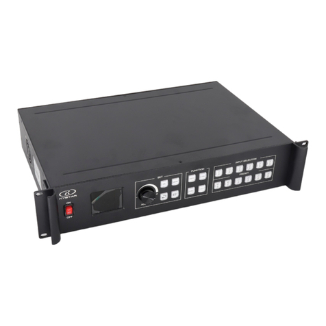
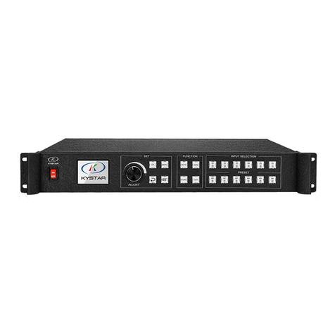
Kystar KS9000 User manual

KYstar KS9000 plicing processing platform
Multi-Screen Splicer Processor
1
Safety precautions
Danger
●High voltage exists in the device and non-professional maintenance
personnel shall never open its back cover, lest risks happen.
Warning
●This is not a waterproof device, so appropriate waterproof measures
shall be taken in a damp environment;
●Never have this device kept near any fire source or high
temperature environment;
●If this device gives out strange noise, smoke or smell, unplug the
battery socket immediately and contact with its dealer;
●Never plug/unplug any charged VGA or DVI signal cable.
Caution
1. Please read this Manual carefully before operation and keep it
properly for future use;
2. In the case of lightning or long-term downtime, please unplug the
power socket;
3. This device is not suitable for non-professional debugging or
operation, so please use it under the guidance of professionals;
4. Never force anything into this device from its air vent, lest device
damages or accidents happen;
5. This device should not be placed or used near water or wherever

KYstar KS9000 plicing processing platform
Multi-Screen Splicer Processor
2
wet;
6. This device should not be placed or used near cooling fins or
wherever hot;
7. Please clear up and keep the power lines properly to prevent
damages;
8. If the following situations occur, unplug the power socket of this
device and contact for maintenance:
●When this device is contaminated with liquid;
●When this device is dropped or its framework is damaged;
●When this device suffers from significant dysfunction or obvious
performance deterioration

KYstar KS9000 plicing processing platform
Multi-Screen Splicer Processor
3

KYstar KS9000 plicing processing platform
Multi-Screen Splicer Processor
4
Table of Contents
Safety precautions.......................................................................................1
I. Hardware.................................................................................................2
1. Back panel.......................................................................................2
2. Wiring diagram ...............................................................................3
II. Software Installation ..............................................................................3
III. Equipment Connection..........................................................................9
1. Software open .................................................................................9
2. Software connect...........................................................................10
I. Wiring....................................................................................11
II. Change the local access IP...................................................11
III. Set up communications.......................................................12
I. Wiring....................................................................................13
II. Change the COM port..........................................................13
III. Set up communications.......................................................13
IV. Software Settings ................................................................................14
1. Output port settings.......................................................................14
2. Window setup ...............................................................................17
3. Mode Save/Call.............................................................................21
1. Mode Save ............................................................................21
II. Mode Call.............................................................................22
V. Characteristic Functions.......................................................................23
1. Insert Image ..................................................................................24
2. Insert Text .....................................................................................25
3. OSD Text Setting..........................................................................25
VII. FAQ...................................................................................................28

KYstar KS9000 plicing processing platform
Multi-Screen Splicer Processor
1
This product is the first truly multi-window splicer in the industry, and as a
professional video processing and control equipment, it can act as a splicer controller
specially targeting such equipment as oversized screens, projection and LCD.
The multi-window splicer processor researched and developed by our company
uses a pure FPGA hardware architecture subject to no operating system and the
whole system can work in a completely closed environment, so it features simple
operation and high stability.
It has been widely used in monitoring/dispatching command centers and video
conference centers, etc.
As the management software designed for this platform, the user can complete
parameter settings and operation management of hardware equipment by means of
this software and the whole operating process is completely intuitive and convenient.
It is applicable to such operating systems as Windows XP, Windows 7, Windows
8 and Windows 10.
The following instructions are all based on the operating system of Windows 7
as an example.

KYstar KS9000 plicing processing platform
Multi-Screen Splicer Processor
2
I. Hardware
1. Back panel
1. Input board/card: able to support input of such signals as DVI, VGA, CVBS,
HDMI, SDI, IP stream and 4K and able to be extended to 216 channels at most.
2. I/O board/card: full DVI-I output, able to support 30 channels of splicer
output at most
3. Control board/card: including power switch, COM port, Ethernet port and
USB
4. Power supply: at most four redundant power supply sources

KYstar KS9000 plicing processing platform
Multi-Screen Splicer Processor
3
2. Wiring diagram
II. Software Installation
Insert the CD attached in the distribution box of this product into the CD driver
and you can view the CD contents in the file manager.
Double-click the “Software Installer”and it will pop up the following interface:

KYstar KS9000 plicing processing platform
Multi-Screen Splicer Processor
4
Select the installation language, click “OK”and it will enter such installation
wizard as follows:

KYstar KS9000 plicing processing platform
Multi-Screen Splicer Processor
5
Click “Next” and it will pop up the interface as follows for you to read the
installation license agreement:
Please read the installation license agreement carefully; if you accept the
agreement, please click on “I accept the agreement”, then click “Next” and it will
pop up the destination position interface as follows:

KYstar KS9000 plicing processing platform
Multi-Screen Splicer Processor
6
Select your desired installation path, click “Next” after confirmed and it will
pop up the interface “Select Start Menu Folder”as follows:

KYstar KS9000 plicing processing platform
Multi-Screen Splicer Processor
7
Select the shortcut path and click “Next” after confirmed.
To continue, click “Next”

KYstar KS9000 plicing processing platform
Multi-Screen Splicer Processor
8
Confirm the installation information and click “Install” to start the installation
process:

KYstar KS9000 plicing processing platform
Multi-Screen Splicer Processor
9
Wait until the system pops up the following information and it indicates that the
installation is successful:
Till now, the software has been completely installed; double-click the software
shortcut icon on the computer desktop to enter the software Settings interface.
III. Equipment Connection
1. Software open
Double-click the software shortcut on the desktop to open the software and it
will enter the software start page as shown in the figure below:

KYstar KS9000 plicing processing platform
Multi-Screen Splicer Processor
10
For the first use, there is no password so just click “OK” directly; if a user
password has been set, the software control/setting will not be accessible unless the
correct password has been entered.
Click “OK”to enter the software main interface as shown in the figure below:
2. Software connect
Click “Equipment”, select “Video Wall”, then click “Equipment Connect” and it
will pop up the “Communicate Setting” window as shown in the figure below:

KYstar KS9000 plicing processing platform
Multi-Screen Splicer Processor
11
This software has “Net Connect”and “COM Connect”available; when different
“Connect”modes are selected, different preparations will be necessary.
(1) Select the “NET Connect”.
I. Wiring
Use a CAT5 network cable and connect its two ends to the processor LAN port
and the PC network port respectively (or connect via a switchboard).
II. Change the local access IP
In the operating system of Windows 7, click “Start →Control Panel →View
Network Tasks →Change Adapter Settings” to find out the LAN and you can right
click it to select properties.
Double-click the Internet protocol version 4 (TCP/IPv4) to change
corresponding data.
Note: If the equipment IP is segment 0 by default and the IPs of other equipment
can be ensured within the same field and numbered differently, proper access is
available. If you want to change the IP network segment, you need to change it in the
current software settings.

KYstar KS9000 plicing processing platform
Multi-Screen Splicer Processor
12
III. Set up communications
During software communication, select the “NET Connect”, directly click “OK”,
and if the connection is successful, it will pop up an information box as shown in the
figure below; then just click “OK”.

KYstar KS9000 plicing processing platform
Multi-Screen Splicer Processor
13
(2) Select “COM Connect”.
I. Wiring
Connect both ends of the RS230-RJ11 cable attached to the processor COM1
port and the PC serial port respectively (if there is no 9-pin serial port, a serial
port-USB adapter shall be used to change it into a USB which can be connected to
the PC USB port).
II. Change the COM port
During software communication, select “COM Connect”:
In general, the software can identify the COM port automatically and the user
can just click “OK”with no setting necessary. But in some cases, a PC may have
several COM port working at the same time to result in software identification error;
then, you need to select a COM port (Please try one by one).
III. Set up communications
During software communication, select the “NET Connect”, directly click “OK”,
and if the connection is successful, it will pop up an information box as shown in the
figure below; then just click “OK”.

KYstar KS9000 plicing processing platform
Multi-Screen Splicer Processor
14
IV. Software Settings
1. Output port settings
After the equipment is successfully connected, click on the “Screen Config
Setting”in the “Main Functional Area” and it will pop up the “Screen Config
Setting”interface; the six dotted boxes feature one-to-one correspondence to the
equipment output ports (from left to right from the rear) and you can set the load of
each output port and the arrangement modes of such output ports on this interface as
shown in the figure below:

KYstar KS9000 plicing processing platform
Multi-Screen Splicer Processor
15
The “Screen Resolution” refers to the maximum resolution each port can output
and is generally greater than or equal to the resolution of each transmitter card or
display screen.
The “Row”and “Column”can be set as required, the “1920”and “1080”after
“Screen Resolution”can be changed freely according to the actual loaded pixels,
double-click such numerical values and you can change them.
For example: If the screen size is 6016 * 2080 with six transmitter cards loaded,
then the loading scale and arrangement should be determined as shown in the figure
below:

KYstar KS9000 plicing processing platform
Multi-Screen Splicer Processor
16
2048
1040
1040
2048
2048
2048
1920
1920
1040
1040
Then, you need to complete such settings as follows in the interface of “Screen
Config Settings”:
P: If “All Screen Brightness Syn”is checked, it indicates that the following
modifications of the color values target all output ports but if not, you can adjust the
color of a single output port.
Set the arrangement modes and loaded pixels of the output port and then click
Other manuals for KS9000
1
Table of contents
Other Kystar Computer Hardware manuals
Popular Computer Hardware manuals by other brands

Advantech
Advantech PCA-6742 Series Startup manual

Allen-Bradley
Allen-Bradley SLC 5/01 installation instructions

ADLINK Technology
ADLINK Technology 6216-GL Series user manual

National Instruments
National Instruments NI-9252 CALIBRATION PROCEDURE

ICP vortex Corporation
ICP vortex Corporation 32-Bit PCI - Wide/Ultra2 SCSI specification

Cypress Semiconductor
Cypress Semiconductor CY7C1410JV18 Specification sheet