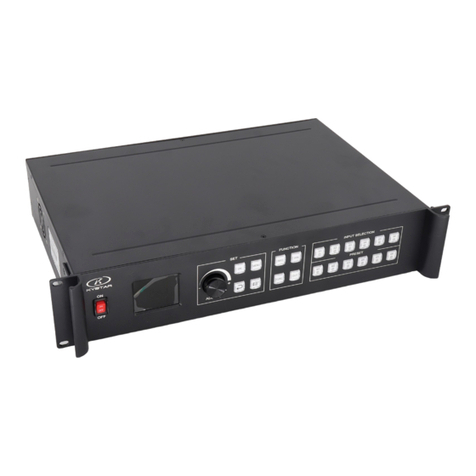
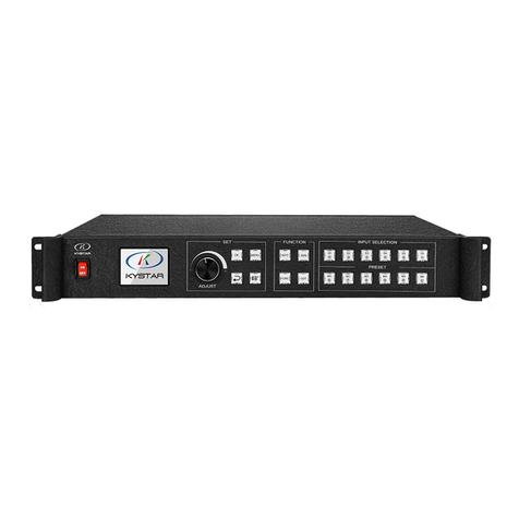
Kystar KS910P User manual

Multi-Image
Splicing
Processor
(XA)
Operation Manual

Statement
Thank you for choosing our products.
All rights of the manual are reserved by the company and no copy, delivery, distribution or
storage of any form of the content is allowed without written permission from the company. The
company reserves the right of modifications and improvements of any product function described
in the document without prior notice.
Any possible affiliated control software of the product is only for your usage while all its
rights are reserved by the company. You are allowed to copy the software but only limited to your
personal usage. If the software is to be applied to other purposes, in particular commercial
purposes, please contact us. The company reserves the right of investigate and affix legal
liabilities of any infringement act.
Please read the manual carefully before using. Any improper operation may cause damage to
the product. It is operated with electricity and sufficient attention should be attached. Our
company bears no responsibility for any property loss and personal injury incurred from any
improper operation failing to follow the instructions in the manual. If the provision herein
conflicts with local laws or regulations, the latter shall prevail.
It means that you accept the statement above if you use the product. If not, please contact
with the seller and return the product following relevant procedures.
Certification Description
“CE” Certification
EN 55022:2010
EN 55024:2010
EN 61000-3-3:2013
EN 61000-3-3:2014
EN 0950-1:2006+A11:2009+A1:2010+A12:2011+A2:2013
“FCC” Certification
FCC Part 15
ANSI C63.4:2014
“ROHS” Certification
EPA 3050B:1996,EN1122:2001
EPA 3052:1996,EPA 3060A
EPA 7196,EPA 3540C,EPA 8270C
Version Information
Version: v1.0
Issue Date: June, 2016

SAFETY PRECAUTIONS
For your safety, please read this section carefully.
Power
Power supply of the device for normal operation is 100-200V
AC. Please make sure that the product is operated within the
voltage range.
High voltage
High voltage devices are contained.
Do not dismantle without professionals
The device is not equipped with repair parts which is aimed
for maintenance by customer himself, so do not open chassis
and operate by yourself which may lead to unrecoverable
damage of the device. If maintenance is required, please
contact after-sales service personnel.
Ensure sound grounding
For your safety, please ensure that power cable is grounded
soundly
Keep away from strong magnetic field, engine and transformer
For normal operation of the device, please keep it away from
strong magnetic field, motor and transformer.
Guard against damp
Keep operational environment dry. If the device becomes
damping inadvertently, do not power the device and use it
after being dried.
Keep away from explosives
Please do not use the product in combustible or explosive
environment.
Prevent liquid or conductive fragments getting into the chassis
Liquid or metal fragments should be stopped from getting into the
case. If so, the device should be powered off immediately and power
supply can only be allowed after clearance of foreign bodies.

Table of Contents
1. Product Introduction....................................................................................................................... 1
2. Hardware Introduction.................................................................................................................... 2
2.1 Front Panel............................................................................................................................ 2
2.2 Back Panel.............................................................................................................................3
3. Device Debugging...........................................................................................................................5
3.1 Device Connection................................................................................................................5
3.2 Debugging Procedure............................................................................................................6
3.3 Case explanation................................................................................................................... 9
3.4 Function Key:......................................................................................................................15
3.5 Advanced Menu.................................................................................................................. 18
4. Technical Parameters.................................................................................................................... 20
5. FQAs............................................................................................................................................. 21
Appendix: Graphics copy mode and extended mode setting........................................................... 23
1. AMD Video Card.................................................................................................................. 23
2. NVIDIA Video Card............................................................................................................. 24

Multi-Image Splicing Processor
1
1. Product Introduction
The multi-image mosaic processor is a high-end video processing equipment developed and
manufactured by our company for LED large screen display, performance and leasing, conference
room, studio and so on.
The product adopts CPT+ FST splicing technology targeted for small pixel LED display to
guarantee uniformity and synchronization of splicing. The Super Resolution Zoom-in Technology
can help eliminate jaggies and reduce the fuzzy sense and out-of-focus phenomenon due to image
magnification.
The product enjoys the following features:
1. Support various signal input includes conventional DVI, VGA, HDMI, CVBS, SDI and IP;
support 4K Ultra HD input and realize large screen point-to-point display.
2. Stand-alone can support user-defined layout of pixel 10.4 million and support output
pixels up to 15360 horizontally or 6144 vertically.
3. Support free-form six-image layout and realize central control of main screen, side screen,
floor tile or canopy of the stage in an easy way.
4. Support signal echoing and view real-time input and output signals by software.
5. Support multi-image preview and output monitoring.
6. Support seamless switch of signal and mode and provide over 10 kinds of transition
special effects.
7. Support overlay of multi-group editable and global image-texts and captions.
8. Support luma key, image transparency adjustment and edge feathering.
9. Support warm backup of multi-level input signal.
10. Support multi-machine synchronous cascade output.

Multi-Image Splicing Processor
2
2. Hardware Introduction
2.1 Front Panel
① ② ③ ④⑤ ⑥⑦ ⑧
⑨⑩ ⑪ ⑫ ⑬
1. POWER: Power switch of 220V AC. ON indicates power connected, OFF power
disconnected .
2. LCD color screen: Information display screen showing device information and debugging
information.
3. ADJUST: Adjusting knob which can be used for selecting information on color screen and
adjusting various parameters rapidly.
Counterclockwise rotation means up and clockwise refers down. Rotation downward
means confirmation.
4. OK: OK key for confirming debugging information.
5. MENU: Menu key for access to main menu for device debugging.
6. INFO: Information query key for real-time condition of input signal.
7. WIN: Image information key for displaying and switching image signal source.
8. S1-S6: Signal source key. Signal source key on main menu refers to input source of back
device and that on parameter input interface refers to
number 1 to 5 and backspace key.
9. : Back or cancel key.
10. : Wizard key. Click for the Wizard Mode.

Multi-Image Splicing Processor
3
11. FUNC: Common Function key for entering into common function interface.
12. OUT: Output option key for selecting output of blank screen, blue screen or normal
screen.
13. M1-M6: Quick mode call key. Main menu interface is quick mode call key and
parameter input interface
shows number 6 to 0 and clear key.
2.2 Back Panel
① ② ③ ④ ⑤
⑥ ⑦ ⑧ ⑨ ⑩
1. CARD: Transmitting card slot that enables recharging of the transmitting card into the
processor.
2. MONTOR: Pre-monitor channel for monitoring input signal source or output interface
information.
3. OUTPUT: Programmatic output channel for pure digital DVI-D output and transmitting
card connection.
4. LAN1: 100MB network control port which can realize device debugging by software with
its connection with computer 100MB network interface.
5. AC 100-220V: Power switch which can be connected to 100-220V AC.
6. INPUT S5, S6: Expanded input which is able to expand two regular ports or one 4KHDMI
input.
7. INPUT S1-S4: Regular input includes one group DVI, one group HDMI, two groups VGA

Multi-Image Splicing Processor
4
and CVBS.
8. LOOP: DVI-Loop output which loops S1-DVI signal and is used for multi-machines
cascade.
9. LAN2: Gigabit network control port which can be used for device debugging and also
echoing function.
10. COM: RS232 control port which connects with computer serial port and can debug
device by PC Software.

Multi-Image Splicing Processor
5
3. Device Debugging
3.1 Device Connection
Device connection could be divided into three parts: power connection, signal connection and
control connection (used for software debugging).
Power connection: device power supply. Connection method: connect power cord to power
plug.
Signal connection: the method transferring signal from signal source to LED large screen.
Connection method: signal source (e.g.: computer)→Mosaic Processor→Transmitting
card→Large screen.
Control connection: connect computer with device control port and debug device connection
method. There are three connection methods:
(1)Connect 100 mbit network control port with splicer LAN1 port, which can set device
software.
(2)Connect computer gigabit network port with splicer LAN2 port, which can not only set
device but also echo signal source image.
(3)Connect one crystal head of serial port line which is randomly donated by device with
splicer COM port, and plug DB9 into computer serial port. Any of the three methods realizes
device software control.
Connection diagram is as follows:
Display
Computer
Mosaic
Transm
itting

Multi-Image Splicing Processor
6
S1
Confirm
Cancel
×1
×10
×100
OUT1
OUT2
Screen Parameters
Horizontal Size:
1920
Vertical Size:
1080
Turn knob to select
output
Select by finger
Device Mode
Copy Output
Horizontal
Mosaic
Vertical
Mosaic
OUT
Note:
All output displays
are the same.
3.2 Debugging Procedure
Step 1: Click “MENU” to enter into main menu interface and click “Device Mode” to select
splicing mode: copy mode, horizontal mosaic, and vertical mosaic.
Note: Copy Mode: all output contents are consistent; horizontal mosaic: contents of all
outputs are arranged horizontally; vertical mosaic: contents of all outputs are arranged vertically;
Step 2: select suitable splicing mode and click “OK”; get back to main menu interface to
select “Screen parameter” and enter into its setting interface. Set loaded screen point of each
output interface and click “Confirm” after inputting, and then screen splice is finished.
Note: there are two ways for number input:
(1) Adjust by rotate knob. Step length can be adjusted by “×1”“×10”“×100”, for
instance, “×100”means that number of rotate knob increases by 100 each time.
Input by number of the front panel. For example, of the key refers to figure 1.
Step 3: get back to main menu interface to select “Image layout” and enter into image
number selecting interface to select image number required to be set.

Multi-Image Splicing Processor
7
×1
×10
×100
Image Parameters
Select by finger key
Horizontal
Position: 0
Vertical
Position: 0
Horizontal Size:
1920
Vertical Size:
1080
Turn knob to select
image
Click “OK” to adjust
Image 2
Image 3
Image 1
Clipped View
Select by finger key
Image 1
Image 3
Image 2
×1
×10
×100
Horizontal
Vertical
Turn knob to select
image
Click “OK” to adjust
Vertical Size:
Horizontal
Image Layout
Image 1
S1
Layout 1
Layout 2
Layout 3
Note: In case of signal image, skip this step. For multi-image, it’s OK if image number and
item requirements are in consistent. Following operations can be taken when layouts are not
consistent.
Step 4: Click “OK” and return to main menu interface; select “Image parameter” and enter
into its setting interface to set size and position of each image.
Step 5: Click “Menu” and return to main menu interface; select “Clipped view” to enter into
its setting interface to set size and position of each image.

Multi-Image Splicing Processor
8
User Mode
User Mode 1
Device Mode 2x2
Image Layout 1
Mode 1
Mode 2
Mode 3
Mode 4
Mode 5
Mode 6
Mode 7
Mode 8
Image 1
S1
M1
⑥
M5
○0
M6
○
c
M4
⑨
M3
⑧
M2
⑦
Save Setting
Current mode does
not exist!
Save Mode 1
Device Mode
Image Layout
Mode 1
Mode 2
Mode 3
Mode 4
Mode 5
Mode 6
Mode 7
Mode 8
Note: This step should be skipped if full display of signal source is required on large screen;
while if certain signal source of multi-image is needed to be extracted, only setting of signal
source image is required; if horizontal size or vertical size is 0, it means no local extraction is
required in this direction.
Step 6: Click “MENU” and return to main menu interface; select “Save setting” to enter into
Data storage interface; select any mode and click “OK” to save data.
Note: Mode 1 is default startup data of device boot; it’s suggested that the most common
mode or that required by device boot should be saved to Mode 1.
At this point, basic device debugging is completed. If there is other requirement, repeat the
operation and save it as other mode.
After device debugging, just call saved data according to different condition requirements in
later stage.
Data call is divided into forms:
(1) For Shortcut key call, only click of “M1-M6” in front panel is required, which is
convenient when mode scenario is few.
(2) For User mode call of Main Menu, click “MENU” and select “User Mode” to enter into
its extraction interface. Then select desired mode and click “OK”.

Multi-Image Splicing Processor
9
Device Mode
Copy
Output
Horizonta
l Mosaic
Vertical
Mosaic
OUT1
Note:
All output
OUT2
896
3.3 Case explanation
Device debugging steps are explained by following cases.
Case 1: screen size is 2112×896 and loading transmitting card is shown as
picture below:
Requirement: whole computer desktop should be displayed completely.
960 1216
Diagram of loaded transmitting card Display image
Debugging Procedure:
Step 1: click “MENU” and enter into main menu interface to select “Horizontal mosaic” of
the first item “Device mode”.
Note: as two transmitting cards are in the 1x2 arrangement, horizontal mosaics are needed
then.
Step 2: Click “OK” to return to main menu interface; select “Large screen parameters” to set

Multi-Image Splicing Processor
10
Screen Parameters
OUT1
OUT2
Select by finger key
Horizontal Size:
1920
Vertical Size:
1080
Turn knob to select
output
Confirm
Cancel
×1
×10
×100
Save Setting
Save Mode 1
Device Mode
Image Layout
Current mode does
not exist!
Mode 1
Mode 2
Mode 3
Mode 4
Mode 5
Mode 6
Mode 7
Mode 8
size of each output interface.
Note: Input according to corresponding transmitting card size of each output interface. For
OUT1, its horizontal size is 960 and vertical size 896; for OUT2, they are 1216 and 896 respectively.
Step 3: After inputting, select “Confirm” and return to main menu interface. The large screen
splicing is finished, select signal source needed to display on screen and click corresponding key.
E.g.: for display of computer signal on large screen and connection of computer DVI interface
with “S1-DVI” port of the back device, just click “S1” in the front which means choosing the
signal to display on the screen.
Step 4: After selecting signal and normal display of large screen, save all setting data. Click
“MENU” to enter into main menu interface, and then get into “Save setting” interface to select
“Mode 1” and click “OK”. Things will be fine when it suggests saving successfully.
Note: Mode 1 is default startup data of device boot; it’s suggested that the most common
mode should be saved to Mode 1 and the device can save 32 kinds of modes at most.
Case 2: Screen size is 1792×1344 and loaded transmitting card is shown as

Multi-Image Splicing Processor
11
Device Mode
Copy Output
Horizontal
Mosaic
Vertical
Mosaic
OUT1
Note:
All output interfaces
OUT2
picture below:
Requirement: 1) Whole computer desktop should be displayed completely.
2) Screen is divided into three parts with proportion of 1:2:1.
1792
Diagram of loaded transmitting card
Display image 1 Display image 2
Debugging Procedure:
Step 1: Click “MENU” to enter into main menu interface. Select “Device mode” and then
“Vertical Mosaic”.
Note: as two transmitting cards are in vertical arrangement, horizontal mosaics are needed
then.
704
640

Multi-Image Splicing Processor
12
Screen Parameters
OUT1
OUT2
Select by finger key
Vertical Size:
1080
Confir
Cancel
×1
×10
×100
Horizontal Size:
1920
Turn knob to select
output
Save Setting
Save Mode 1
Device Mode
Image Layout
Mode 1
Mode 2
Mode 3
Mode 4
Mode 5
Mode 6
Mode 7
Mode 8
Current mode does not
exist!
Step 2: Click “OK” to return to main menu interface; select “Large screen parameters” to set
size of each output interface.
Note: Input according to corresponding transmitting card size of each output interface. For
OUT1, its horizontal size is 1792 and vertical size 704; for OUT2, they are 1792 and 640
respectively.
Step 3: After inputting, select “Confirm” and return to main menu interface. The large screen
splicing is finished, select signal source needed to display on screen and click corresponding key.
E.g.: for display of computer signal on large screen and connection of computer DVI interface
with “S1-DVI” port of the back device, just click “S1” in the front which means choosing the
signal to display on the screen.
Step 4: After selecting signal and normal display of large screen, save all setting data. Click
“MENU” to enter into main menu interface, and then get into “Save setting” interface to select
“Mode 1” and click “OK”. Things will be fine when it suggests saving successfully.

Multi-Image Splicing Processor
13
Image Layout
Layout 1
Layout 2
Layout 3
S1
Image 1
S1
Image 2
S1
Image 3
Image Parameters
Image 1
Select by finger key
Image 2
×1
×10
×100
Image 3
Turn knob to select
image
Vertical Size:
1080
Vertical
Position: 0
Horizontal
Horizontal
Note: Mode 1 is default startup data of device boot; it’s suggested that the most common
mode should be saved to Mode 1 and the device can save 32 kinds of modes at most.
For above operation which has fulfilled the first requirement of the program, namely splicing
of the whole screen, image is displayed completely and correct data are saved. For the second
requirement which is that screen is divided into three parts with proportion of 1:2:1, only further
setting on operation above is needed.
Step 5: Click “MENU” and enter into main menu interface and select “Image layout” then
Layout 3.
Note: Default layout of the device is three equal parts. If it is desired, there is no need to carry
out step 6. If not, the following operations are required.
Step 6: Click “OK” to return to main menu interface and select “Image parameter” to enter
into its setting interface. Set the following parameters:
Image
Properties
Horizontal
Position
Vertical
Position
Horizontal
Size
Vertical Size
Image 1
0
0
448
1344
Image 2
448
0
896
1344
Image 3
1344
0
448
1344

Multi-Image Splicing Processor
14
WIN
Image Switch
Image 2
S1
Image 3
S1
Image 1
S1
Note: The full screen size is 1792x1344 and image proportion is required as 1:2:1, so the sizes
of the three images are respectively 448, 896 and 448. As the left images starts from the far left,
its horizontal position is 0. The middle image follows the left image, so its horizontal position is
448. The right image follows the middle, so its horizontal position is 448+896=1344. The vertical
direction always starts from the top, so the vertical position is 0. In summary, both horizontal and
vertical positions of image 1 are 0 and horizontal and vertical sizes are 448 and 1344 respectively;
Horizontal and vertical positions of image 2 are respectively 448 and 0 and horizontal and vertical
sizes are 896 and 1344 respectively. Horizontal and vertical positions of image 3 are respectively
1344 and 0 and horizontal and vertical sizes are 448 and 1344 respectively.
Step 7: According to operation above, screen body has been divided into three images with
proportion of 1:2:1. Default display content of each image is S1. If different signal sources should
be designated for each image, click of front panel to enter into image switch interface. Select
image by rotate knob and choose signal by click of S1-S6 of front panel. E.g.: if signal of image 2
is S6, click “WIN” to enter into image switch, then adjust rotate knob to image 2 (it’s selected if
padded) and finally click “S6” of front panel. After selecting each image, save final data which is
the same with step 4.
Up to now, program debugging is finished. If any display method is needed in later stage, it’s
just OK to call saved mode. There are two ways for mode call. When mode number is not big, just
click M1-M6 of front panel which are shortcut key for mode call; when mode number is big (over
6), user mode call should be made. Click “MENU” to enter into main menu interface, then select

Multi-Image Splicing Processor
15
Information-signal Condition
Image Switch
Image 1
S1
Image 2
S1
Image 3
S1
User Mode
Image 1
S1
User Mode 1
Device Mode 2x2
Image Layout 1
Mode 1
Mode 2
Mode 3
Mode 4
Mode 5
Mode 6
Mode 7
Mode 8
“User mode” and call needed mode.
3.4 Function Key:
Below are detailed explanations of function keys:
INFO: Information query key. Click this key and enter into its interface showing whether all
signal sources are inputting normally. Its interface is shown as below. Red light means signal is
lost while green one shows signal is normal.
WIN: Image key. Click this key to enter into its interface and signal source selection can be
made in the following interface. Taking image 3 as instance, click “WIN” to enter into image
switch interface which shows current signal sources of three images. If signal source switch is
needed, rotate the knob first to select the image and switch by “S1-S6” of the front panel.

Multi-Image Splicing Processor
16
Output Condition Control
Black
Blue
Norm
Note: Display black
screen
OUT: Output condition key. Click the key to enter into its interface with three output options:
blank screen, blue screen and normal screen. Selection of blank screen means all output interfaces
and large screen are blank; blue screen means all those are blue; and normal screen refers to
normal image output.
FUNC: Function key. Click this key to enter into its interface. Common functions include:
brightness adjustment, special effect switch, VGA adjustment, image matting setting, edge feather,
transparency setting, intelligent warm backup, preview monitor, IP setting, serial port, freeze
frame, local and global, color space, input brightness and switch time. The following are
explanations of those common functions.
1. Brightness adjustment
The device supports 1-255 stairs brightness adjustment. Brightness of all screen body can
be adjusted synchronously to meet customers’ different brightness adjustment requirements
for different conditions.
2. Special effect switch
The device supports switching of 16 kinds of special effects: fade in/out, seamless
straight cut, vertical or horizontal comb, round cut-in or cut-out,
diamond cut-in or cut-out and cross of every side.
All those can meet requirements of different scene switch.
3. Special effect time
Set image switch times or switch time among different modes with the range of 0.2s-3s.
4. VGA adjustment
Table of contents
Other Kystar Computer Hardware manuals