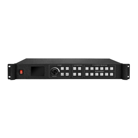
Kystar KLS24 User manual

KLS24
24 lan ports two-in-one video controller
Version: v1.1
release date: November 2021
Manual

Version record·
Version
Change details
release time
V1.0
first release
2021.10.25
V1.1
Correct size data
2021.11.18

Security Considerations
Critical Insurance
●The equipment has high voltage, not professional maintenance personnel should not open the back cover,
in order to avoid danger.
Notice
●This equipment is not waterproof equipment, in humid environment, please do water treatment;
●This device is prohibited from approaching an ignition or high temperature environment;
●If the device emits a strange noise, smoke or smell, should immediately unplug the power Plug
and contact the Distributor;
●prohibit live unplug VGA,DVI signal cable.
Note
1、Please read this manual carefully before use, and save it for later use;
2、In the case of lightning or long-term use, unplug the power plug;
3、this equipment is not suitable for non-professional operation debugging, please use under the
guidance of professionals;
4、DO not plug any object from the vent hole of this device to prevent damage or accident;
5、It is not advisable to place this equipment in near water or other humid places;
6、It is not advisable to place this equipment in the heat sink or other high-temperature places;
7、please properly arrange and put the power cord to prevent breakage;
8、unplug the device and entrust maintenance if the following conditions are present:
●when a liquid is spilled into this device
●When this device falls or the chassis is damaged
●When this device appears to have a significant functional anomaly or a significant
performance difference

Catalog
PREFACE: EQUIPMENT DEBUGGING PROCESS.............................................................................1
1、VIDEO PROCESSOR SETTING.............................................................................................................1
2、CONTROL SYSTEM SETTING..............................................................................................................3
1、PRODUCT DISCUSSION.............................................................................................................. 6
2、FEATURES...................................................................................................................................... 7
3、TECHNICAL PARAMETER............................................................................................................8
4、WORKING DIAGRAM.................................................................................................................. 9
5、PANEL STRUCTURE....................................................................................................................10
CABLE CONNECTION DIAGRAM................................................................................................................. 11
INSTALLATION STEPS....................................................................................................................... 11
7、VIDEO PROCESSOR SOFTWARE DEBUGGING INSTRUCTIONS............................... 12
7.1 OPEN SOFTWARE..........................................................................................................................12
7.2 SOFTWARE CONNECTION..............................................................................................................13
7.2.1 select NET connect
...........................................................................................................
13
7.2.2 Select COM Connect
........................................................................................................
14
7.3 OUT PORT SETTINGS.................................................................................................................... 15
7.4 OPEN WINDOW........................................................................................................................... 17
7.MODE SAVE AND CALL.....................................................................................................................20
7.5.1 Mode save
.........................................................................................................................
20
7.5.2 mode call
...........................................................................................................................
20
8、CONTROL CARD SOFTWARE DEBUGGING INSTRUCTIONS..................................... 21
1、SOFTWARE CONNECTION.............................................................................................................. 21
2、RECEIVING CARD PARAMETER SETTINGS......................................................................................... 22
3、SCREEN CONNECTION.................................................................................................................23
4、SAVE PARAMETER......................................................................................................................... 24
9、FAQ...............................................................................................................................................25

24 network port 2-in-1 controller product manual
1
Preface: Equipment Debugging Process
Open “kystar” video processor software→screen configuration→open
window→select signal source→save mode →open “kystar control system”
software→expert debug→Receiving card debugging→screen connection→total save
parameter.
1、video processor setting
1、IP address:change PC IP and KSV24 on the same network segment。
KLS24 default IP address:192.168.0.100。
2、
software connect:
open PC software to debug
(kystar software),
connect device,
select Ethernet to connect.

KLS24manual www.kystar.com.cn
2
3、screen configuration setting :click“setting”“screen configuration ,Change the
loading of each output port and the arrangement of the output ports according to the
actual output.
4、open window:Click on the upper left corner to open a new screen or hold down the
left mouse button and drag in the operation area. When a rectangle is drawn, release
the left button and a window will be created. Double-click the signal source on the left
to switch the signal.

KLS24manual www.kystar.com.cn
3
5、save mode:Click Save mode in the “setting”, select mode ID, and enter a mode
name.
2、control system setting
1、open kystar control system of “kystar”software,click“kystar control system
software”enter control card debug interface,first time debug KLS24,click“666888”
in keyboard after open software,select network cable direct connection mode,select
“directly connected to sending device”.
2、On the receiving card interface, add module configuration information through

KLS24manual www.kystar.com.cn
4
"module selection" or "settings", and then fill in the content of the single-card loading
area according to the receiving card loading situation. If there is a previously saved
configuration file, it can also be loaded on this interface and sent to the receiving card
parameters.
3、On screen connection interface, set the number of card columns and card rows
according to the positions of all receiving cards, click the “setting”connection,
complete the connection according to the prompts and modify the load size of each
receiving card.

KLS24manual www.kystar.com.cn
5
4、Finally, after confirming that the screen is displayed normally, click "Solid All" to
complete all debugging operations of KLS24.

KLS24manual www.kystar.com.cn
6
1、Product discussion
With the rapid development of the LED display industry and the continuous expansion of application
requirements, various control requirements for large-screen control systems have emerged. However, due to the
limitations of the large-screen control system in image processing, picture control and signal format conversion,
the LED large-screen control system has some weak links and cannot meet the needs of users. The main problems
are as follows:
1.The signal source access format of the LED large screen control system is limited. Currently, only digital
DVI signals are generally used. Many signal sources (such as VGA, etc.) cannot be displayed on the LED large
screen directly through the control system;
2.The traditional signal acquisition card has poor image processing effect, which causes great loss to the
clarity of the picture when the signal format is converted;
3.The LED large screen control system can only capture the image corresponding to the number of points on
the LED large screen for display, and in some customer sites, it is necessary to display the screen of any size or
complete computer desktop at will;
4.With the continuous reduction of the distance between the LED screens and the continuous increase of the
number of screen points, the era of single-card loading and single-screen display of a single screen will soon cease
to exist, and more application requirements and display requirements will be highlighted. LED large screen control
system It needs better cooperation with other peripheral equipment to fulfill the needs of customers.
In response to the above problems, our company has independently developed a variety of video processing
products. The product adopts advanced control and image processing technology, which can not only realize fast
and stable switching between signals, but also perform multi-level processing on the screen.
KLS24 is a control processor designed for live performance LED large screen. Adopt the industry's top design
technology, in line with international and industry standards. Pure hardware FPGA design architecture, all boards
of the product adopt modular design, and input boards can be freely selected. It is a 3U device that supports
4K@60Hz input in the industry.
The whole machine has 13.8 million pixels of custom loading, which can meet the needs of most of the scene.

KLS24manual www.kystar.com.cn
7
2、Features
Pure hardware FPGA architecture: no CPU, no core, no poisoning and crash risk, and the system runs stably.
Mean time to failure MTBF>30,000 hours, support 365 × 24 hours of continuous operation.
A single network port can carry 650,000 pixels, and the whole machine can carry a maximum of 13.8 million
pixels. The width can reach up to 24,000 points, and the height can reach up to 24,000 points. The single
machine has 24 network port outputs.
Multi-picture display, the whole machine can display up to 16 windows at the same time, and the single-layer
output board can display up to 8 windows at the same time.
Equipped with 4K@60Hz module, supports DP1.2, HDMI2.0 input, the maximum resolution supports
4096×2160@60Hz or 7680×1080@60Hz.
Software control, the user can directly connect to the host computer software or control the local area
network, and supports B/S architecture, users can use the browser to access the device through the local area
network or the Internet for management.
Group screen management, the device supports two groups of screen management, and the corresponding
output port resolution of each group of screens can be set separately to meet the mixed control of various
display terminals in special-shaped screens and complex scenes.
Super Resolution zoom technology, video compensation processing algorithm, no size limit when the screen
is reduced, and retains image details, reducing the out-of-focus phenomenon after the screen is enlarged
multiple times.
CrossInt splicing processing technology effectively eliminates splicing dislocation and asynchrony.
Mode call function, users can preset multiple display layout plans, which can be called with one key when
using, and supports up to 200 modes.
The mobile terminal management function can be used for parameter setting and signal management of the
device through the mobile terminal device APP software, supporting Android and IOS.
Seamless switching function, no black screen, no flickering, no jamming in the whole process when
switching the signal of the screen or calling the mode.
EDID management function, by changing the EDID information of the device, the user can set the input
resolution of the device by himself.

KLS24manual www.kystar.com.cn
8
3、Technical parameter
The video processor adopts the latest patented video processing technology, and has the video
conversion capability of any format input and corresponding format output. Video signals
including DVI, HDMI, DP, etc. can be processed and enhanced to meet customer application
requirements. The detailed specifications are as follows:
Input port
Type
quantity
Specification
DVI-D(24+1)
2
·The maximum supported resolution is 2048×1152@60Hz, and
support custom resolution
·Compatible with HDMI1.3 and below
HDMI 1.3
2
·The maximum supported resolution is 2048×1152@60Hz, and
support custom resolution
·Compatible with HDMI1.3 and below
HDMI2.0
1
·The maximum supported resolution is 4096×2160@60Hz or
7680×1080@60Hz, supports custom resolution, the horizontal width
is up to 8000 pixels, and the height is up to 4000 pixels
DP1.2
1
·The maximum supported resolution is 4096×2160@60Hz or
7680×1080@60Hz, supports custom resolution, the horizontal width
is up to 8000 pixels, and the height is up to 4000 pixels
Output port
Type
quantity
Specification
LAN
24
·LAN port, used to transmit data to the receiving card
·A single network port can load up to 650,000 pixels, with a
maximum width of 4000 and a maximum of 4000
·The maximum load of the whole machine is 13.8 million pixels, the
maximum width is 24000, and the maximum is 24000
Control port
Type
quantity
Specification
RJ11(RS-232)
1
Data transfer rate is 4800, 9600, 19200, 38400, 57600, 115200
(BT)
RJ-45
1
100M
Machine specification
input power
100-240V AC~50/60Hz 6.6A
Operating temperature
0-45℃
Dimensions
482.6×315.7×138.4mm(L×W×H)
Net weight
10KG
Power
80W

KLS24manual www.kystar.com.cn
9
4、Working diagram

KLS24manual www.kystar.com.cn
10
5、panel structure
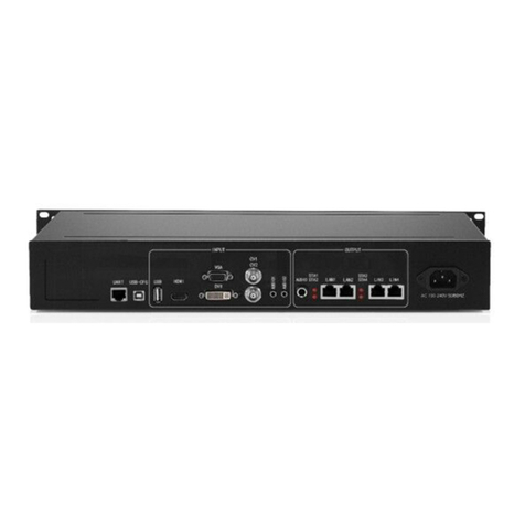
1. Input board card:4K@60Hz module,support DP1.2,HDMI2.0 input,max
support resolution 4096×2160@60Hz or 7680×1080@60Hz.
2. Output board card :24 pcs lan cable out.
3. Control board: including power switch, COM port, network port, USB.
4. Power supply: 100-240V AC~50/60Hz 6.6A,not support backup power supply.
③
②
①
④

KLS24manual www.kystar.com.cn
11
6、cable connection and Installation
Cable connection diagram
Installation steps
1、Wiring as shown in the figure, connect the output port of the server graphics card to
the input port of the KLS24 controller;
2、Then connect cable as shown in the figure, connect the control computer to the
LAN control port of the device through the network cable, and connect the output
network port of the KLS24 controller to the receiving card;
3、Make sure that the wiring is correct and then power on and open the gold card
debugging software. The software can correctly identify the model of the sending card
and the number of receiving cards, and the debugging can be done normally.

KLS24manual www.kystar.com.cn
12
7、video processor software debugging instructions
7.1 open software
Double-click the software shortcut on the desktop, open the software, and go to the software
start-up page.
As shown in the following illustration:
The first use of no password direct click to determine, if you set the user password requires
the correct password to enter the software control / settings.
Click OK to enter the software main interface.
As shown in the following illustration:

KLS24manual www.kystar.com.cn
13
7.2 Software connection
,Click Device Selection, select Video wall , and then click Connecting Devices , Pop-up
Communication Settings window, as shown in the following illustration:
The software can choose NET or COM two ways to connect, choose a different connection way
to prepare for different.
7.2.1 select NET connect
(1)Wiring
Use CAT5 network cable, one end connected to the processor LAN Port, one end is connected
to PC the network port of the, which can also be connected through a switch.
(2)Modify Local Area Connection IP
In Windows system, go to Start →Control Panel →View Network Tasks →
Change Adapter Settings, you can find Local Area Connection, right-click Local Area
Connection and select Properties, the following dialog box will pop up, double-click
Internet Protocol Version 4 (TCP/IPv4), and set the The data modification and other
IP addresses in the same network segment of the splicer, for example, the default IP
address of the splicer is 192.168.0.100, at this time, the IP address of the computer
can be modified to 192.168.0.123, and the subnet mask is 255.255.255.0. As shown
below.

KLS24manual www.kystar.com.cn
14
Note: Device IP address defaults to 0 network segment, other device's IP the guarantees that the same field and
different numbers are available for normal communication. To change The network segment of IP, you need to
change the software settings now.
(3)Establish communication
in software communication, Select NET Connect , and click directly OK , if the connection
succeeds, a prompt box will pop up, as shown in the following figure, and click OK .
7.2.2 Select COM Connect
(1)Wiring
Use random distribution RS230--RJ11 connector, one end attached to the processor's COM1 Port,
one end is connected to PC Serial Port (if no nine-pin serial port to use serial port to turn
USB Convert header to USB up PC 's USB port).
(2)Modify COM Port
When software communicates, Select COM Connect :

KLS24manual www.kystar.com.cn
15
In General, the software automatically recognizes COM port, users do not need to set, click
to confirm. However, in some cases the PC machine may have more than one com port at work, causing
software recognition errors, at this point you need to select com Port (Please try it in turn).
(3)Establish communication
When software communicates, Select NET Connect , and click directly OK , if the connection
succeeds, a prompt box will pop up, as shown in the following figure, and click OK .
7.3 Out port settings
Click after device connection succeeds Primary Ribbon under Screen Configuration , pop-up
screen parameter setting interface , the six dotted field word box in the operation area
corresponds to the device output port (see left to right) one by one, the load on each outlet
and the outlet arrangement are set in the interface. As shown in the following illustration:

KLS24manual www.kystar.com.cn
16
Screen Resolution The maximum resolution that the can output for each outlet, typically greater
than the resolution of each card or display.
Row and Columns set on your own, above the layout diagram 1920 and the on the left 1080 the
can be modified according to the actual number of load points, double-click the value to modify.
For example: Screen size is 6016*2080 , with six send cards, with load size and arranged as
shown in the following figure:
Then, the screen parameter settings interface requires the following settings:
Table of contents
Other Kystar Controllers manuals
Popular Controllers manuals by other brands

Giacomini
Giacomini PM100W Installation

Mitsubishi Electric
Mitsubishi Electric MELSERVO-J2S-S061 Specifications and Instruction Manual

Thermo Scientific
Thermo Scientific PRO902C instruction manual

Technische Alternative
Technische Alternative UVR65 Programs, Installation, Electric Connection User Guide

AudioCodes
AudioCodes RX-PAD quick guide

Hayward
Hayward CAT 2000 W3CATPP2000 owner's manual