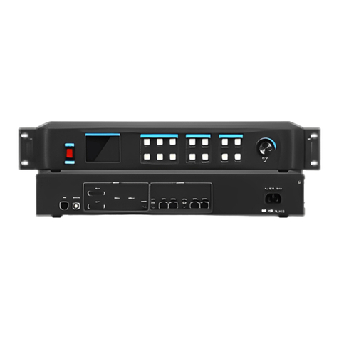
Kystar LS6 User manual

Two in One Controller
With Eight Network Port
LS6
Manual

Beijing KYSTAR Technology Co., Ltd.
Safety precautions
Danger
● There is high voltage in the equipment. Non-professional maintenance
personnel should not open the back cover to avoid danger.
Warning
● This equipment is not waterproof equipment, please do waterproof treatment in wet
environment;
● This device is not allowed to get close to fire or high temperature environment;
● If the device emits strange noise, smoke or strange smells, unplug the power plug
immediately and contact the dealer.
●It is strictly forbidden to plug VGA, DVI and HDMI signal cables on line.
Attention
1 Please read this manual carefully before use ,and keep it for future;
2 this equipment is not suitable for non-professionals to operate and debug,please use under the guidance of
professionals;
3 this equipment is not suitable for non-professionals to operate and debug, please use under the guidance of
professionals;
4 Do not insert anything into the vent hole of the device to avoid damage or accidents to the device;
5 It is not appropriate to place the device on a heat sink or other high-temperature place;
6 It is not suitable to place this equipment in near water or other damp places;
7 Please properly organize and place the power cord to prevent damage;
, the power plug of the device should be unplugged and commissioned for maintenance:
8 If the following conditions exist,the power plug of the device should be unplugged and commissioned for
maintenance;
●When liquid splashes into the device
●When the device is dropped or the chassis is damaged
●When the device has obvious abnormality or performance is significantly
deteriorated

catalog
II、PRODUCT CHARACTERISTICS..................................................................................... 2
V. PANEL STRUCTURE ....................................................................................................... 6
FRONT PANEL............................................................................................................................6
BACK PANEL ..............................................................................................................................7
6. WIRING AND INSTALLATION .......................................................................................... 8
WIRING DIAGRAM .......................................................................................................................8
VII、EQUIPMENT DEBUGGING ........................................................................................ 9
WIZARD MODE ................................................................................................................................9
VIII、CONTROL MENU .................................................................................................... 16
IX、FREQUENTLY ASKED QUESTIONS ........................................................................... 19
X、METHOD OF IMPORTING BOX FILES ......................................................................... 22

1
I. Product Discussions
With the rapid development and application demand of LED display industry, various control
requirements for large screen control system emerge as the times require. However, due to the
limitations of the large screen control system in image processing, picture control and signal
format conversion, there are some weak links in the large screen control system of LED, which
can not meet the needs of users. The main problems are as follows:
1.The signal source access format of large LED screen control system is limited. At present,
only digital DVI signal is commonly used. Many signal sources (such as VGA) can not be
displayed directly on the large LED screen through the control system.
2.The image processing effect of traditional signal acquisition card is poor, which causes
great loss to the clarity of the picture while converting the signal format.
3.The large LED screen control system can only capture the corresponding points of the large
LED screen for display, while in some customer sites, it is necessary to display any size or
complete computer desktop screen at will.
4.The large LED screen control system can only capture the corresponding points of the large
LED screen for display, while in some customer sites, it is necessary to display any size or
complete computer desktop screen at will.
In view of the above problems, our company independently developed a number of video
processing products. The product adopts advanced control and image processing technology,
which can not only realize switching between signals quickly and steadily, but also process
multi-level pictures. In addition, the product can be controlled by keyboard and PC computer on
the device, which makes the operation simple and convenient.

2
II、Product characteristics
1.Support the independent operation of the control panel, the design of knobs and digital keys
makes the equipment easier to use.
2.Supporting the software control of the host computer to realize visual and fast operation.
3.Support fade-in and fade-out perfect switching;
4.Supporting brightness and contrast, enhancing image display effect;
5.Supports arbitrary scaling of the screen size (the picture can be adjusted point by point, the
minimum can be reduced to one pixel);
6.Supporting motion compensation, the picture does not appear tail;
7.Supporting noise reduction and reducing noise stains;
8.Supporting 6 channels of high definition video signal input and 8 channels of network port
output;
9.Supports a maximum input resolution of 1920 x 1080, a custom output resolution of 4.8
million, a maximum width of 3840, a maximum of 1536;
10.Support painting support brightness, contrast one key adjustable, support one key black
screen, ensure fast response on the scene;
11.PIP and POP function, double pictures roaming and overlapping arbitrarily;
12.Supporting the setting of planned tasks, it can realize the function of timing switching.
13.Supporting call use record and engineering lock function;
14.Support four audio input and one audio output.
15.Support multi-machine cascade;
16.It supports the function of redistribution configuration and readback configuration, and
can be maintained without host computer.
17.Support keyboard lock function to prevent misoperation of site personnel after
construction debugging;
18.Supports the preservation and invocation of five scenario modes.
19.Support navigation (intelligent settings) shortcut settings;
20.International 1.5U standard height, easy to carry and install;

3
III. Technical Indicators
Video processor adopts the latest patented video processing technology and has the ability
of video conversion with arbitrary format input and corresponding format output. Video signals
including CVBS (composite video), HDMI, VGA (RGB) and DVI-D can be processed and
enhanced to meet customer application needs. Detailed specifications are as follows:
CVBS(BNCinput)
(Number of Inputs)
2
(Supported Standards)
PAL/NTSC
(Signal Level)
1Vpp±3db (0.7V Video+0.3v Sync )
75 ohm
HDMI input
(Number of Inputs)
1
(Supported Standards)
EDID/DDC2B
(Signal Level)
1Vpp±3dB (0.7V Video+0.3v Sync )
75 ohm
VGA(DB15 input)
(Number of Inputs)
2
Interface morphology
Standard DB15 socket
(Supported Standards)
VGA-UXGA
(Signal Level)
R、G、B、Hsync、Vsync:0 to1Vpp±3dB (0.7V
Video+0.3v Sync ) 75 ohm
black level: 300mV Sync-tip: 0V

4
DVI input
(Number of Inputs)
1
(Connector)
Standard DVI-D socket
Supporting resolution
SMPTE: 625/25 PAL, 525/29.97
NTSC, 625/50p PAL, 525/59.94p
NTSC, 1080P60,1080i50, 1080i59.94/60, 720p50 和
720p59.94/60
VESA: 800×600@60Hz,1024×768@60Hz,
1280×768@60Hz,1280×1024@60Hz,
1600×1200@60Hz
signal level
TMDS level, single-pixel input, 165 MHz bandwidth
standard
DVI 1.1
(Signal Level)
1Vpp±3dB (0.7V Video+0.3v Sync )
75 ohm
Network Port Output
Number of output
6
Interface morphology
Gigabit Network Port
subsidiary
Certification Notes for CE Standard
BS EN 55013:2001+A1:2003+A2:2006
BS EN 61000-3-2:2006+A2:2009
BS EN 6100-3-3:2008
BS EN 55020:2007
BS EN 6006:2002+A1:2006+A11:2008
Computer and Central Control
System Control
RS232
Power
85-264V 2A IEC-3 power port
work environment
0°C~45°C
Stored Environment
10% to 90%
Product Warranty
2-year limited warranty

5
4. Working sketch
LED screen
Desktop computer laptop camera DVD

6
V. Panel Structure
Front panel
○
1○
2○
3○
4○
5○
6○
7○
8○
9○
10 ○
11 ○
12
○
13 ○
14 ○
15 ○
16 ○
17 ○
18 ○
19 ○
20 ○
21
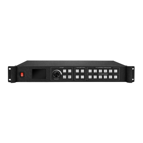
1、POWER-------------------------Equipment switch, OFF - power off, ON - power on
2、LCD--------Text display screen, display menus, parameters and other information
3、WIN-1-------------------------------------------------------------Screen 1 Selection Key
4、CV-1-------------------------------------------------------------------------CVBS1 button
5、CV-2-------------------------------------------------------------------------CVBS 2 button
6、number 3-----------------------------------------------------------number 3 key function
7、HDMI-------------------------------------------------------------HD Multimedia Channel
Key
8、PIP----------------------------------------------------------------double windows set key
9、MODE--------------------------------------------------------------------------call mode
10、MENU-----------------------------------------------------------------------------menu key
11、OK----Confirmation key, Click to enter the next interface when navigating mode
12、ADJUST---------------------------------------------The knob enlarges and decreases,
and the key is determined by pressing it.
13、WIN-2-----------------------------------------------------------window 2 Selection Key
14、VGA-1---------------------------------------------------------------VGA1 select key
15、VGA-2----------------------------------------------------------------VGA2 selection key
16、DVI---------------------------------------------------------------------DVI selection key
17、EXT. ----------------------------------------Extended Interface Signal Source Key
18、OUT----------------------------Switch between output black screen and normal; Note:
Blue screen is switched by knob.
19、PART--------------------------------------------------------------------part and full switch

7
20、Navigation keys-----------------User navigation mode, used as step size switch key
when adjusting data size
21、arrowhead tag----------------------------------------------------------------back key
back panel
○
1○
2○
3○
4○
5○
6○
7○
8○
9○
10 ○
11 ○
12
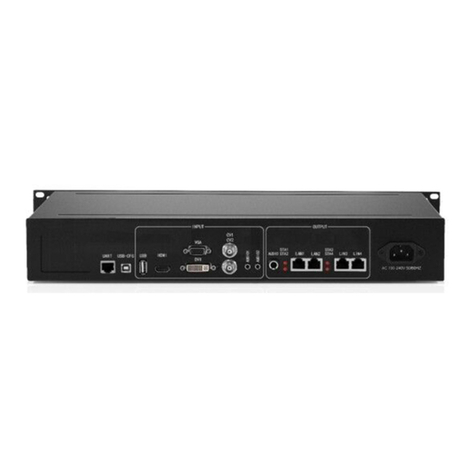
1、UART-------------------------------------Connecting PC Software through 9-pin
Serial Port to RJ45 Network Port
2、2、USB-CFG------------------Connecting PC Software through USB Square Port
3、Audio--------------------------------------Input and Output Interfaces of Audio
Signals
4、HDMI----------------------------------HDMI signal input interface such as notebook
5、DVI------------------------------------------DVI signal input interface such as desktop
6、VGA-1-----------------------------------VGA signal input interface such as notebook
7、DVI-LOOP-------------------------------------------Loop Out Interface of DVI Signal
8、VGA -2----------------------------------VGA signal input interface such as notebook
9、CV-1---------------------------------Compound signal input interface such as camera
10、CV-2---------------------------------Compound signal input interface such as camera
11、LAN1-8---------------------------------------------------------Network Port Output Port
12、power-----------------------------------------------------------------------220V Power

8
6. Wiring and Installation
Wiring diagram
Installation steps
1、As shown in the wiring, the DVI interface of the graphics card is connected with the
DVI-IN input port of the video processor.
2、Then connect the DVI interface of the graphics card with the DVI-IN input port of the
video processor and the DVI-OUT output port of the processor with the sending card as shown in
the figure.
3、Make sure the connection is correct and turn on the video processor.
Signal source
LED screen
Power cable
Ethernet net
USB control cable

9
VII、Equipment debugging
Wizard mode
This navigation is suitable for most cases. It is simple to set up. With the prompt, you can
gradually debug it to achieve the desired display effect. The processor automatically enters the
navigation mode when it is powered up.(or Click Enter Navigation Mode):
Note: Screen-adjusting navigation refers to debugging parameters of sending and receiving cards,
which requires box files; image navigation refers to debugging parameters of large screen image and
local display.
Click on "Screen-adjusting Wizard" and enter the password for setting the screen-adjusting:
Note: Set the password of "168", "666", "888" and "999" to adjust the screen.

10
Select whether to import the box file:
Note: The box files need to be imported into the equipment through the upper computer software.
The box files here refer to the parameters of the receiving card.
Set the number of rows/columns in the box:
Note: Number of rows/columns in the box refers to the number of horizontal/vertical receiving cards
used in the large screen.

11
Set the layout of keys according to the wire:
Note: Wire arrangement refers to the splicing mode between the wires.
Set up cabinet routing mode:
Note: Cabinet routing mode: Series mode between receiving cards should ensure that
the direction of the two lines is the same. Display whether normal:
Note: Normal click is displayed on the large screen; if not, go back to select the box file and reset it.

12
Set the number of large screen points:
Note: Set the number of large screen points, the number of large screen points is the size of the
whole screen.
Save settings:
Note: Some parameters of the control system are saved here.

13
Image navigation
Set the number of windows
Select the input source:
Note: Select the input signal source

14
full mode
Part mode
Whether local display is needed:
Note: This interface is to select whether it is necessary to intercept part of the image of the input
signal source and display it on the LED screen.
Ps-The most common way to do "partial display" is to display the full screen of the playback
window and switch to the panoramic display of the computer desktop at any time.
Among them, "location" - where to start intercepting; "size" - how big to intercept. The
interface is as follows:
Local display settings:

15
Save settings:
End of navigation:
The last step is to save the settings, in which mode one is automatically invoked after booting.
At this point, the setup of the processor is completed. In the process of using it, the signal can be
switched directly with the front panel. When "local display" is needed,click It can switch the
"local/panoramic" of the current signal source. If multiple modes are saved,use call different
mode
Thank you again for using our video processor. Please refer to the back section for other
details.

16
VIII、Control menu
Main menu
selection
custom
(I)screen
Navigation mode
(II)scaler
parameters
Horizontal position
0
Vertical position
0
Horizontal size
1920
Vertical size
1080
(III)part
Horizontal position
0
Vertical position
0
Horizontal size
0
Vertical size
0
(IV)Save
Mode 1
Mode 2
Mode 3
Mode 4
Mode 5
(V)Mode
Mode 1
Mode 2
Mode 3
Mode 4
Mode 5

17
(VI)more
(I)Language Settings
English
Chinese
Chinese
(II)factory
confirm
cancel
(III)support
Please contact the sales staff.
(IV)Planning tasks
On
Off
(V)switch
Cut
Effect
Time
(VI)VGA set
Horizontal position
Custom
Vertical position
Custom
Horizontal size
Custom
Vertical size
Custom
(VII)Picture Quality
Settings
brightness
50
Contrast
50
saturation
50
sharpening
14
Table of contents
Other Kystar Controllers manuals
Popular Controllers manuals by other brands

Smartharvest
Smartharvest SCCM20-100 owner's manual

Mitsubishi
Mitsubishi Q64AD-GH user manual

Lincoln
Lincoln CENTRO-MATIC SYSTEM SYSTEM SENTRY B Series Owner's/operator's manual

Exhausto
Exhausto EBC 10-P Product information

Emerson
Emerson NELSON CM-GP installation instructions

Patton
Patton SmartNode 5530 Series user manual