Instantel Minimate Pro4 User manual

The World’s Most Trusted Monitors — Vibration · Noise · Air Overpressure
www.instantel.com
www.instantel.com
Instruction Sheet
1Page
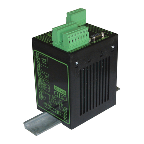
The Remote Alarm Controller is used to indicate when
the monitoring unit has exceeded its preset trigger levels
for a Warning signal and Alarm signal. The trigger level
settings can be congured based on the specic sensors
connected to the units. The secondary Alarm trigger
levels must be set higher than the Warning trigger levels.
The remote alarm outputs are isolated from the
seismograph using normal open relay contacts capable
of switching loads up to 2 amps and 24 volts DC.
The connections from the remote alarm output terminals
to the alarm device(s) can be extended over long
distances provided there is enough voltage available for
the alarm device.
Example: Pile driving operations often monitor
ground vibrations. The remote alarm can trigger
a Warning signal to notify an operator that the
activity has exceeded the preset trigger level and
appropriate action may be required. If the secondary
Alarm triggers, (when activity exceeds the dedicated
Vibration Alarm Trigger Level) the operator is notied
that operations should cease immediately.
Remote Alarm Controller
Tools and Materials Required
Micromate
• Micromate ISEE Base Unit . . . . . . . . . . . . . . . . . . . . . .(P/N: 721A2501) or
• Micromate DIN Base Unit . . . . . . . . . . . . . . . . . . . . . .(P/N: 721A2601) or
• Micromate Swedish Blasting Base Unit . . . . . . . . . . .(P/N: 721A3601) or
• Micromate Swedish Pile Driving Base Unit . . . . . . . .(P/N: 721A3801)
• Remote Alarm Controller . . . . . . . . . . . . . . . . . . . . . .(P/N: 721A0901)
• 10 m (33 ft) Extension Cable . . . . . . . . . . . . . . . .(P/N: 721A0803)
• 30 m (100 ft) Extension Cable . . . . . . . . . . . . . . .(P/N: 721A0801)
• 75 m (250 ft) Extension Cable . . . . . . . . . . . . . . .(P/N: 721A0802)
• Micromate Custom Extension Cable Kit . . . . . . . (P/N: 721A3201)
• External Alarm with Power Source (required, not supplied)
Minimate Pro
• Minimate Pro4 monitoring unit . . . . . . . . . . . . . . (P/N: 720A2301) or
• Minimate Pro6 monitoring unit . . . . . . . . . . . . . . (P/N: 720A2401)
• Remote Alarm Controller . . . . . . . . . . . . . . . . . . . . . . (P/N: 720A3901)
• 30 m (100 ft) Extension Cable . . . . . . . . . . . . . . .(P/N: 720A3301)
• 75 m (250 ft) Extension Cable . . . . . . . . . . . . . . .(P/N: 720A3302)
• Custom Length Extension Cable . . . . . . . . . . . (P/N: 301-000034-000)
• Custom Cable Connector Assembly . . . . . . . . . (P/N: 720A3305)
• Remote Alarm/Rs-232 Splitter Cable . . . . . . . . . .(P/N: 720A4001)
(Used when both a Remote Alarm Controler and a modem must be connected to the monitoring unit at the same time.)
• External Alarm with Power Source (required, not supplied)
Remote Alarm Controller for Micromate Monitoring Units
Remote Alarm Controller for Minimate Pro4/Pro6 Monitoring Units

2Page
Minimate Pro4 & Minimate Pro6 Alarm Setup
1. Press the Setup key to access the Main Menu.
2. Press the Down Arrow key to select the View/Edit Setup File menu option. Press the Enter key to enter this menu.
3. Press the Down Arrow key to select the Auxiliary I/O option. Press the Right Arrow key to enter the menu.
4. Press the Right Arrow key to change the Auxiliary I/O selection to Remote Alarm, as shown below:
(the bold text in brackets “[...]” represents the available options)
5. Determine how long you want the Warning Hold Time and Alarm Hold Time to sound. Enter a value using
the Right Arrow key to access their editing elds. Press the Up/Down Arrow keys to change their values. Jump
between the elds by using the Right or Left Arrow keys. Press the Enter key to Save the edits of each selection.
Note: The Warning Hold Time and Alarm Hold Time have a 300 second time limit (5 minutes). When set to 0,
the alarms remain indenitely and must be reset manually. The Remote Alarm Controller is only active once
the Start Monitor key is pressed on the unit.
6. Select the Alarm On option and press the Right Arrow key to scroll through which sensors will trigger an alarm.
Each key press will provide a new setting option.
7. Select the Vibration Level option and press the Right Arrow key to edit the values.
Note: The Minimate Pro6 monitoring unit using two geophones will offer two options to set the Vibration Alarm
Level, one for each geophone attached.
8. Press the Right Arrow key to move the cursor within the value eld, and the Up/Down Arrow key to
change the value.
9. Press the Enter key to Accept the new setting, or the Cancel key to exit the menu without saving the changes.
10. Select the Pressure Level option and press the Right Arrow key to edit the values.
Note: The Minimate Pro6 monitoring unit with a geophone and a microphone attached will provide options
to edit the levels for both sensors.
11. Press the Right Arrow key to move the cursor within the value eld, and the Up/Down Arrow key to
change the value.
12. Press the Enter key to Accept the new setting, or the Cancel key to exit the menu without saving the changes.
13. Within the Edit Current Setup menu, press the Enter key to Save the new Auxiliary I/O settings, or press the
Cancel key to Exit the menu without saving the changes.
Alarm Indicators
Warning – yellow LED with a pulsed sound from the internal warning device.
Alarm – red LED with a constant sound from the internal warning device.
External Devices – external alarm devices are optional.

3Page
How to Congure the Remote Alarm Controller Settings in THOR’s Unit Setup Menu
You can also congure the Warning/Alarm settings from within THOR software and send the Setup File to the
monitoring unit. (Only available for Micromate and Minimate Pro models)
1. Within THOR, click on the Unit Tab.
2. Click on the Unit Setup icon.
3. In the Unit Setup section, right-click and select New Unit Setup File.
4. Fill in the details and under Unit Type select either
Micromate,or Minimate Pro (you must also select the Setup Type: Compliance.)
5. Select Unit Setup section and under Auxiliary IO select Remote Alarm.
6. Fill in the appropriate Warning Hold Time in seconds and Alarm Hold Time in seconds.
7. Under Active Sensors click the Add Sensor button and select a sensor.
8. Check Enable Alarm, then dene the Alarm Level (in mm/s or in/s for Geophones, in dB(A) for Microphones)
Note: the alarm level cannot be lower then the dened trigger level.
9. Click on OK
10. Select the Monitoring unit connected to THOR and click Send to Unit(s) to send the Setup File to the Monitoring unit.
1
2
3
4
6
5
8
9
7
10

721U0901 Rev 03 - Product specications are subject to change
4Page
Toll Free (N.A.): 1.800.267.9111
Telephone: 1.613.592.4642
Email: [email protected]
www.instantel.com
Warranty
Instantel products come with a one-year warranty. Monitoring units and sensors will have the warranty extended for a second year if they are returned
to the Instantel factory for service and calibration within 30 days of the ‘Next Calibration’ date printed on the calibration label located on the product.
If within a period of one year from the date of shipment to a customer, the instrument fails to perform in accordance with Instantel’s published
specications and the operator’s manual, due to a defect in materials or workmanship, it will be repaired or replaced at Instantel’s option, free of
charge. This warranty is void if the equipment has been dismantled, altered or abused in any way. This warranty is nontransferable.
This warranty does not include any implied warranty of functionality for a particular purpose. Instantel assumes no responsibility for damages of any
description resulting from the operation or use of its products. Since it is impossible to anticipate all of the conditions under which its products will
be used either by themselves or in conjunction with other products, Instantel cannot accept responsibility for the results unless it has entered into a
contract for services which clearly dene such an extension of responsibility and liability.
Any shipments returned directly to Instantel Inc. must have our prior approval and all packages must display the Return of Material Authorization
(RMA) number issued by Instantel. Shipping charges to Instantel’s plant will be paid by the customer and those for return to the customer will be
paid by Instantel.
To protect your warranty, you must complete and return a Warranty Registration Certicate, or complete the online Warranty Registration Form,
within ten days of purchase. Products will be assumed out of warranty if there is no warranty card on le at Instantel. Retain this portion and the
proof of purchase for your records.
EC Warning
This is a Class A product. In a domestic environment this product may cause radio interference in which case the user may be required to take
adequate measures.
Physical Installation
1. Connect the Remote Alarm Controller to the Auxilliary connector on the monitoring unit. To increase the distance
between the two devices make use of the appropriate extension cable as referenced by unit and part number in
the previous table.
2. The output available on the terminal block is only a switch. You must supply external power to drive the load.
When using an external warning device, the common terminal is the ground or minus side of the external
load-power source combination. Normally, one side of the external load connects to the positive side of the
power supply. The negative side of the power supply connects to the common terminal.
Micromate Alarm Setup
1. Press the Setup key to access the Setup Options.
2. Press the Checkmark key to enter the View/Edit Current Setup menu option.
3. Press the Down Arrow key to select the Auxiliary I/O option.
4. Press the Checkmark key to enter the menu.
5. Press the Down Arrow key to select Auxiliary Mode.
6. Scroll through the available options using the Checkmark key until Remote Alarm is selected.
7. Press the Down Arrow key to select Alarm On and enter the menu using the Checkmark key.
8. Change the values using the Down Arrow and Checkmark keys.
9. Press Cancel to exit and Save any changes.
10. Use the Down Arrow key to select the Warning Hold and Alarm Hold options.
11. Change their values using the Checkmark key to scroll through the available settings.
12. Press the Cancel key to exit, validate the changes by saving them with the Checkmark key.
13. Select Save to Current File and then Overwrite File, or Save to New File and create a new le name
using the touchscreen keypad.
14. Press Cancel to exit and return to the Homescreen.
This manual suits for next models
1
Table of contents
Popular Controllers manuals by other brands
Bodine
Bodine Quality IN Motion 0810 Instructions for installation and operation

gefran
gefran SIEIDrive ADV200-x-6 Series Quick start up guide
Keating Of Chicago
Keating Of Chicago Meridian 10 manual
FasTest
FasTest G346 BH Series operating instructions
YASKAWA
YASKAWA SI-EP3 Technical manual
Knoll
Knoll VC100PM installation guide
