manuals.online logo
Brands
  1. Home
  2. •
  3. Brands
  4. •
  5. Ingersoll-Rand
  6. •
  7. Controllers
  8. •
  9. Ingersoll-Rand ARO 2752 Series User manual

Ingersoll-Rand ARO 2752 Series User manual

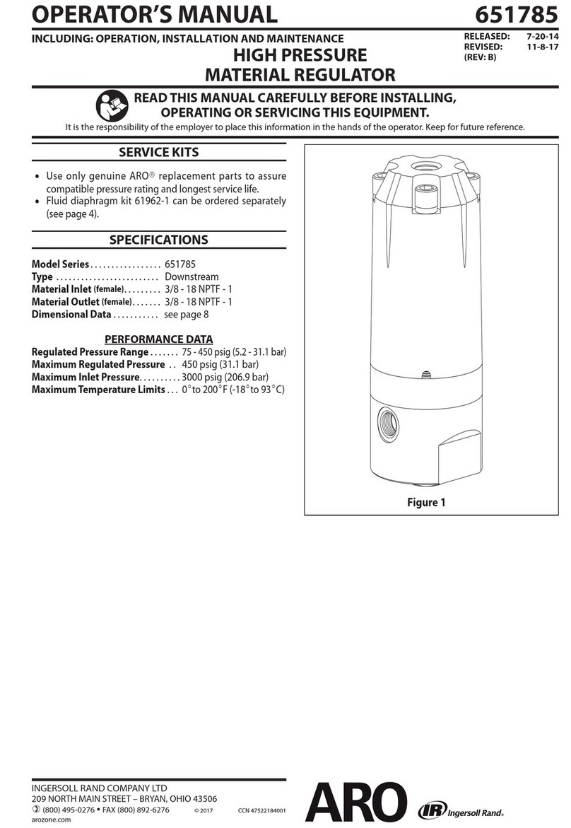
OPERATOR’S MANUAL 2752X-X
INCLUDING: OPERATION, INSTALLATION AND MAINTENANCE. RELEASED: 11-13-74
REVISED: 7-26-18
(REV: F)
FLUID REGULATOR
READ THIS MANUAL CAREFULLY BEFORE INSTALLING,
OPERATING OR SERVICING THIS EQUIPMENT.
It is the responsibility of the employer to place this information in the hands of the operator. Keep for future reference.
The original language of this manual is English.
INGERSOLL RAND COMPANY LTD
209 NORTH MAIN STREET – BRYAN, OHIO 43506
(800) 495-0276 FAX (800) 892-6276 © 2018 CCN 99565392
arozone.com
STANDARD CAPACITY
STAINLESS STEEL
DOWNSTREAM TYPE
MAXIMUM INLET PRESSURE 750 PSI (51.7 BAR)
1/4” INLET/OUTLET
THIS MANUAL COVERS THE FOLLOWING MODELS
5-125 PSI WORKING RANGE 0-50 PSI WORKING RANGE 10-250 PSI WORKING RANGE 0-30 PSI WORKING RANGE
27520-000 27520-100 27520-200 27520-400
27521-000 27521-100 27521-200 27521-400
27522-000 27522-100 27522-200
27521-300
SERVICE KITS
Use only genuine ARO replacement parts to assure compati-
ble pressure rating.
OPERATION
To adjust back pressure, turn Y23-72-B screw clockwise with
Y106-105 allen wrench which is furnished with unit. To de-
crease pressure, turn Y23-72-B screw counter clockwise. (Does
not apply to Model 27521-300.) To adjust pressure on Model
27521-300, regulate air pressure to back side of diaphragms
using auxiliary port on 104135 cap.
SERVICE HINTS
yIf outlet pressure rises or creeps, check (D) seat assembly
and (F) ball for foreign material. If (D) seat assembly and
(F) ball appear to be worn or eroded, they should be re-
placed. (See Figure 2).
yIf material is leaking through bleed hole in 29919 housing
and nut assembly, replace 29000 and 90860 diaphragms.
(Does not apply to model 27521-300). FIGURE 1
Page 2 of 4 2752X-X (en)
OPERATING AND SAFETY PRECAUTIONS
yRead and heed all Warnings, Cautions, and Safety Precau-
tions before operating this pump.
yUse only genuine ARO replacement parts to assure compat-
ible pressure rating and longest service life.
WARNING
MISAPPLICATION HAZARD. DO NOT USE A REG-
ULATOR WHERE THE FLUID INLET PRESSURE IS TOO HIGH
FOR THE DESIGNED OPERATING RANGE.
WARNING
HIGH PRESSURE DEVICE. IMPROPER USAGE OF
THIS EQUIPMENT COULD RESULT IN SERIOUS INJURY. The
possibility of injection into the esh is a potential hazard.
Wear approved safety glasses or face shield any other
equipment as needed to prevent injury. Never allow any
part of the human body to come in front of or in direct con-
tact with the material outlet, the tip, or the material outlet
of the dispensing device. An injection injury can be serious.
If an injection accident should occur, it is very important
that you contact a qualied physician for immediate treat-
ment.
WARNING
COMPONENT RUPTURE. DO NOT OPERATE REG-
ULATOR AT AN INLET PRESSURE GREATER THAN SPECIFIED.
To avoid possible damage or personal injury do not operate
this unit at pressure higher than the stated operating range
as appears on the model plate.
WARNING
HAZARDOUS AIR PRESSURE. CAN RESULT IN
SERIOUS INJURY. DO NOT SERVICE OR CLEAN PUMP, HOSES
OR DISPENSING VALVE WHILE THE SYSTEM IS PRESSURIZED.
First disconnect air line, then relieve pressure from the sys-
tem by opening dispensing valve or device and/or carefully
and slowly loosening and removing outlet hose or piping
from pump.
WARNING
DISASSEMBLY HAZARD. DO NOT DISASSEMBLE
THIS REGULATOR WHEN IT IS UNDER PRESSURE. RELIEVE
ALL MATERIAL PRESSURE IN THE PUMPING SYSTEM BEFORE
ATTEMPTING SERVICE OR DISASSEMBLY PROCEDURES.
Disconnect air lines and carefully bleed off of the system.
Be certain the system is not maintaining pressure due to a
material restriction in the hose line, dispensing de- vice, or
the spray or extrusion tip. Failure to relieve pressure both
up stream and downstream may result in an injury upon
disassembly.
WARNING
BONNET REMOVAL HAZARD. DO NOT ATTEMPT
TO REMOVE THE BONNET RETAINING BOLTS WITHOUT FIRST
RELIEVING THE TENSION ON THE MAIN SPRING. Failure to
relieve tension could result in an accident upon disassem-
bly.
WARNING
BPREVENT FIRES. KEEP SOLVENTS AWAY FROM
HEAT, SPARKS, OR OPEN FLAME. Keep containers closed
when not in use. When pumping, flushing or recirculating
volatile solvents be certain the area is adequately ventilat-
ed.
CAUTION
FLUSH SUPPLY LINE. Before installing uid reg-
ulator blow the supply lines clear and ush to remove con-
taminates.
DISASSEMBLY
1. Unscrew the Y154-54-C and Y154-56-C screws from the Y22-
10-C nuts.
2. Lift the 29919 housing and nut assembly from the 29446 base.
3. Remove the 29273 spring cap and (B) spring. (For Model
27521-300, unscrew the Y154-54-C and Y154-56-C screws from
the 104135 cap. Also remove Y14-10-C lockwashers.)
4. The 29000 and 90860 diaphragms are now accessible. Unscrew
(D) seat assembly from the 29446 base. This provides access to
(D) seat assembly and 29449 seal and 29451 spring.
REASSEMBLY
1. Place 29451 spring in 29446. Set (F) ball on top of spring. Use
new 29449 seal, place it on 29446 base.
2. Screw (D) seat assembly into 29446 base and tighten to 20 ft.
lbs.
3. To assemble diaphragm place 29000 and 90860 diaphragms
together. Place 90860 diaphragm next to the hex over the
threaded end of the (E) pushrod.
4. Apply Loctite 242 to threads on (E) pushrod. Screw (E) pushrod
into (C) back-up plate and tighten, making sure all holes in
the diaphragms align. Align holes in diaphragms with holes in
base.
5. Place 29919 housing and nut assembly on the 29000 dia-
phragm.
6. Insert Y154-54-C and Y154-56-C screws through the holes in
the 29919 housing and nut assembly.
7. Place Y22-10-C nuts on screws and tighten. (For Model 27521-
300, assemble 104135 cap to 29446 base using Y154-54-C and
Y154-56-C screws. Also include Y14-10-C Lockwashers.
2752X-X (en) Page 3 of 4
PARTS LIST / 27520-XXX, 27521-XXX AND 27522-XXX
+
Y154-54-C (4)
CAP SCREW
Y154-56-C (2)
CAP SCREW
Y154-56-C (2)
CAP SCREW
Y14-10-C (6)
LOCKWASHER
Y154-54-C (4)
CAP SCREW
29919 SPRING AND NUT
HOUSING ASM
Y23-72-B SET
SCREW
104135
CAP
Y22-10-C (6)
NUT
"B"
"C"
"D"
"E"
"F"
"A"
OUTLET
OUTLET
29451 SPRING
29449 SEAL
29000 DIAPHRAGM
29273 SPRING
MODEL 27521-300 ONLY
CAP
TORQUE TO 45 5 IN. LBS
NOTE: INCLUDED BUT NOT SHOWN
Y106-105 ALLEN WRENCH INLET
29446 BASE
FIGURE 2
90860 DIAPHRAGM
(TORQUE TO 10 + 2 FT LBS)
PARTS LIST
MODEL # ‘‘A” PORT ‘B” SPRING ‘‘C” PLATE ‘‘D” SEAT ‘‘E” ROD ‘‘F” BALL BALL MATL.
27520–000 1/4 N.P.T.F. 29002 (5–125) 29001 29981 29983 29254 T’CARBIDE
27520–100 1/4 N.P.T.F. 29119 (0–50) 29001 29981 29983 29254 T’CARBIDE
27520–200 1/4 N.P.T.F. 29120 (10–250) 29155 29981 29983 29254 T’CARBIDE
27520–400 1/4 N.P.T.F. 93998 (0–10) 29001 29981 29983 29254 T’CARBIDE
27521–000 1/4 N.P.T.F. 29002 (5–125) 29001 29982 29447 Y16–108 S’STL
27521–100 1/4 N.P.T.F. 29119 (0–50) 29001 29982 29447 Y16–108 S’STL
27521–200 1/4 N.P.T.F. 29120 (10–250) 29155 29982 29447 Y16–108 S’STL
27521–300 1/4 N.P.T.F. –––––––––––– 29001 29982 29447 Y16–108 S’STL
27521–400 1/4 N.P.T.F. 93998 (0–10) 29001 29982 29447 Y16–108 S’STL
27522–000 1/4 N.P.T.F. 29002 (5–125) 29001 29982 29447 29253 RUBBER
27522–100 1/4 N.P.T.F. 29119 (0–50) 29001 29982 29447 29253 RUBBER
27522–200 1/4 N.P.T.F. 29120 (10–250) 29155 29982 29447 29253 RUBBER
Page 4 of 4 2752X-X (en)
PN 97999-674
1.063”
27.00 mm
5.338”
135.58 mm
3.062”
77.92 mm
3.500”
88.90 mm
DIMENSIONAL DATA
FIGURE 3

This manual suits for next models

12

Other Ingersoll-Rand Controllers manuals

Ingersoll-Rand ESCB10 Manual

Ingersoll-Rand

Ingersoll-Rand ESCB10 Manual

Ingersoll-Rand X8I User manual

Ingersoll-Rand

Ingersoll-Rand X8I User manual

Ingersoll-Rand EC24N User manual

Ingersoll-Rand

Ingersoll-Rand EC24N User manual

Ingersoll-Rand SE Installation guide

Ingersoll-Rand

Ingersoll-Rand SE Installation guide

Ingersoll-Rand ST150 Series Setup guide

Ingersoll-Rand

Ingersoll-Rand ST150 Series Setup guide

Ingersoll-Rand SS815 Series Setup guide

Ingersoll-Rand

Ingersoll-Rand SS815 Series Setup guide

Ingersoll-Rand 302 SERIES User manual

Ingersoll-Rand

Ingersoll-Rand 302 SERIES User manual

Ingersoll-Rand ESCB20 User manual

Ingersoll-Rand

Ingersoll-Rand ESCB20 User manual

Ingersoll-Rand X4I User manual

Ingersoll-Rand

Ingersoll-Rand X4I User manual

Ingersoll-Rand ReliaTel User manual

Ingersoll-Rand

Ingersoll-Rand ReliaTel User manual

Ingersoll-Rand ST600-13-31 Setup guide

Ingersoll-Rand

Ingersoll-Rand ST600-13-31 Setup guide

Ingersoll-Rand 150T P Series Setup guide

Ingersoll-Rand

Ingersoll-Rand 150T P Series Setup guide

Ingersoll-Rand Insight IC Series User manual

Ingersoll-Rand

Ingersoll-Rand Insight IC Series User manual

Ingersoll-Rand ST400 Series Setup guide

Ingersoll-Rand

Ingersoll-Rand ST400 Series Setup guide

Ingersoll-Rand ST400 Series User manual

Ingersoll-Rand

Ingersoll-Rand ST400 Series User manual

Ingersoll-Rand Intellisys Remote Interface User manual

Ingersoll-Rand

Ingersoll-Rand Intellisys Remote Interface User manual

Ingersoll-Rand EC24N User manual

Ingersoll-Rand

Ingersoll-Rand EC24N User manual

Ingersoll-Rand EC24E User manual

Ingersoll-Rand

Ingersoll-Rand EC24E User manual

Ingersoll-Rand Nirvana SGNe V2.5 User manual

Ingersoll-Rand

Ingersoll-Rand Nirvana SGNe V2.5 User manual

Ingersoll-Rand EC34ES-1 User manual

Ingersoll-Rand

Ingersoll-Rand EC34ES-1 User manual

Ingersoll-Rand Xe-50 User manual

Ingersoll-Rand

Ingersoll-Rand Xe-50 User manual

Ingersoll-Rand ZGB015-KIT User manual

Ingersoll-Rand

Ingersoll-Rand ZGB015-KIT User manual

Ingersoll-Rand ST900 Series Setup guide

Ingersoll-Rand

Ingersoll-Rand ST900 Series Setup guide

Ingersoll-Rand ST1000M Series Setup guide

Ingersoll-Rand

Ingersoll-Rand ST1000M Series Setup guide

Popular Controllers manuals by other brands

OptoSigma SRC-101 instruction manual

OptoSigma

OptoSigma SRC-101 instruction manual

HDL MPR0310.40 quick start guide

HDL

HDL MPR0310.40 quick start guide

Graham Vari Speed S1000 instruction manual

Graham

Graham Vari Speed S1000 instruction manual

TCS ISW6031-0145 quick start guide

TCS

TCS ISW6031-0145 quick start guide

JJC WR-100 Instruction

JJC

JJC WR-100 Instruction

Vadsbo LCC60 installation instructions

Vadsbo

Vadsbo LCC60 installation instructions

Seiko PS-110 operating manual

Seiko

Seiko PS-110 operating manual

GOK ODR Assembly and operating manual

GOK

GOK ODR Assembly and operating manual

SPL 2489 user manual

SPL

SPL 2489 user manual

MidNite Solar The Kid quick start guide

MidNite Solar

MidNite Solar The Kid quick start guide

Vacon 100X series Applications manual

Vacon

Vacon 100X series Applications manual

Lindab Regula Combi Installation

Lindab

Lindab Regula Combi Installation

Full Gauge Controls MT-530E Super manual

Full Gauge Controls

Full Gauge Controls MT-530E Super manual

Industrial Indexing Systems MSC-250 user guide

Industrial Indexing Systems

Industrial Indexing Systems MSC-250 user guide

Carlisle MS Elite 461959 B Series Service manual

Carlisle

Carlisle MS Elite 461959 B Series Service manual

nord NORDAC BASE SK 1 0E Series quick start

nord

nord NORDAC BASE SK 1 0E Series quick start

Graco PRECISION MIX 949-999 manual

Graco

Graco PRECISION MIX 949-999 manual

Calpeda IDROMAT 3 Original operating instructions

Calpeda

Calpeda IDROMAT 3 Original operating instructions

manuals.online logo
manuals.online logoBrands
  • About & Mission
  • Contact us
  • Privacy Policy
  • Terms and Conditions

Copyright 2025 Manuals.Online. All Rights Reserved.