L.R. Baggs Element Active System User manual

Element Active System
Installation Manual
Jack tip recessed inside of strap-ring
Jack tip ush with strap-ring
PACKAGE CONTENTS
One Element Active System with undersaddle pickup, endpin preamp w/volume control
attached.
One battery bag
Three self-stick wire clips
OVERVIEW AND CAUTIONS
The Element Active System combines the Element undersaddle pickup with a pre-contoured,
all-discrete Class A endpin preamp. A soundhole mounted volume pot gives you additional
control and versatility without requiring any other modications to your instrument. The
Element Active is designed to interface with just about anything you plug into, but best
results will be realized through a high-quality, full-range PA. Plugging in and unplugging
the cord from your guitar will turn the preamp on and o.
We recommend that this pickup system be installed by a professional dealer/installer. We
do not provide installation advice or support for home or hobbyist installations.
Installers: Please read the instructions carefully before proceeding. We will not be
responsible for any damage to the guitar or personal injury from installation, improper
installation, use or misuse of the product.
STRAPJACK/PREAMP INSTALLATION
If your guitar already has a half inch hole in the tail block, proceed to the installation.
Drilling the strapjack hole: This jack requires a clean, half inch hole in the tail block of
the instrument. The easiest way to drill this hole accurately and eectively is to use a half
inch “step” drill-bit, available at any hardware store. Other options are to use a “Forstner
Bit”, or a “Brad-point bit”.
CAUTION: DO NOT USE A SPADE BIT OR STANDARD DRILL BIT FOR THIS!
Begin by placing a piece of masking tape over the area to be drilled (generally, in the center
of the tail block). This is to protect the guitar’s nish. Drill a pilot hole approximately 3/16”
dia. Now you can nish up using the step-drill. Place the tip of the step-drill in the pilot
hole, line up the drill as straight as you can, and proceed to drill until you’ve gone all the
way through the tail block.
Installing the strapjack: Remove the strap ring, retaining nut, and one washer from the
end of the jack. There will still be one at washer, one star-locking washer, and one nut
remaining on the threaded barrel of the jack.
Adjust this nut and washers to a depth on the barrel that will allow approximately 90% of
the smaller threaded portion of the jack to extend beyond the tail block outside the guitar.
Bring the jack down through the soundhole into the guitar and insert it into the pre-drilled
hole in the tail-block to check the adjustment. There should be a couple of threads
remaining within the hole.
With the jack in place, lay the remaining washer over the threads and attach the external
retaining nut until it’s tight. Finish by attaching the strap ring.
Upon completion, the small threaded section of the jack should be ush or near ush with
the end of the strap ring. If the threaded section is recessed too far, the plug will not make
electrical contact with the jack! Therefore, be sure to adjust this until it is right.

PICKUP INSTALLATION
Notes: For optimum performance of the Element pickup, the bridge slot must have a
perfectly at surface, free from high spots and loose debris. The slot depth should be
3/16” (.187”) or deeper. The commonly known 50/50 rule applies: “The amount of saddle
visible above the bridge surface (with pickup installed) should be no greater than the
amount of saddle in the slot beneath the bridge surface”.
The bottom surface of the saddle must also be perfectly at to establish even contact
along the pickup between the saddle and the slot! This can be accomplished by sanding
against a machined surface using ne grit sandpaper.
Installation: Remove the strings from the guitar. For guitars having a pickup installed for
the rst time you will need to compensate for the thickness of the pickup by removing
.030” from the overall saddle height. One simple method of accomplishing this is as
follows: Using a freshly sharpened pencil, scribe a line along the front edge of the saddle
where it extends above the bridge, see Fig 1.
This line will be used later as a guide when removing material from the bottom of the
saddle. (Details to follow)
Now remove the saddle to drill a hole for the pickup. Use a drill bit that is the same size as
the width of the saddle slot, generally between 3/32” and 1/8”.
Just before you drill, inspect the underside of the bridge inside the guitar and note the
position of the braces in relation to the saddle slot. It’s helpful to use the bridge pin holes
for visual reference. You may drill the hole at either end of the slot but be sure to position
the hole at the extreme end of the slot and drill at an angle if possible, as seen in Fig 3A.
Last, choose the side of the slot which allows you to drill without damaging a brace as you
penetrate the top, then proceed to drill. Remove any splintering left from the bit with a
small le or razor blade, then blow out the slot with compressed air and check for
remaining debris.
Feed the pickup into the slot from inside the guitar. Inserting a toothpick into the hole from
the outside of the guitar helps with nding the hole on the inside. There is a black dot on the
end of the Element pickup, which should be facing up when the pickup is laid in place.
Important: The t of the saddle is among the most crucial factors of this installation. The
saddle should t loosely enough in the slot that it can be pulled out easily (using only
your ngertips) with just the slightest amount of drag. If the saddle binds at all in the slot,
sand it down just a bit against a at surface with 220 to 320 grit sandpaper until it goes in
and out with ease. A saddle that binds on the walls of the slot won’t be able to make
thorough contact with the pickup and will cause the pickup to malfunction. A saddle
which is excessively loose will lean forward under pressure, creating uneven contact on
the pickup, Fig 2A, which will most likely result in poor performance.
The best remedy for a very loose saddle is to make a new properly tting saddle, Fig 2B.
However, you can also shim the saddle thickness with tape until it ts correctly or even
sand an intentional tilt into the saddle’s bottom surface so that when it leans forward it
makes even contact on the pickup, Fig 2C.
Compensating for the thickness of the pickup: Lay the saddle over the pickup in the
slot and observe the scribed line from Fig 1. The distance between the bridge top and the
line is the amount of material you’ll need to remove from the bottom of the saddle. Sand
the bottom surface of the saddle on a belt sander until the scribed line is just above the
bridge top.
A belt sander is not capable of creating a truly at surface; therefore, it is necessary to
complete sanding the bottom of the saddle by hand. It is best to do this against a
machined at surface with ne sandpaper. Use a straight edge with a strong light source
to inspect the atness of your saddle.
When nished, make sure the pickup extends all the way to the far end of the slot, place
the saddle on top of it and temporarily secure it with a piece of tape. Secure the pickup
wire with a wire clip (provided) about 1 ½” from the exit hole on the edge of the bridge
plate, with a 1 to 2 inch service loop, Fig 3A & 3B.
Fig. 1
Fig. 2A
Fig. 2B
Fig. 2C
Before
After
Fig. 3A – Back view
Fig. 3B – Side view
Secure the other loose wires with the rest of the wire clips provided. Now re-string the
guitar, plug into your amp or PA, and test the pickup. Pay close attention to string balance.
String balance issues are unfortunately somewhat common among undersaddle pickups.
They are frustrating for both installer and player and can be caused by a variety of things
ranging from saddle t, saddle material, particular guitar resonances, saddle slot inconsis-
tencies, bridge problems, among others.
Concurrently, the x to string balance issues is also various and not always what you would
expect. If you have completed the installation according to these instructions and are
experiencing string balance issues, our best recommendation is for you to contact our
customer service department for assistance.
FINISHING THE INSTALLATION
Volume wheel placement: Stick the double-sided adhesive to an easily accessible spot
along the inside of the soundhole. It is most commonly positioned at the top of the
soundhole, above the strings when playing.
Battery bag placement: The battery bag can be located in a number of areas. We
recommend sticking it to the neck block if it is accessible, as it is the most able to handle
the weight of the battery, as well as oering easy access for quick battery changes. If you
choose another location, we recommend you nd an area on the side or back near a
brace for stability and ease of access.
OTHER APPLICATIONS
Passive auxiliary channel: The Element Active provides an option on its circuit board for
adding a second passive pickup to your signal in a stereo conguration. Magnetic pickups
work best for this scenario. We recommend you do not use high impedance pickups for
this application.
Soldering a second pickup: Solder the hot lead to positive and the ground lead to
negative of the auxiliary passive input. See diagram.
You’ll need to run your signal down a stereo cable to a stereo input or use a stereo “Y” cable
to two separate inputs. The 2nd pickup will be on the “ring” contact of the stereo plug.
Adding a mini-mic: It is possible to add a mini-mic in the same way the second pickup is
connected. Keep in mind, however, that it is a passive channel and you will need to provide
phantom power for the mic. The mic will be on the “ring” contact of the stereo plug.
Element Active input
Aux passive input
Table of contents
Other L.R. Baggs Accessories For Musical Instruments manuals

L.R. Baggs
L.R. Baggs ANTHEM-SL User manual

L.R. Baggs
L.R. Baggs M1 ACTIVE Guide

L.R. Baggs
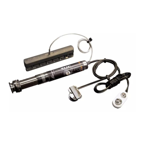
L.R. Baggs iBeam Active System Guide

L.R. Baggs
L.R. Baggs Dual Source Guide

L.R. Baggs
L.R. Baggs LB6 Series Guide

L.R. Baggs
L.R. Baggs Anthem System User manual

L.R. Baggs
L.R. Baggs M1 Guide

L.R. Baggs
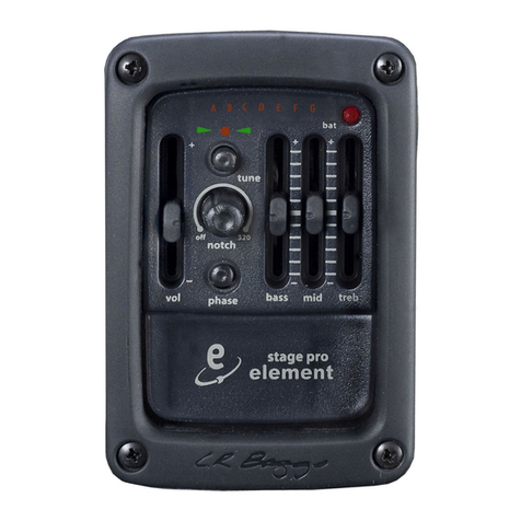
L.R. Baggs Stagepro Element User manual