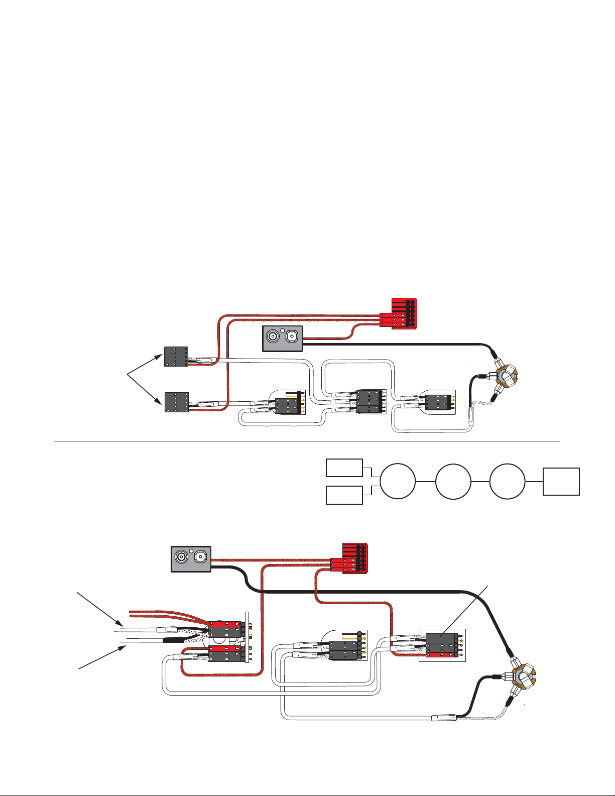
Diagram #2
One Pickup
One Volume
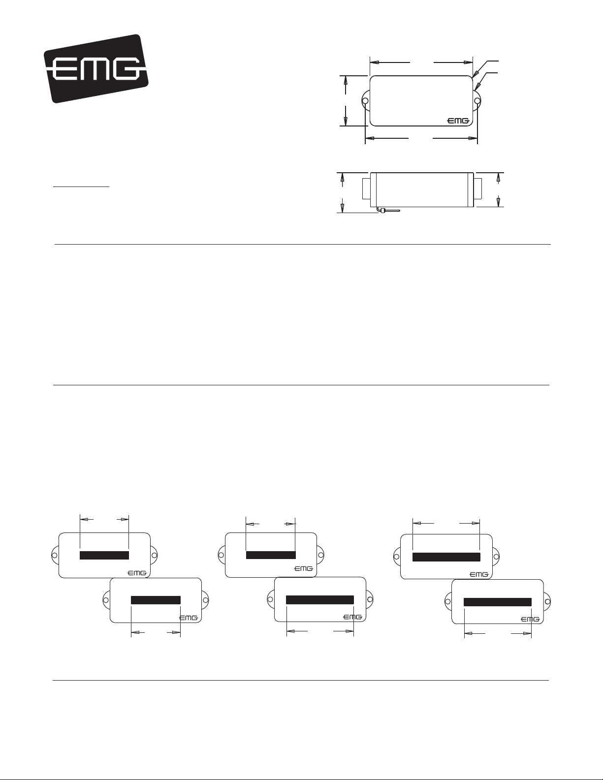
E/A SIDE
B/E/A SIDE
D/G SIDE
D/G/C SIDE
General Notes:
Every attempt has been made to make this a solderless installation.
There are some instances where this is not possible;
1) If your instrument uses the long panel output jack and you had passive pickups
you will need a new stereo output jack, the Switchcraft 152B is recommended.
Soldering to the new jack will be required, see page 4.
2) Power Supply tips are on page 4. If your instrument has a battery holder,
you are installing this pickup with an older EMG, or you want to supply your
instrument with +18 Volts, see page 4 for tips to avoid soldering.
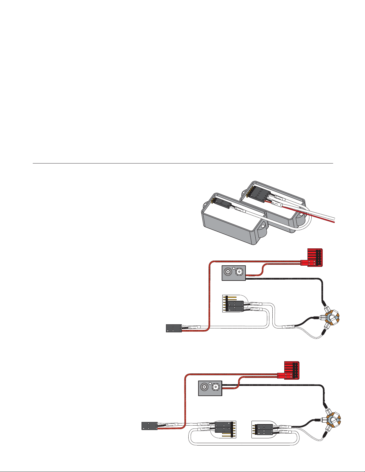
If you are installing only one pickup use the instructions on this page.
If you are installing two pickups go to page 3 and begin there.
Installation Instructions:
EMG Models: EMG-P, PA-V1, PA-V2, P-CS (4-STRING)
P5, P5-CS (5-STRING)
P6, P6-CS (6-STRING)
P, PA Page 2
IMPORTANT INSTALLATION NOTES:
1) Only one 9-Volt battery is required to power the pickups and any
accessories such as the EXB, BTC, B125 Blend, and BQ Controls.
Use an Alkaline or Lithium battery for longest life.
2) The Volume and Tone controls included with this EMG System are
25K Ohm. This value is required for the system to work correctly.
3) A stereo output jack (12B) is included with the EMG Pickups;
it grounds the black battery wire to turn on the pickups when
the plug is inserted into the jack. If you are replacing passive
pickups, make sure to use the jack included. If your guitar has a
long panel jack (see Page 4) make sure it is a stereo type, a
Switchcraft 152B is recommended.
4) When installing EMG Active Pickups, DO NOT connect the bridge
ground wire. This wire is usually soldered to a volume or tone
control casing and goes to the bridge. This wire grounds the
strings and uses them and your body as a shield against hum and
buzz. It also creates a shock hazard.
EMG Pickups are shielded internally and DO NOT require string
grounding. This greatly reduces the possibility of reverse
polarity shock from microphones and other equipment.
5) EMG Active Pickups have very little magnetism compared to
passive pickups. We recommend you adjust the pickups as
close to the strings as possible. Sustain and string movement
will not be inhibited by close adjustment.
6) If your installation is different from the diagrams in these
instructions or you need additional diagrams visit our website:
emgpickups.com for a complete listing of available diagrams.
7) SPECIAL NOTE:
The diagrams shown are for EMG Active Pickups.
All diagrams show the Red Wire coming from the pickups
connected to the battery. If you are installing EMG-HZ
Passive Pickups refer to their diagrams. The Red Wire of
the HZ Pickup is NOT for battery power, it is a coil wire.
MASTER
VOLUME
FROM PICKUP
OUTPUT
T
R
S
BATTERY
NEG (-)
RED
RED
BATTERY
BUSS
OUTPUT CABLE
- 9V +
Diagram #1
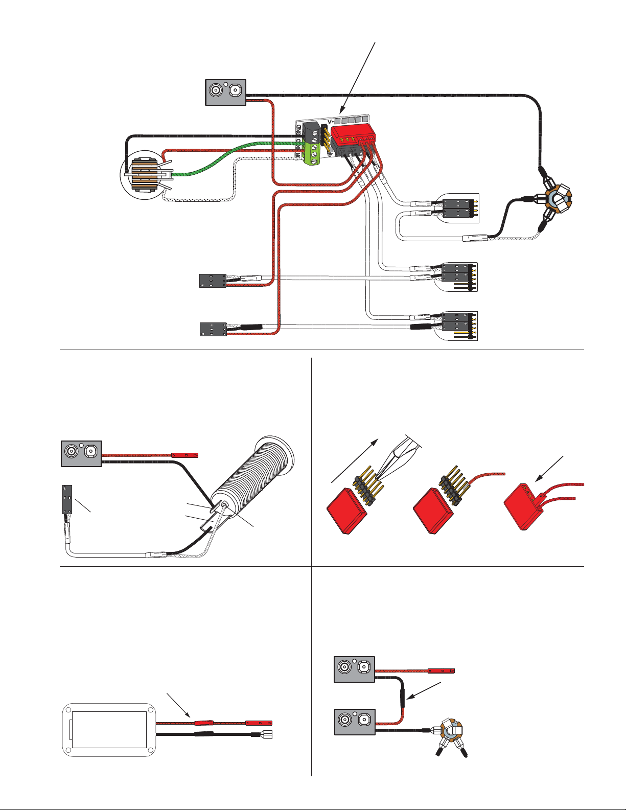
Diagram #3
One Pickup
One Volume
One Tone
OUTPUT
T
R
S
PASSIVE
TONE
FROM PICKUP
BATTERY
NEG (-)
RED
RED
BATTERY
BUSS
OUTPUT CABLE
MASTER
VOLUME
- 9V +
Installation (One Pickup Guitars):
1) Plug the pickup cable onto the EMG Pickup header as shown
in Diagram #1 and route the cable to the control cavity.
If the cable is too long, wind up the excess and keep it
under the pickup if possible.
Master Volume control only
2) Refer to Diagram #2. Plug both the Pickup cable and the output
cable onto the Volume control as shown, then go to step 4.
Master Volume and Tone control
3) Refer to diagram #3. Plug the Pickup cable onto the Volume
control as shown. Plug a coax cable from the Volume control
to the Tone control. Plug the output cable onto the tone
control as shown.
4) Connect the wires of the output cable to the output jack by
pushing the connectors on as shown.
WHITE wire to the TIP (T) contact,
BLACK wire to the SLEEVE (S) contact
BLACK Battery Negative wire to the RING (R) contact.
5) Using the battery buss, insert the RED wire of the pickup,
and the battery RED wire. Extra pins can be used for
EMG Accessories.
6) Put the battery in the insulating foam piece provided
and place it securely in the control cavity.
We suggest that you plug in the instrument and
test it before closing the control cavity.