L.T. Rich Products Z-Spray JR36R User manual

OWNERS MANUAL
JR36R / ZS-3620R Z-Spray


TABLE OF CONTENTS
\
SECTION 1 TO THE OWNER PAGE
1.1 Read this manual entirely BEFORE operating the Z-Spray………………………..…..1
1.2 Product / Warranty Registration…………….…………………………………..……...1
1.3 L T Rich Products Warranty……………………………………………………………1
1.4 Component Manufactures’ Warranties…………………………………………..……..2
1.5 Conditions Which Void Warranty……………………………………………….……..2
1.6 Warranty Exceptions……………………………………………………………..……..2
SECTION 2 SAFETY INFORMATION PAGE
2.1 About this manual………………………………………………………………...….2-3
2.2 Safety guards and covers……………………………………………………………….3
2.3 Operational Safety Rules……………………………………………………………….3
2.4 Maintenance Safety Rules…………………………………………………………....3-4
2.5 Storage Safety Rules……………………………………………………………….…...4
SECTION 3 MAINTENANCE PAGE
3.1 Engine Maintenance……………………………………………………………………..4
3.2 Hydraulic System Maintenance…………………………………………….………....4-5
3.3 Traction Unit Maintenance……………………………………………………………5-6
3.4 Spray System Maintenance………………………………………………………….......6
3.5 Spreader System Maintenance……………………………………………………...…6-7
Maintenance Chart………………………………………………………………..……24
SECTION 4 Z-SPRAY OPERATIONS PAGE
4.1 Operations………………………………………………………………………………..7
4.2 Spraying operations..……………………………………………………………….….7-9
4.3 Spray Calibration/Tip Chart/Liquid Quantities……………….……………..…....….9-11
4.4 Spreader Operation……………………………………………………………………..12
4.5 Spreader Calibration/Layout………………………….…………………………..…12-13
SECTION 5 PARTS PAGE
5.1 Parts Breakdowns/Part Numbers……..……………...……..….…………….……….13-18
SECTION 6 TROUBLESHOOTING PAGE
6.1 Troubleshooting………………………………………………………………………19-21
SECTION 7 RACK SYSTEM WEIGHT LIMITS/LOADING PAGE
7.1 Loading procedures, weights limits and dimensions…………………………………….22
7.2 Warranty Card………………………………………………………………………..….23

SECTION 1 TO THE OWNER
1.1 Read this manual entirely BEFORE operating the Z-Spray
The information presented herein will prepare you to operate the L.T. Rich Z-Spray in a
safe and knowledgeable manner. Operating the Z-Spray in a proper manner will provide a
safer working environment, create more efficient results and promote higher quality.
Keep this manual on hand at all times for ready reference. The tested safety and design(s)
of the Z-Spray is dependent upon its operations within the guidelines and limitations
outlined in this manual. Operating the Z-Spray outside of the stated safety guidelines
presented in this manual run the risk of injury and a void in the warranty.
1.2 Product Registration
Immediately record the model and serial number of your Z-Spray in the spaces below.
These numbers can be found affixed to the cross bar under the kneepad of the unit.
Providing this information to departments within L.T. Rich products will help assure that
you get the correct parts, informed about any updates or product reviews.
Serial Number: __________________________
1.3 L.T. Rich Products, Inc Warranty
L.T. Rich Products, Inc warrants its line of equipment to be free of defects in material
and factory workmanship for a period of 12 months of purchase. Any exception to this
will be explicitly stated in an individual warranty agreement in the operator’s manual of
that stated piece of equipment. This statement does not limit engine warranties in which
the engine manufactures carry extended time periods beyond the 12 months.
Replacement parts that carry 90-day warranty and are reimbursed to the dealer, net of
prompt payment. All electrical and hydraulic parts are limited by this policy and will only
be covered upon approval by L. T. Rich Products Service Department after inspection of
part(s). The installation and removal of part will automatically place the part under the
replacement parts warranty.
This guarantee is limited exclusively to equipment manufactured or supplied by L.T.
Rich Products and is subject to the inspection and analysis by the company to
conclusively identify or confirm the nature and cause of the failure.
L.T. Rich Products, Inc reserves the right to incorporate improvements in the material
and design of its products without notice and is not obligated to make the same
improvements to equipment previously manufactured.
L.T. Rich Products, Inc is not obligated under any warranty different from the warranty
as published above.
Page 1

1.4 Component Manufactures’ Warranty
Some of the component parts of the Z-Spray are warranted by their respective
manufactures. These parts are:
Hydro-Gear Pumps/Motors
Parker Wheel Motors
Subaru Engine
Delevan Pump
The complete manufactures’ warranty information for these components is located in the
back of this manual. Contact L. T. Rich Products, Inc if you have any questions
concerning warranties on these component parts.
1.5 Conditions Which Void Warranty
This warranty shall not apply to equipment which:
Has had repairs of modifications not authorized by L. T. Rich Products, Inc
Has been subject to abuse, improper maintenance, or improper applications
1.6 Warranty Exceptions
This warranty shall not apply to the following items:
Wear items including sparks plugs, points & condensers, fuses, batteries, belts,
filters, bearings, tires, lubricants, fluids and hopper implements.
Damages to engine/drive systems caused by a lack of/or improper lubricants
and/or fluids.
Damages to engine/drive system caused by improper operations and/or
maintenance.
SECTION 2 SAFETY INFORMATION
2.1 About This Manual
The purpose of this manual is to assist you in properly and safely operating and
maintaining the Z-Spray. Read and understand this entire manual before attempting to
set-up, operate, adjust, perform maintenance on, or store the Z-Spray. This manual
provides essential information and instructions, which will help you enjoy years of
dependable performance from the Z-Spray.
The designed and tested safety of the Z-Spray is dependent upon its operations within the
parameters and limitations explained in this manual. Be familiar with and follow all
safety rules in this manual as well all safety rules for any related equipment.
Although these instructions have been complied through extensive field experience and
engineering data, some information presented herein may be generated in the nature due
to unknown and/or varying operating conditions. However, these instructions, combined
with your increased experience with the Z-Spray, will enable you to develop procedures
suitable to your particular application.
Page 2

The illustrations and data used in the manual were current at the time of printing, but the
Z-Spray may vary slightly due to ongoing engineering changes. L. T. Rich Products, Inc
reserves the right to implement engineering and design changes to the Z-Spray as may be
necessary without prior notification.
2.2 Safety Guards and Covers
Safety is a primary concern in the design and manufacturing of all L. T. Rich Products.
Unfortunately, our extensive efforts to provide safe equipment can be negated by a single
careless act of an operator. In addition to the design and configuration of the Z-Spray,
hazard control and accidents prevention are also dependent upon the awareness,
condition, maintenance, and storage of the Z-Spray. THE BEST SAFETY PRACTICE IS
AN INFORMED, CAREFUL OPERATOR!!
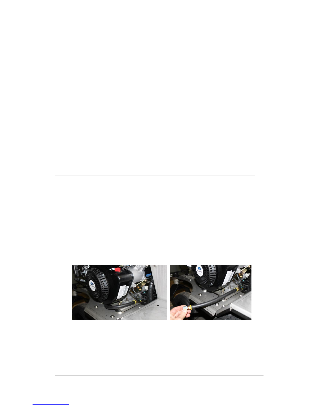
Safety guards are mounted on the backside of the Hydro-Gear Pumps (at the shin level of
the operator). These guards are designed to cover the hydraulic belt under the base and
protect the operator. Removing this guard could cause injury to an operator and could
void the Z-Spray’s warranty. Remove this guard ONLY when unit is turned off to do
preventative maintenance.
2.3 Operational Safety Rules
Never operate the Z-Spray without all covers, shields, and safety devices installed and
secured.
Never permit any person other than the operator to ride or board the Z-Spray at any time.
NEVER ALLOW RIDERS!!!
Use extreme care and maintain minimum ground speed when transporting on a hillside or
over rough ground, and when operating close to ditches, fences, or water.
The owner/user can prevent and is responsible for accidents or injuries occurring to
himself or herself, other people.
Operate only in daylight or good artificial light (min 200 lux).
Never allow anyone near the Z-Spray while in operation.
Only operate machine from the operator’s platform (Foot Pan), never operate machine
when standing on the ground.
Be alert for holes in the terrain as well as any other hidden hazards. Always drive slowly
over rough ground.
Never operate this machine on slopes exceeding 15 degrees in any direction. NOTE: To
operate on terrain that exceeds these limits constitutes misuse of the equipment and as such,
any and all injuries as a result of said use are expressly disclaimed.
2.4 Maintenance Safety Rules
Never perform maintenance on the Z-Spray when children are present.
Never allow anyone near the operation controls while performing service or maintenance
to the Z-Spray.
Keep the Z-Spray engine area free of accumulated debris, fuel, or excess grease and oil to
prevent fire hazard.
Page 3

Periodically tighten all nuts, bolts and screws and check that all fasteners are properly
installed to ensure that the Z-Spray is in safe operating condition.
Never perform maintenance on the Z-Spray while parking brake is disengaged.
2.5 Storage Safety Rules
Never store the Z-Spray in any area accessible by children.
Never store the Z-Spray with fuel in the tank inside a building where fumes could reach
an open flame or spark.
Allow the Z-Spray engine to cool before storing in an enclosed area.
Lubricate all moving parts of the Z-Spray to prevent rust during storage.
Remove all accumulated debris from the Z-Spray and attachments before storing.
SECTION 3 MAINTENANCE
3.1 Engine Maintenance (9.5 HP to 13 HP electric and pull start engine)
**USE COMPRESSED AIR (NOT WATER) WHEN CLEANING ENGINE**
Use only original equipment replacement parts. Other parts may not perform as
well, may damage unit, and may result in injury (Engine Manual)
Oil Recommendations: Manufacturer recommends the use of certified oils for best
performance. Use 4-Stroke automotive detergent oil of API service class SE or higher
grade
Outdoor temperatures determine the proper oil viscosity for the engine. Use the chart to
select the best viscosity for the outdoor temperature range expected.
If the oil level is below the ADD mark, add oil until it reaches the FULL mark. Start the
engine and check for proper pressure before continuing to operate.
(oil drain hose located on left side) (pull drain plug to side of frame)
Fuel Recommendations: Fuel must meet these requirements
Clean, fresh, unleaded gasoline.
A minimum of 87 octane/87 AKI (91 RON).
DO NOT FILL above the top of the fuel filter screen or the fuel may overflow
when it heats up later and expands
Full Maintenance Information Can Be Located In the Engine Manual Provided
Page 4

3.2 Hydraulic System Maintenance
Hydro-Gear recommends that the fluid and filter(s) be changed every 500 hours. Use any
type of motor oil in a 5W-40 Synthetic or equivalent.
Hydraulic system requires 25 micron hydraulic filters (part # 80404) or equivalent to be
used.
Check for hydraulic leaks daily to ensure proper fluid levels.
**Remove line(s) coming from the filters (at hydro pump end) to drain fluids**
After draining fluids, re-install hydraulic lines and tighten. Remove Hydraulic Filter and
replace with part # 80404 or equivalent. Tighten down and mark the hours the unit
currently has on the filter (with permanent marker). Remove Hydraulic Tank cap and fill
to mark (approximately 2/3rd to the top of tank) and re-install Tank Cap. Using a Floor
Jack or equivalent, lift the rear tires off the ground so that you can run the tires in the
forward and reverse positions without the unit moving (chock both the front and the back
of the front traction unit tires and if desired, block the frame for safety). Turn the unit on
and slowly run the rear wheels forward and then backward (repeating this process a few
times). This will purge any unwanted and unneeded air out of the system.
Turn off the unit, apply the parking brake and bring the unit back down to the surface.
Remove any chocks securing the front wheels and Floor Jack or equivalent out from
under the backside of the unit. Turn unit on, release parking brake and move the unit
forward and backward a few times. Hydraulic oil change completed.
3.3 Traction Unit Maintenance
The Z-Spray has 4 grease fittings that require periodic greasing. These locations can be
found on the wheel assembly (1 on each front wheel assembly) and on the caster
assembly (1 on each front caster assembly).
Page 5

Inspect wheel and caster assembly every 25 hours for bearing wear, damage, debris, and
proper installation.
Inspect all bolts, washers, nuts, pins and other mounting hardware of Z-Spray once a
week to ensure that hardware pieces are properly tightened.
3.4 Spray System Maintenance
The Z-Spray has both a granular spreader system as well as a liquid spray system.
Maintaining these two systems will ensure you years of use, proper calibration and limit
premature wear.
The spray system has a liquid storage tank of 20 gallons that can disperse a host of liquid
and/or wettable powder. To get maximum life and performance out of the spray system, it
is recommended that the tank, nozzles and hoses be flushed of all products after each use.
Storing product in system for an extended time may cause build up in hoses, premature
cracking on hoses, creating leaks in the hoses, clogged nozzles and filters, and a host of
other potential liquid system challenges (depending on your water source, not draining
the water out of the system and storing the Z-Spray dry can create algae build up).
Make sure that both In-line filter screen and nozzle tip screens are checked daily and
cleaned if needed. Clogged filters can lead to improper liquid dispersal and will create
inaccurate spray rates.
Keep hose reel valve in closed position when not in use. This will prevent the boom
nozzles from dripping due to pressure build-up in the coil hose.
Check 5 psi check ball screens daily. Build up on screen will create clogging and
inaccurate spray rates. Clogged screens can damage or hinder screens from working
properly.
Check spray system In-line filter rubber seal daily. Improper seal placement, missing seal
or filter not tightened down can create lose in pump pressure.
Check spray tips daily for any clogging of materials or foreign objects.
Clean out tank on daily basis for proper storing.
3.5 Spreader Maintenance
**USE COMPRESSED AIR (NOT WATER) WHEN CLEANING HOPPER**
The JR36R / ZS-ZS3620 Z-Spray come equipped with a 120 lb spreader. Recommended
maintenance suggestions are as follows:
Lubricate (Silicone Spray) Hopper, Deflector and Diffuser cables weekly.
Clean debris and product from Hopper daily to eliminate build up.
Keep hydraulic hose fittings tight and free of leaks.
Be sure that guides (4) are not damaged to allow the hopper door to slide freely
Page 6

Check agitator wire on a daily basis. If wire is not present, product will run the risk of
building up prior to reaching hopper door and not spreading evenly.
SECTION 4 Z-SPRAY OPERATIONS
4.1 Operations
Upon turning the key on to start the unit, apply full choke. Once unit has started, release
first the choke and then the brake. Push Joy Sticks forward (equally) to have the unit
move straight. Should you want to unit to backup in the reverse direction, pull back on
the Joy Sticks. If a turn is desired, push opposite Joy Stick of the direction you want the
unit to head forward (if wanting to turn left, push the right lever forward while keeping
the left lever slightly back of the right thus allowing the right tire to turn more than the
left. Push more on the left lever if you desire to turn the unit to the right). Be cautious as
turn radiuses change with the speed you are going and the amount each Joy Stick is
positioned forward or backward positions.
4.2 SPRAYING OPERATIONS
The spray system has the ability to spray in 4 different spray patterns. The wing
booms (left or right) each have their own nozzles creating a 48” liquid path on either side.
The middle boom is equipped with a single nozzle covering a 48” middle pattern
(NEVER SPRAY WILL ALL 3 DIRECTO VALVES IN THE ON POSITION).
Using both the left AND the right Directo Valves (pictured # 1), the unit is spraying 8’
wide. If JUST the middle Directo Valve is on (picture # 2), the unit is spraying 4’ wide
directly in the middle. If an operator needs to spray 4’ wide and offset the pattern, use
EITHER the left nozzle (picture # 3) or the right nozzle (picture # 4) depending on
what side of an offset you are attempting to accomplish.
(picture # 1) (picture # 2)
(picture # 3) (picture # 4)
Page 7

Creating pressure to these nozzles is done through the Throttle Valve. Threading the
Throttle Valve in (picture # 1) will create pressure to either the boom nozzles or the hose
reel. Threading the Throttle Valve out (picture # 2) will bring pressure to the tank(s) and
create agitation. If threading the Throttle Valve in does not create the desired pressure,
check your In-line filter housing and make sure that the O-Ring is present and the
housing is screwed on tight. If desired pressure is still not achieved, pressure adjustments
can be made at the pump (pictured far right). Clockwise turns create more pressure and
counter-clockwise turns decrease pressure.
(picture # 1) (picture # 2)
Throttle Valve in Throttle Valve out Pressure adjust on pump
to prepare spray to create agitation
If optimum pressure is achieved but boom nozzles are dripping, look at either your O-
Rings in your boom nozzles (may not be present or if present may not be seated properly)
or the hose reel valve may be open. Leaving the coil hose valve in the open position will
not allow the 5 psi check ball valves to close immediately when the pump is turned off.
This will create the nozzles to leak and drip for a short period of time upon shutting the
pump off, so make sure that your coil hose valve is turned to the off position if not in use.
Turning on the spray system can be done one of two ways. Your first option would be the
On/Off switch located on the control panel. This would be located on the lower/right side
of the control panel. The second way to turn the spray system on is the foot switch
located on the left side on the Foot Pan. This is the most common way to turn
on the spray system because it allows the operator to keep both hands on the control arms
and drive the unit. By applying pressure on the foot switch with your left foot, the spray
system is turned on. Releasing the foot switch will turn the spray system off.
There is a chrome valve that allows the 25’ Coil Hose to be opened. This is located on the
middle Directo Valve of you sprayer (pictured on opposite page). If not using the Coil
Hose for any applications, leaving the valve in the closed position will help the boom
spray nozzles close (stop spraying) quicker. This will alleviate any dripping from the tips
and potential turf damage (burning turf).
Page 8

(Hose reel Chrome Valve in closed position) (Hose reel Chrome Valve in open position)
Periodically check the in-line filter for any debris in the screen. If debris is present, this
can create erratic pressure spikes and/or not allow the proper flow through system. After
clearing any debris, ensure that rubber seal remains intact and tighten In-line filter cap (if
not installed properly, this will allow air to get in the system and system will lose or not
create pressure).
(In-line filter housing, screen & O-Ring) (In-line filter cap & O-Ring)
The On/Off pump switch located on the control panel turns on the spray system pump as
well as the spot spray Foot Switch on the left side of the foot pan. Once the pump is
turned on, the throttle valve is turned clockwise to increase pressure and/or counter-
clockwise to release pressure (and create agitation if the pump is on). The pressure can be
read on the gauge (decreasing pressure from gauge will increase agitation in the tank).
4.3 Spray Calibration/Tip Chart/Liquid Quantities
The Z-Spray liquid system comes standard with Red colored Turbo FloodJet tips which
will apply liquid material @ .32 (1/3) gallons per 1,000 sq. ft. @ 5 mph and 40 psi.
Different tips will be calibrated differently, so refer to the Calibration Chart for proper
spray volumes.
Your machine is capable of using tips from ¼ to 1 + gallons in size. See chart for your
desired drop rate.
The following are some general guidelines for sprayer calibration. Please refer to the
spray chart provided for complete calibration or use the given “Useful Formulas” section
to come up with your own calibration.
Page 9

Useful Formulas
GPM = GPA x MPH x W
(Per Nozzle) 5,940
GPM = GAL/1,000sq ft x MPH x W
(Per Nozzle) 136
GPA = 5,940 x GPM (Per Nozzle)
MPH x W
GAL/1,000sq ft = 136 x GPM (Per Nozzle)
MPH x W
GPM - Gallons Per Minute
GPA - Gallons Per Acre
GAL/1,000sq ft - Gallons Per 1,000 Square Feet
MPH - Miles Per Hour
W - Nozzle Spacing (in inches) for broadcast spraying
- Spray width (in inches) for single nozzle, band spraying
- Row spacing (in inches) divided by the number of nozzles per row
The throttle valve adjusts pressure. The throttle valve is located just before the return
valves near the left side control panel. Turn clockwise to increase pressure, counter
clockwise to decrease pressure (pictured on page 8). Pressure will be displayed on the
gauge near the control panel. Once the nozzles are opened, you will notice a slight
decrease in pressure (adjust accordingly), so quick adjustments will need to be made.
To determine liquid quantities per tank, understand what tips you have on your machine
(factory set is 1/3 gallon per 1,000 sq. ft. through the Red tips). For instance some
products call for 1.1 to 1.5 oz per 1,000 sq. ft. We would recommend using 1.3 (median
value of 1.1 to 1.5). Since you are using a 1/3-gallon tip, you need to multiply by 3, and
then multiply that number of gallons you need to put in your tank.
1.3 (median value of 1.1 to 1.5) X 3 (1/3 gallon tips) X gallons needed. If you were filling
a 20-gallon tank your equation would look like this:
1.3 X 3 X 20 = 78 ounces to 20 gallons of water.
Page10

*Turbo FloodJet Tips used ONLY on boom less units*
ALERT!!! Never operate all 3 nozzles at the same time (refer to manual
for examples)
PSI
Drop
Size
CAPACITY
ONE
NOZZLE
IN GPM
CAPACITY
ONE
NOZZLE
IN
OZ./MIN
_______SPACING__________
/\ 34”/\
GALLONS PER 1,000 SQ. FT.
3 MPH
4 MPH
5 MPH
STF-VS2
10
XC
0.20
26
0.27
0.20
0.16
20
XC
0.28
36
0.37
0.28
0.22
30
XC
0.35
45
0.47
0.35
0.28
40
XC
0.40
51
0.53
0.40
0.32
XC
STF-VS2.5
10
XC
0.25
32
0.33
0.25
0.20
20
XC
0.35
45
0.47
0.35
0.28
30
XC
0.43
55
0.57
0.43
0.34
40
XC
0.50
64
0.67
0.50
0.40
XC
STF-VS3
10
XC
0.30
38
0.40
0.30
0.24
20
XC
0.42
54
0.56
0.42
0.34
30
XC
0.52
67
0.69
0.52
0.42
40
XC
0.60
77
0.80
0.60
0.48
XC
STF-VS4
10
XC
0.40
51
0.53
0.40
0.32
20
XC
0.57
73
0.76
0.57
0.46
30
XC
0.69
88
0.92
0.69
0.55
40
XC
0.80
102
1.07
0.80
0.64
XC
STF-VS5
10
XC
0.50
64
0.67
0.50
0.40
20
XC
0.71
91
0.95
0.71
0.57
30
XC
0.87
111
1.16
0.87
0.70
40
XC
1.00
128
1.33
1.00
0.80
XC
STF-VS7.5
10
XC
0.75
96
1.00
0.75
0.60
20
XC
1.06
136
1.41
1.06
0.85
30
XC
1.30
166
1.73
1.30
1.04
40
XC
1.50
192
2.00
1.50
1.20
XC
STF-VS10
10
XC
1.00
128
1.33
1.00
0.80
20
XC
1.41
180
1.88
1.41
1.13
30
XC
1.73
221
2.31
1.73
1.38
40
XC
2.00
256
2.67
2.00
1.60
*Boomless units include Junior 36 units built prior to 2009 and JR36R units*
Page 11

4.4 Spreader Operation
The JR36R / ZS-3630 Z-Spray unit is equipped with a 120 lb spreader. The
hydraulic hopper motor with the spreader control rate knob allows variable spread widths
from 3 to 25 feet. This depends on volume/density, particle size and rate of travel, and
weather conditions. The pattern can be increased or decreased while spreading depending
on needs. The spread thins or feathers at the outer edges, eliminating sharp “edge of
spread” lines, which cause stripes and streaks. Determine a dial setting on the low side. If
setting is too low, cover the area more than one time. A higher setting can be used when a
proven dial setting is established. Travel at a constant speed for consistent results.
Remember-Published dial settings are approximate only. Open the hopper door after
the spreader is turned on at operating speed.
Using the spreader system, there are 3 cables to operate the hopper door (far left cable),
the diffuser (middle cable) and the deflector shield (lower right cable). By pulling on the
far left hopper door cable, this will open the door and allow product to fall on the spinner.
Adjustments as to how wide the door opens are made on the front on the hopper with the
white knob (Rate Dial). This limits how wide the door will open and how much granular
product will be coming out. The diffuser cable (middle cable) controls the spread pattern.
Turning the cable knob counter-clockwise will loosen the cable lock and allow you to
adjust (pull further out or push further in) this cable. Doing this will allow you to spread
granular product heavier to the left, consistent in the middle or heavier to the right. Once
you have adjusted to your desired pattern, turn the knob clockwise to lock in position.
The lower cable on the far right hand side is the deflector shield cable. This cable allows
you to lift and lower the deflector shield accordingly. During normal spreading
applications, the deflector shield would stay in the up position and cable would be
extended out all the way. When wanting to close off the left side and use the deflector
shield, push in the cable and the shield will drop down blocking off granular product on
the left side. This cable is identical to the middle diffuser cable so needs to be turned
counter-clockwise to loosen and then clockwise to lock in position
5.1Spreader Calibration/Layout
The Spreader Motor Control determines the speed of the impeller in the front on the
machine. The flow is controlled by increasing or de-creasing fluid flow to the hopper
motor. Your machine is capable of varying its spread pattern from 3 –25 feet with this
control. Being hydraulically driven, the spread pattern is independent of the ground
speed.
The hopper control cable opens and closes the door inside the base of the hopper. The
maximum size of the opening will be determined by the rate adjustment on the knob dial.
This will set your rate gate linkage bar to limit and stop the rate the door can open.
The Diffuser adjustment allows the user to adjust the intensity of the spread pattern
(heavier left or heavier right). A small pull of the cable shifts the product placement on
the impeller. This in turn balances the spread pattern heavier to the left (back side ramp)
or heavier to the right (front side ramp). *FOR MORE DETAILED INFORMATION,
GO TO WWW.SPYKER.COM Page 12

(Diffuser, Deflector & Hopper cable) (Hydraulic hopper motor)
(Rate Dial) (Diffuser shown on underside of opening)
SECTION 5 PARTS
5.1 Part Number / Pictorial
Page 13

Electric Parts
Part # Description Qty
80202 Pump on-off switch 1
80204-2010 Spot Spray Switch (foot switch only) 1
80205 Wiring Harness 1
80206 30 AMP Fuse 1
80207 Starter Solenoid 1
80208 Battery Box 1
80120-2010 12 Volt Battery (*cannot ship, local pickup only*) 1
80214-A Tach/Hour Meter 1
80215 Key Switch 1
(wiring harness) (foot switch, tach/hour meter, etc) (battery box)
Wheel Parts (front and rear)
Part # Description Qty
80019-MM Front 13” Wheel Assembly 1
80019-B Front Wheel Spacers 2
80309 Front Wheel Cone Bearings 2
80311 Front Wheel Bearing Cup (for replacement only) 2
80020 DM-808 Rear Wheel Assembly 1
80310 Rim Seal 2
HHCSC5-3410 Front Wheel Bolt 1
NNC-34 Front Wheel Nut 1
FW-SAE-34 Front Wheel Washer 1
80021 Rear Wheel Assembly (not pictured) 1
80020 Rear Junior or Junior 36 Wheel Assembly (not pictured) 1
Page 14

Caster Parts
Part # Description Qty
NS-10061-L Left Side Locking Caster 1
NS-10061-R Right Side Locking Caster 1
80306 Dust Cap 1
80308 Caster Bearing 2
80009 Castle Nut 1
80302 Caster Bearing Seal 2
CP18X112 Cotter Pin 1
Spot Spray Gun
Part # Description Qty
60040 Spot Spray Gun 1
60041 Spot Spray Tip 1
60029 ¼” MPT X 3/8” Barb 1
Page 15

Manifold Assembly
Part # Description Qty
60049 ½ MPT X ¾ HOSE BARD 90 DEGREE 1
60023 ½ TO ¼ BUSHING 1
60022 ½ FPT TEE 1
60058 ¾ MPT X ½ MPT REDUCING NIPPLE 1
60032 GAUGE, 60PSI 1
60010 DIRECTO VALVE \ AA6B 3
60027 ½ MPT X ½ HB 90 3
60026 ¾ MPT X ½ HB 90 1
60012 THROTTLE VALVE 1
60042 ¼ TO 3/8 BARB 90 1
60009 ¼ CHROME VALVE 1
60020 ¾ MPT CLOSE NIPPLE 2
(Picture from the front of the unit. When standing on the unit, part #60012 will be on the left side)
Locking Caster System
Part # Description Qty
NS-10136-L Locking Caster Locks left (2015 to current) 1
NS-10136-R Locking Caster Locks right (2015 to current) 1
NS-10153A Locking Caster front T Bar (2015 to current) 1
NS-10061-R Locking Caster Right (2015 to current) 1
NS-10061-L Locking Caster Left (2015 to current) 1
NS-10157 Locking Caster Pedal (2015 to current) 1
NS-10156 Locking Caster Pedal Bracket (2015 to current) 1
80022-24.5 Locking Caster Linkage (2015 to current) 1
Page 16

Parts List
80020
JUNIOR REAR WHEEL ASSY 20X8X8
2
ea
80019-MM
FRONT ZPLUG WHEEL ASSY. 13X6.5X6
2
ea
80200-Striker
Trail Tech Striker Speedometer
1
ea
80202
PUMP ON-OFF SWITCH\nCH-M-58031-01
1
ea
80204-FOOT
SWITCH ASSY.
FOOT SPOT SPRAY SWITCH ASSY. 2010FS-01
1
ea
80210
12 VOLT BATTERY\nSS11UL1 CCA350
1
ea
80215
KEY SWITCH\n4F463
1
ea
80214-A
TACH/HOUR METER
1
ea
80301
CUP BEARING CASTER YOKE\nL44610 (RACE)
4
ea
80305
RELIABLE # SA-1350 (CASTER SPINDLE)
2
ea
80305-6.5
Spindle 6-1/2 long
2
ea
80306-R
DUST CAP, RUBBER
2
ea
80308
L44649 BEARING CONE
4
ea
80352-36R
JR 36R WHEEL HUB-4 HOLE (r only)
2
ea
80403-P
2 QT Flambeau Hydro Tank
1
ea
80404
HYDRAULIC FILTER\nAA0513 (SINGLE filter from May 2011 to present)
1
ea
80420
1/2' PUMP FITTING (4)\n6802-08-08-4
4
ea
80430-PV
HOPPER MOTOR FLOW CONTROL VALVE
1
ea
70008
SMALL HOPPER COVER 120
1
ea
70013
DIFFUSER/DEFLECTOR SHIELD CABLE (LOCKING)
2
ea
70014-A
120LB HOPPER CABLE
1
ea
70052-120
120 LB HOPPER KIT n/KSp01-LTR1
1
ea
60010
DIRECTO VALVE AA6B
3
ea
60012
THROTTLE VALVE\n23520-3/4-PP
1
ea
60032
GAUGE\nRICH 60-25
1
ea
60014-A
4.0 GPM PUMP\n5940-111C W/BUTT CONNECTORS
1
ea
80205-36R
JR36R IGNITION HARNESS
1
ea
87001
KOHLER REMOTE CHOKE 17 755 16-S
1
ea
87000
KOHLER 9HP CH395 ENGINE (2015 and current)
1
ea
80500-Robin
9HP Subaru Engine (2011 to 2014)
1
ea
70024-B
SHAFT COUPLER, MTE
1
ea
80313
MTE HOPPER MOTOR CAP
1
ea
80316
3/8 Flange Bearing (Hopper shaft)
1
ea
80620
JR36R WHEEL MOTOR RIGHT
1
ea
80621
JR36R WHEEL MOTOR LEFT
1
ea
80510
Throttle Cable
1
ea
86141
JUNIOR 36R T-HOSE ASSY
1
ea
70029
CABLE WIRE SCREW AND RETAINER
1
ea
S5DFA12
PUMP FITTING\n5DFA12 straight
1
ea
S5DFE12
PUMP FITTING\n5DFE12 90 degree
1
ea
10058
bulkhead, 1/2" (hole requirement 1 1/4") (2015 and current)
2
ea
60122
36R 20 Gallon Tank (2015 and current)
1
ea
60078
1/2 CPVC MIP Adapter
2
ea
87002
Kohler Exhaust Deflector
1
ea
STF-VS2
TURBO FLOOD RED
3
ea
80064
SS- FRONT CASTER TUBE
2
ea
80303
JOY STICK BUSHING\nKAMAN# EF 0812-12
4
ea
60050
3/8'' SINGLE BRAID HOSE\n000612
17
ft
80023
LOWER LINKAGE ROD END\n367-QI312
2
ea
30700
DASH PANEL DECAL
1
ea
30707
Hopper Cable Decal
1
ea
30400
VIBRATION ISOLATOR 2NPC5 JR36R
4
ea
30705-JR36R
SPRAY CHART JR36R
1
ea
Page 17
This manual suits for next models
1
Table of contents