Lab:One Recordings ReQ 131 User manual

ReQ·131 Instruction Manual
v
1.2
ReQualizer
31 ISO Band Graphic E
q
ualizer
Rack Extension for Reason
Instruction Manual

Page 2
ReQ·131 Instruction Manual
v
1.2
Contents
Page Subject
3: Thank You, Acknowledgements & Dedications
4: Introduction
5 - 8: A brief guide to the ReQ·131
9 - 13: Working with the ReQ·131
14 - 15: Selecting the Signal Path and dB ranges
16: HEAR EQ mode and how it works
17: CV inputs and controls
18: How to save and load presets
19 - 20: How to ‘latch’ your own MIDI via Remote Overriding
21 - 22: Appendix 1: Instrument frequency ranges
23 - 24: Appendix 2: EQ Tables
25 - 26: Licence Agreement

Page 3
ReQ·131 Instruction Manual
v
1.2
THANK YOU
Thank you very much for expressing your confidence in our products by purchasing one of our
equalizers, the ReQ·131. This 2-channel high-quality equalizer was designed with our experience of
both filtering capabilities in the digital realm as well as the crafting of audio for all types of users;
producers, engineers and artists alike.
We hope you continue to enjoy using the ReQ·131 in your projects for now and for future.
Lab:One Recordings © 2013
ACKNOWLEDGEMENTS
Thanks to the ReQ Squadron for all the testing, comments, suggestions and feedback.
Original coding support from Andrew Best (c/o Blamsoft).
Additional support from Unfiltered Audio (Michael & Josh).
Propellerhead Software (for Reason, the SDK and the concept of the Re)
Presets designed by:
Key User Preset type
[LB1] djfresha c/o LAB:ONE Recordings ReQ·131 presets
[SE] ScuzzyEye Combinator presets, within ReQ·131 RE
[GVB] vernon22 ReQ·131 presets
DEDICATIONS
This Re is dedicated to all the Propellerhead Reason users & forum threaders, friends, & colleagues we
have spoken to over the years.
DjFresha: Thanks goes out to my studio buddies; Dos aka Orco, Puggy, Mist, and Dj EQ, for the
support & feedback, shouts go out to all who know me, including FLAVAUNIT crew (Jayeye & Becky,
Dj D & Caroline C, Andy ‘Ruthless’, Ben ‘Devious’ & Scott ‘Sniper’), REBIRTH massive & head honcho
Aybee, SUBTRONIK crew (G.I Jones & Damo), good long time friends Kealey ‘Keels’, Chris ‘Drope’,
John ‘Little-John’, Stacey ‘The Duchess’ & Nick ‘Gibbo’ Purnell.
Also not forgetting my family for the support, and last but by no means least, my wife Alicia who after
waiting for me to code this up is now a happy bunny :D
Now let’s get into the ReQ·131….

Page 4
ReQ·131 Instruction Manual
v
1.2
Introduction
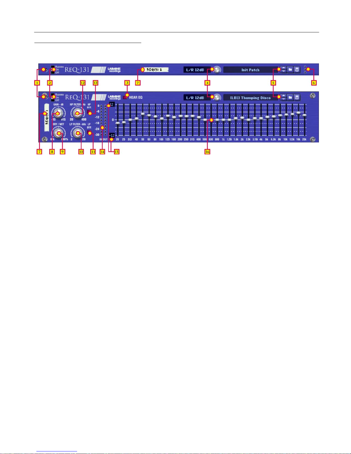
The ReQ·131 31 ISO band graphic equalizer is a dedicated rack unit, built as a Rack Extension for the
Propellerhead Reason environment. This device has a maximum of what would be 2U space in the real
world. Being a Rack Extension (Re), this gives you various options of versatility within your projects.
The ReQ·131 features 31 stereo-linked frequency bands, plus a high-pass and low-pass filter, and
includes a gain control (see ‘A brief guide of the ReQ·131’ section). All these controls are adjustable to
suit your application, and these settings can be stored as your own presets, so you can recall them
again and again at a later time (see ‘How to save and recall presets’ section).
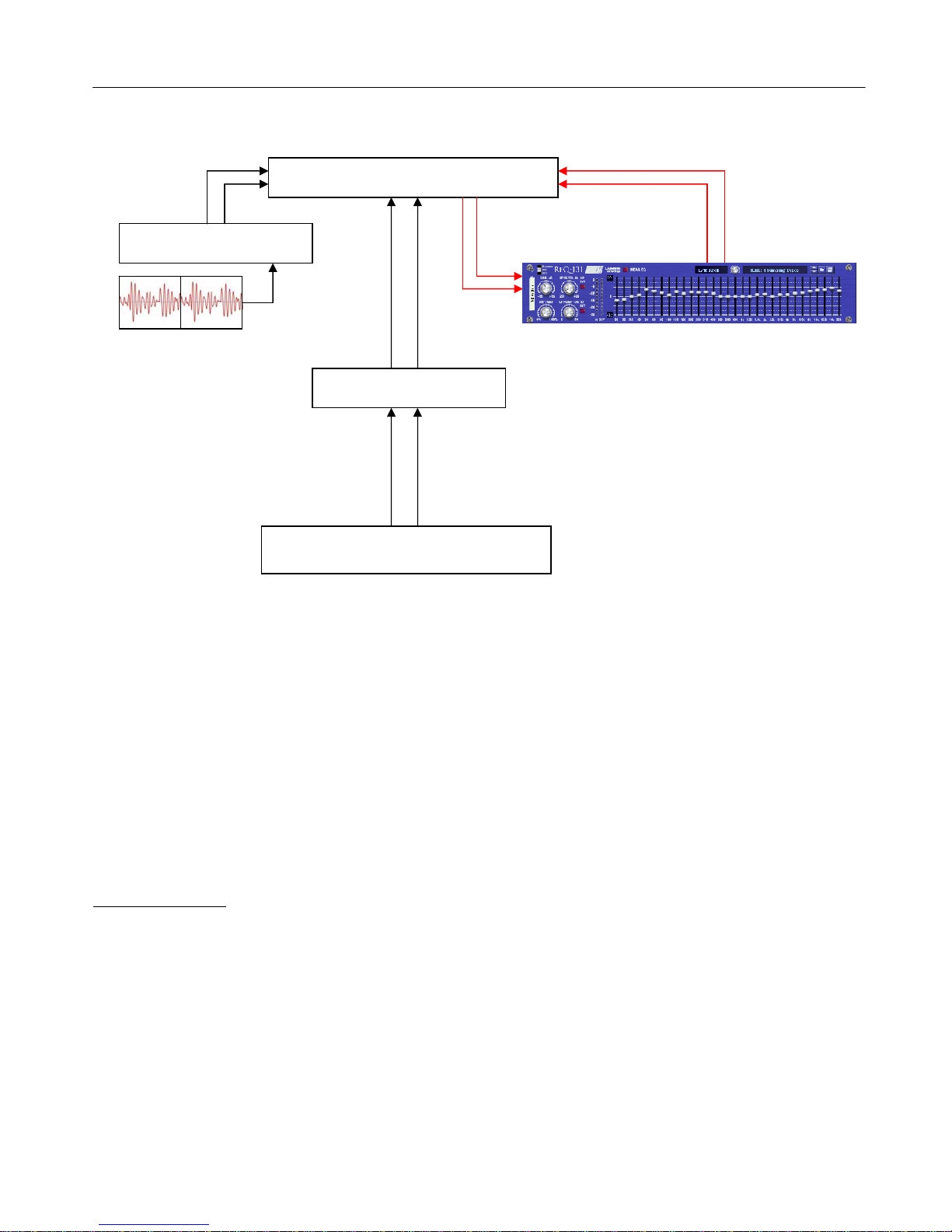
The ReQ·131 features two audio inputs and two audio outputs, which are processed independently,
which allows you to have two totally separate signals being processed together at the same time using
one set of controls. Mono operation is also an option (see ‘How to connect audio’ section).
ReQ·131 has some other controls which have been developed over time with the audio engineer and
the musician in mind. Since v1.2 the inclusion of the following can be found:
31 CV (control voltage) sockets, with independent trim knobs, independent bi-polar and uni-
polar buttons, and invert CV signal buttons, plus a CV trim scale knob which adjusts all CV
inputs by scaling (alike how an audio buss fader would work). See the ‘CV inputs and controls’
for more information.
STEREO equalisation, MID equalisation, SIDE equalisation (both left and right signals are
linked). See the ‘Selecting the Signal Path and dB ranges’ section for more details
5 dB range modes (3dB, 6dB, 12dB, 18dB, 24dB), for subtle shaping to signal carving.
LPF BYPASS and HPF BYPASS buttons – to allow you to bypass the effect of the LOW PASS
and HIGH PASS filters.
HEAR EQ mode which aid you further with your audio massaging and sculpting.
See the ‘HEAR EQ mode and how it works’ section.
a DRY/WET knob, which now gives even more control between original signal and processed
signal, to obtain a medium between full effect and bypassed audio.
For reference, the 31 ISO bands are:
20Hz, 25Hz, 31.5Hz, 40Hz, 50Hz, 63Hz, 80Hz, 100Hz, 125Hz 160Hz, 200Hz, 250Hz, 315Hz, 400Hz,
500Hz, 630Hz, 800Hz, 1kHz, 1.25kHz, 1.6kHz, 2kHz, 2.5kHz, 3.15kHz, 4kHz, 5kHz, 6.3kHz, 8kHz,
10kHz, 12.5kHz, 16kHz, & 20kHz.
On a thirty-one band graphic equaliser, each band covers one third of an octave.
The ReQ·131 is designed to be a transparent effect, meaning that if no adjustments are made on the
device, the audio passing through the effect is ‘clean’ and has not been affected by the equalisation
filters or the low pass or high pass filters. This is the ideal, so that no coloration is applied to the sound.

Page 5
ReQ·131 Instruction Manual
v
1.2
A brief guide of the ReQ·131
The ReQ·131 is based on most hardware 31-ISO band equalizer units.
The Front Panel (folded & unfolded views)
FOLD-UNFOLD [1] – To allow the RE to be maximized or minimized
BYPASS SWITCH [2] – To determine signal flow (BYPASS effect, effect ON, or effect OFF)
HEAR EQ button [3], to isolate and examine your EQ effect (see ‘HEAR EQ mode and how it works’)
SIGNAL PATH AND DB MODE dropdown/selector knob [4], to select audio signal mode & db range
PATCH NAME and PATCH BROSWER [5] buttons; for loading & saving presets.
MINI OUTPUT LEDs [6] to indicate signal output signals when ReQ131 is folded.
TAPE STRIP [7] – Used to identify the RE. Double click to edit.
GAIN [8] – A trim control to boost / cut overall volume by +/-15dB.
DRY/WET [9] – A mix control between affected audio and original signal.
LOW PASS FILTER [10], HI PASS FILTER [12] knobs; to remove frequencies at 12dB / octave roll off.
Frequency setting determines the point where the roll off begins.
LOW PASS BYPASS [11], HI PASS BYPASS [13] buttons; to bypass the filters.
INPUT LEDs and OUTPUT LEDs [14] to indicate signal input & output, for re-balancing aid.
dB RANGE UNIT displays [15] indicating the min / max dB level of the scale (set by the SIGNAL PATH
AND DB MODE selector)
FREQUENCY BAND faders [16] – boost or cut at the set frequency (fixed Q of 1/3rd octave)
The GAIN knob can attenuate between -15dB through to +15dB. This allows you to decrease the gain if
you raise the fader bands, or increase the gain if you lower the bands (see ‘Working the ReQ·131 in
practice’).
The DRY/WET knob can be used to mix between wet and dry affected signals. This can be used creatively,
to scale the amount of unprocessed signal with the processed signal (pre-filter mix control).
The LOW PASS and HIGH PASS knobs are high pass and low pass filters. These attenuate certain
frequencies depending on the setting at a rate of -12dB per octave. These are used to ‘cut away’ the high
frequency content (Low passing) of the audio and the low frequencies (High passing). If you set the Low
Pass dial to 10 kHz, this would mean that at 20 kHz the audio signal at that point in the frequency range
would be reduced by 12dB (think simply using the dials as precise ‘bass’ and ‘treble’ reducers).
NOTE: 1 octave range is exactly half or exactly double the current frequency setting, so if 500Hz is the
chosen frequency, 1 octave down is 250Hz, and 1 octave up is 1000Hz. This applies to all frequencies.

Page 6
ReQ·131 Instruction Manual
v
1.2
The FREQUENCY BANDS are set so they can manipulate the specific frequencies they are set to. They can
be used to attenuate the set frequency between minimum and maximum dB range, set by the SIGNAL
PATH AND DB MODE dropdown. The bandwidth (known as ‘Q’ in equalizer terms) is specifically set at
1/3rd Octave. This allows you to create ‘curves’ with the faders, without ‘overlapping’ of frequency bands
(prevents possible phase shifting or other undesired audible side effects). If you push two bands side by
side on the ReQ·131, then the combination of both bands would make a wider ‘band’. This is how
equalizers of this design should work. All faders as of v1.2 now indicate a percentage figure, so if you are in
12dB mode and have the fader set to +75%, the fader would attenuate +9dB at the chosen, if set to -50%,
the fader would attenuate the signal -6dB at the chosen frequency.
The SIGNAL PATH AND DB RANGE dropdown display allows the user to select between 15 options;
these are a combination of 3 signal paths and 5dB modes. See the ‘Selecting the Signal Path and dB
ranges’ for more information.
The HEAR EQ button is a new approach to equalisation for ReQ·131, in that you can hear the effect of
your equalisation settings by turning this feature on. See the ‘HEAR EQ mode and how it works’ section
for a more in-depth explanation.
The dB RANGE displays are dynamic labels which update in accordance to the SIGNAL PATH AND
dB RANGE dropdown. They will display the maximum and minimum dB settings for that active mode.
The BYPASS SWITCH is used to enable / disable / bypass the ReQ·131.
The PATCH SELECTOR is used to save, load and browse presets for the ReQ·131
The TAPE STRIP is used to show the name of the device. Double click to rename the device.
The FOLD / UNFOLD arrow is used to minimize or maximize the Rack Extension.
The INPUT and OUTPUT LEDs are used to assess initial input levels pre-EQ, and final output levels
post-EQ and post-Filters. See ‘Working with the ReQ·131’ for more details on usage.

Page 7
ReQ·131 Instruction Manual
v
1.2
The Back Panel (folded & unfolded views)
FOLD-UNFOLD [1] – To allow the RE to be maximized or minimized
TAPE STRIP [7] – Used to identify the RE. Double click to edit
CV INPUTS, CV Inverts & CV Bi-polar / Uni-polar modes [17] are used to affect each of the 31 faders
independently, and would affect the attenuation of the band filter.
CV TRIM SCALE [18] affects all CV inputs by a set scale (between 0% and 100%), for fine tuning of
CV input signals. For more information see the ‘CV controls and input options’ section.
AUDIO INPUTS and AUDIO OUTPUTS [19] sockets; to connect the RE to various other devices via audio
cabling.
The FOLD / UNFOLD arrow is used to minimize or maximize the Rack Extension.
The TAPE STRIP is used to show the name of the device. Double click to rename the device.
The AUDIO SOCKETS are used to connect your ReQ·131 to various modules within the Propellerhead
Reason environment, in a form of either an insert or a send effect (see ‘Working the ReQ·131 in practice’).
Connecting up the audio sockets can be done automatically by Reason, or can be manually done to your
own requirements. Mono devices, when connecting a new ReQ·131 to them, can automatically route their
mono signal in to the left channel, and the left output of the ReQ·131 is connected to the originally wired
socket of the mono device, closing the audio loop. Stereo devices can automatically connect their outputs
to the left and right inputs of the ReQ·131, and the ReQ·131 completes the audio chain by connecting its
outputs to the originally connected stereo pair sockets.
ReQ·131 processes audio in 3 methods, determined by the SIGNAL PATH; the choices available are Left &
Right processing (both channels are independent of each other, and are equalised together) MID-only
processing (which analyses the left and right input, determines what is the same information in both
channels, and equalises the MID signal) or SIDE-only processing (which analyses the left and right input,
determines the difference between the left and right signal information and equalises the SIDE signal).
These three signal paths are discussed further within the manual (see page 14)
The CV SOCKETS and CONTROLS are used to extend the possible usage of the ReQ·131 in a ‘dynamic’
sense, so the faders can be controlled by another device by use of CV (control voltage) information. This
can be LFOs or envelopes, or even audio converted to CV (using Scream 4’s ‘follower’ CV socket, THOR’s
Mod Matrix to receive audio in and process out via the CV out sockets, or Pulverisor’s follower CV socket, or
even the M-Class Compressor Gain Reduction CV output socket).
NOTE: If using MONO signals whilst ReQ·131 is in MID or SIDE mode, the result would be the same as
L/R mode, due to MONO signals have no stereo content naturally.

Page 8
ReQ·131 Instruction Manual
v
1.2
How to connect audio
To connect the ReQ·131 you can use Reason’s own auto-connection system, and the ReQ·131 will
decide the best way to auto-wire; if you have a mono-output device (Subtractor, for example), and you
wish to add a ReQ·131 to it, the ReQ·131 will auto-connect the Subtractor output to the Left input, and
then continue to route the Left output of the ReQ·131 to the Left input of the mix-channel (or next
device in your processing chain).
You can do any of the following to create the ReQ·131;
a) right-click (Win) / CTRL-click (Mac) on the device, select ‘Create Device’, choose sub-menu ‘Studio
Effects’, and select ‘ReQ·131 (31 Band EQ)’ from the listing.
b) with the device selected, use the ‘Create’, select ‘Create Device’, choose sub-menu ‘Studio Effects’
and select ‘ReQ·131 (31 Band EQ)’ from the listing
c) using the Tool Palette in Reason (F8), select ‘Studio Effects’ when in the ‘Devices’ tab, and locate
the ‘ReQ·131 (31 Band EQ)’ device, click on the icon and drag it to the device you wish to add it to.
How to connect CV cables and sockets
To connect the ReQ·131 CV sockets, you require a source CV signal, which could be from a synth
module or effect module within Reason. Only information from a CV output on the source device can
connect to the CV inputs on the ReQ·131.
To connect the source CV out to any of the CV inputs of the ReQ·131 simply click-hold with your
mouse on the CV out socket of your source device and drag the yellow cable to the CV input of your
choice.
See page 15 for more information on how to use CV controls.
NOTE: CV cable configurations can only be saved and re-loaded within a Combinator device or a Mix
Channel / Audio Channel Combinator unit. Also, any Combinator patches using ReQ·131 with external
routings (ie a CV input from a device outside of the Combinator) will not recall the correct configuration.
Song files however will remember CV connections and CV knob settings.

Page 9
ReQ·131 Instruction Manual
v
1.2
Working with the ReQ·131
The ReQ·131 is designed to be a flexible device, allowing it to be used however you see best fit. Only
typical applications will be listed in this manual.
Experiment with setups to your own way of working, use these as a guide, but not necessarily as the be-
all-and-end-all approach.
A) Using the ReQ·131 as an insert (mix channel setup).
In setup (A), this would use the ReQ·131 as an insert effect. This means that whatever control you
adjust on the ReQ·131, it will affect the total sound coming out of the sampler / synth module. If the
ReQ·131 is in bypass mode or has the ‘Factory settings’ preset loaded, the audio playing would still
sound ‘clean’ and unaffected.
To affect the sound, begin with adjusting the Gain dial if you have a low signal (or alternatively, raise the
signal on the sampler / synth module). Low Pass and High Pass dials to taste (not compulsory). Low
passing will ‘dull’ the sound by suppressing the higher frequencies, while High passing would remove
some ‘body’ from the lower end of the frequency spectrum. Adjust the faders on the graphic equalizer
to compliment the sounds you wish to ‘bring out’. To help you, refer to Appendix 1: Frequency Band
‘character’ descriptions. To finalise the adjustments, use the gain dial to return the audio back to the
same level pre-equalization. What this allows you to do is to be more subjective with your eqing
decisions, to see if improvements have occurred. If you leave the level higher after equalization, the
natural ‘boost’ in level gives a false pretence to the ear, making you believe it is better sounding (purely
because of being at a slightly higher level). Remember to equalize carefully, so not to make wrong
decisions too quickly.
Reason sampler / synth module
Reason
Mix Channel
ReQ Ri
g
ht In
p
ut
ReQ Left In
p
ut
Ri
g
ht Out
p
ut
Left Out
p
ut
ReQ Ri
g
ht Out
p
ut
ReQ Left Out
p
ut
Mix Channel
Right Input
Mix Channel
Left Input
Reason
Master Channel

Page 10
ReQ·131 Instruction Manual
v
1.2
B) Using the ReQ·131 as a send effect (mix / audio channel setup).
In setup (B), this would use the ReQ·131 as a send effect. This means that whatever control you adjust
on the ReQ·131, it will affect the sound coming from the Master Section at a set amount, determined by
the Send Effect dial on that specific Mix / Audio channel. This means you can have a clean sound mixed
with an altered equalized sound. This is known as Parallel Processing, and may be desired in some
cases.
Again you can adjust the ReQ·131 as mentioned in setup (A) above, with the addition of the SEND dial
located on the Main Mixer in Reason. Full left setting of the SEND dial has no effect on the sound, while
full right setting of the SEND dial will send a maximum level possible to the ReQ·131. This means you
can have one ReQ·131 as a send device for all your audio channels. However, latency may have a side
effect of cancellation of audio (aka phasing), due to the processing time needed to perform the filtering
of the ReQ·131, when used as a Send effect.
Alternative setups
For devices which have multiple outputs (ie NN-XT, Redrum, Thor, Spider Audio), then if required
additional ReQ·131’s could be added as either mono-devices (only connecting left audio input & output
sockets), or as stereo devices. This in turn allows you to edit specific sounds within a preset if you so
wish (ie split zone instrument patches may have a bass guitar for one half of the keymap, while a synth
lead is using the other half, and you wish to effect the sounds independently). See the next page for
more examples of setups.
Another possible option would be to use one instance of ReQ·131, and have 2 mono devices linked
into it, and process both inputs in parallel, and output the two signals to two separate mixer channels.
This may be desired to help use the same eqing settings on two mono devices at the same time.
Reason sampler / synth module
Reason
Audio Channel 1
Mix channel 1
Right Input
Mix channel 1
Left Input
Right Output
Left Output
ReQ·131
Inputs
Reason
Master Section
Reason
Mix Channel 1
ReQ·131
Outputs
Return inputs
Send
Outputs
Audio Clips
on sequencer

Page 11
ReQ·131 Instruction Manual
v
1.2
C) Using the ReQ·131 as an insert to a side-chain (mix / audio channel setup)
Above you will see two alternative setups using the ReQ·131 as part of a side-chain effect signal path.
The method on the left utilises the Audio Channel insert sockets, to send signal from the Audio clips on
the sequencer through the SSL desk channel strip. The insert sockets send the original signal to the
ReQ·131, which then can alter the signal by using the 31 band faders, the gain knob and the Low Pass
& High Pass filters, to ‘exaggerate’ the signal more. Reason for doing this may be to use the ReQ·131
to help with sibilance and plosive sounds which can be found in vocal recordings. From the ReQ·131
the outputs are then fed into the channel strips own side-chain sockets, and the ‘KEY’ button will
become active on the SSL desk, indicating that the side-chain functionality of the compressor found on
the SSL desk is in operation.
Method 2 on the right shows a similar setup, but using a Spider Audio Splitter unit to divide the original
signal / sound source into two parallel pairs of signals, one set is sent to the M-Class Compressor unit
audio inputs, while the second pair from the Spider is sent to the audio inputs of the ReQ·131, and the
outputs of the ReQ·131 are connected to the side-chain input of the M-Class Compressor. This frees
the side-chain of the SSL compressor, so another sound source could be used to control the main SSL
dynamics for that channel strip.
Reason
multi-channel
sampler /
synth module
Reason
Audio Channel
Reason
Master Section
Audio Channel
Insert outputs
ReQ·131 inputs
Audio Channel
Sidechain inputs
Audio Channel
Outputs
Spider Audio Splitter
M-Class Com
p
ressor
Reason
Mix Channel
ReQ·131 inputs
Setup A:
Side-chaining the SSL Compressor
M-Class outputs
Original signal (via Spider)
M-Class Comp.
Sidechain inputs
ReQ·131 outputs
Module outputs to Spider Split inputs
Setup B:
Side-chaining using M-Class Compressor
Audio Clips
on sequencer

Page 12
ReQ·131 Instruction Manual
v
1.2
D) Using the ReQ·131 to process MID and SIDE signals in series
In setup (D), this approach uses 2 ReQ·131’s in series (one after the other), as an insert chain. The
difference between this setup and prior setups is that the mode is set for each ReQ·131 to process the
specific Mid / Side signals, rather than effect the full signal coming out of the sampler / synth module.
ReQ·131 #1 has been set to ‘MID 12dB’ mode, meaning that whatever we change on the front panel*
of this particular instance will affect ONLY the MID content of the audio signal. What in turn this will do
is attenuate frequencies found ‘centrally’ to the mix (also known as ‘phantom centre’), so central sounds
can be boosted without affecting hard panned or very wide stereo signals.
Continuing through the chain, ReQ·131 #2 has been set to ‘SIDE 12dB’ mode, meaning whatever we
change on the front panel* of this instance will affect only the SIDE content of the audio. This would
allow us to attenuate frequencies that are not central to the mix (ie hard panned signals, phaser / chorus
/ unison / reverb effects for example). NOTE: some effects mentioned may also include MID signal
information as well as SIDE signal information.
To determine what you are equalising in each mode, you can do the following: ‘BYPASS’ one of the
ReQ·131’s and activate the HEAR EQ button, to hear ONLY the signal of the MID/SIDE matrix alone
and out of context, so you can really focus on that particular signal type. Turn off HEAR EQ to hear your
equalised MID/SIDE signal in context with the non-processed part of the MID/SIDE matrix signal.
Additionally, you can use the DRY/WET knob in all setups explained, to mix and compare between your
new EQ adjustment and your original signal, which gives you the opportunity to process in parallel
For more information on selecting the signal mode and what MID and SIDE information is, please refer
to the sections ‘Selecting the Signal Path and dB ranges’ on page 14, and ‘HEAR EQ mode and how it
works’ on page 15.
* all except the GAIN control, which affects the final output level of the RE, and controls the dry level &
wet level at the same time.
Reason sampler / synth module
Reason
Mix Channel
ReQ 1 Ri
g
ht In
p
ut
Ri
g
ht Out
p
ut
Left Out
p
ut
ReQ 1: set to MID 12dB mode
Mix Channel
Right Input
Reason
Master Channel
ReQ 2: set to SIDE 12dB mode
ReQ 1 Right Output
to ReQ 2 Right Input
Mix Channel
Left Input
ReQ 1 Left In
p
ut
ReQ 1 Left Output
to ReQ 2 Left Input

Page 13
ReQ·131 Instruction Manual
v
1.2
Using the LED meters with the ReQ·131
The Input and Output LEDs can be used to assess initial audio signal levels, and processed final output
levels. The best way to use the meters is as follows;
1) Set the output of the sound module (synth / sampler / insert effect) so that the input meter on the
ReQ·131 is around the highest green LED and the lowest yellow LED – this aids your decisions later in
and also helps to prevent any clipping if any louder signals come through the signal chain into the
ReQ·131.
2) Use the filters and the EQ faders to your desired choice, be it boosting or cutting of frequencies.
3) Whilst affecting the signal within the ReQ·131, you will notice the Output LEDs may vary above or
below the input levels. This is due to signal spectrum & frequency changes in relation to the
adjustments you have made. To compensate, use the GAIN dial to reduce the output level (if the output
LEDs is higher then the input LEDs, commonly due to boosting) or raise the output level (if you have cut
some key frequencies from your signal chain, the output level overall would be reduced); ideally aim to
match the level of the input LED signal, so that you can do a direct comparison (as close as possible)
when you bypass the ReQ·131.
4) In conjunction with all the adjustments, as a final check you can use the DRY/WET knob and adjust
between 0% (no EQ effect) to 100% (full EQ effect), so that you can cleanly listen to the EQ effect or
the original signal without ‘breaking’ the signal flow by using the BYPASS fader (which may cause ultra
fast signal dropouts or pops whilst playing audio through the ReQ·131, throwing the user off due to
hearing fast transients that are not intended to be part of the signal).
NOTE: The input and output LEDs at maximum will show a RED LED at the top of the meter. Flickering
RED LEDs may be subject to clipping, so reducing the input / output audio levels will help ensure you
get a cleaner sound without digital distortion. However, if this is the desired effect there is nothing
stopping the user from over-driving the inputs / outputs if desired.
This method will help you to determine if your decisions relating to filter use and / or EQ band filtering
are good or bad, without raising or lowering the level too much, which would be bias towards whether
your EQing is right or wrong.
Human nature determines louder sounds as ‘better’, even as little as 3dB gain can give the listener a
‘false’ pretence that a 3dB louder mix sounds better than a 0dB levelled mix of the same material (ie
-5dB to some people sounds better than -8dB, purely down to the volume).
This is why using the levels as well as the gain dial, filter dials and EQ faders can help the producer /
artist / musician make better equalisation decisions while using the ReQ·131.

Page 14
ReQ·131 Instruction Manual
v
1.2
Selecting the Signal Path and dB ranges
ReQ·131 has a built in dropdown menu listing which is dedicated to signal path choices with dB range
choices. The options available are:
There are a total of 15 options available, 3 signal paths and 5 dB ranges. This gives ReQ·131 more
flexibility into what can be equalised.
The benefits of this can be useful, in respect to audio engineers, musicians and producers alike.
The 3 signal paths available are L/R (corresponds to left and right audio signals), MID (the same audio
found in both left and right signals) and SIDE (the difference between left and right audio signals. Mid
and Side processing can be daunting to start with for new users, so there is a further explanation below
regarding reasons for the options in ReQ·131, and to help gain further understanding. More confident
users and professionals would appreciate the addition of Mid and Side control to ReQ·131 to aid more
clinical tasks when final mixing and mastering is a concern.
To select any of the possible signal paths and dB ranges, click the SIGNAL PATH AND dB RANGE
display to reveal a popup with the available options. On selecting your specific path and range, the
display will update as well as the maximum / minimum scale displays on the device front.
A brief explanation of MID and SIDE signals: What are they?
So some users new to this may think that left and right equalisation is the only approach, without any
knowledge of Mid and Side information. So what is Mid and Side?...
In simple terms, Mid/Side processing is when a recorded stereo signal, consisting of a left and right
channel (representing what will be played through the left and right speaker), is encoded to a mid and a
side channel (using sum and differences of the left and right channel; mid = left + right, side = left –
right), then processed as desired, then decoded back to left and right. Have a look at the image below
to make this a bit easier.
To get a basic understanding to how MID and SIDE matrix
works, the image on the left is a simplified version of how MID
and SIDE works. The Red circle denotes LEFT audio, while the
BLUE circle indicates the RIGHT audio. MID information (in
pink) is like how the image looks, an ‘overlap’ where there is the
same information of left and right together, so would audibly
appear ‘central’ or ‘in the MIDdle’ to the audio panorama. The
remaining information (Red SIDE, blue SIDE) is the difference
between the LEFT and RIGHT audio signals, making this SIDE
information. Depending on the source material depends on how
much SIDE information is available to process.
Signal Path: Affects dB ranges
L/R : Total content of the stereo signal
MID: Mid content of the stereo signal,
does not affect the Side content
SIDE: Side content of the stereo signal,
does not affect the Mid content
3dB
6dB
12dB
18dB
24dB
LEF
T
SIDE
SIDE
RIGHT
MID

Page 15
ReQ·131 Instruction Manual
v
1.2
This means with ReQ·131 you can process on the middle or side, rather than just stereo-linked
equalisation. This allows you, amongst other things, to EQ centre panned signal portions differently from
portions that are wide in stereo. For example, with mid-side processing, you could add some high
frequency sparkle to some wide stereo piano, while hardly affecting the centre panned hi hat. Or you
could add some low end to the centre panned bass, while hardly affecting any wide stereo synth pads.
This is all done purely in a matter of taste.
This in turn makes ReQ·131 a dedicated device to help control all aspects of your productions in
regards to equalisation, not only of the stereo signal but also the mid and side content too.
NOTE: Even though we now have control available to equalise MID and SIDE information, the equaliser
bands and filters process the audio in a stereo-linked fashion. Whichever signal mode you are in, the
faders will affect BOTH channels at the same time.

Page 16
ReQ·131 Instruction Manual
v
1.2
HEAR EQ and how it works
ReQ·131 has the option to listen to the affect of the EQ itself, via the HEAR EQ button, without the
original content. This can be beneficial to help identify if certain instruments or sounds should be
brought forward or sent to the back of the mix, in any of the signal path modes.
In L/R mode;
When you turn HEAR EQ on with all faders set to zero, you should hear no signal at all. This is
because the EQ is having no effect on the final audio
If you raise any of the faders above the zero line, you will hear portions of audio based on that
specific frequency centre; this will indicate what you are ADDING to the final signal.
If you lower any faders below the zero line, you will hear portions of audio based again on that
specific frequency centre, with the difference that this will be the audio REMOVED from the final
signal. NOTE: this will invert audio frequencies whilst in HEAR EQ mode, so even though it
sounds alike the original, the phase relationship with the original is an inversion.
This can be very convenient to tell what you are adding or removing, giving you more insight to
what the equalisation is doing to your final signal.
In MID or SIDE mode;
when you turn HEAR EQ on with all faders set to zero, you should hear only the signal of your
chosen path, either MID signal or SIDE signal only, without any equalization effect applied. This
can be useful to aid with better decisions to decide what will be equalised in your chosen mode.
It works very much like standard L/R mode with HEAR EQ off, except you are listening to an
EQ’d version of the MID or the SIDE signal.
Raising any of the faders will increase the level of the specific frequency centre on the chosen
signal path only, without affecting the unprocessed side (ie boosting MID while leaving SIDE
alone
Lowering any of the faders will decrease the level of the specific frequency centre on the chosen
signal path only, without affecting the unprocessed side (ie boosting MID while leaving SIDE
alone
When you turn HEAR EQ off, you will hear your EQ’d signal path put back with the unprocessed
signal
Which ever mode you are using, when you use the WET/DRY knob as a balance, you will be either:
Mixing original stereo signal with equalized stereo signal
Mixing original MID signal + unprocessed SIDE signal with equalized MID signal + unprocessed
SIDE signal
Mixing original SIDE signal + unprocessed MID signal with equalized SIDE signal +
unprocessed MID signal
HEAR EQ can also be used creatively if you so desire, especially useful for sound design

Page 17
ReQ·131 Instruction Manual
v
1.2
CV inputs and controls
ReQ·131 has a total of 31 CV inputs, trim knobs (to scale CV input signals) and two toggle buttons for
each CV input (Bi-polar/Uni-polar mode, and Invert CV signal). Each of the 31 CV sockets connect to
the 31 faders on the front of ReQ·131, giving more creative use of the equalizer where the user sees
best fit. On top of this is an extra CV trim control, which will scale all CV trim controls to a set about
(between Off and 100%), so even finer CV input control can be possible.
Each CV input has a frequency number noted underneath it, to distinguish which filter it is paired with.
To use the CV inputs, simply connect a CV output from another device. Default settings for CV trim
knobs are at maximum, so be aware of possible loud signals if using CV inputs whist in 18 or 24dB
modes.
To change the polarity of the CV input signal, turn on the corresponding RED CV INVERT buttons
above the CV input socket. This will convert all positive CV numbers to negative, and negative to
positive.
To change the signal type from bi-polar (default) to uni-polar, turn on the corresponding BLUE CV
POLAR buttons above the CV input sockets. This will convert any bi-polar signals (between -0.5 and
0.5 CV) to uni-polar (0 and 1 CV).
In relation to the fader controls when using CV inputs, polarities and inversions please see the
illustration below
From the example above, we can see the effect of changing the polarity and bi-polar / uni-polar modes
has on CV input signals.
NOTE. CV signal patching will remain only within Mixer / Audio Channel effect chains, or within a
Combinator, and of course your template Reason rack setup files (denoted as *.reason).
ReQ·131 will not save CV input chains, but will keep bi-polar / uni-polar and CV trim scale settings
within the presets.
For more CV information, please refer to the Reason Operation manual.
0.5
0
-0.5
0.5
0
-0.5
1.0
0.5
0
1.0
0.5
0
BiPolar Normal
BiPolar Inverted
UniPolar Normal
UniPolar Inverted
0.5
0
-0.5
0.5
0
-0.5
1.0
0.5
0
1.0
0.5
0
BiPolar Normal
BiPolar Inverted
UniPolar Normal
UniPolar Inverted

Page 18
ReQ·131 Instruction Manual
v
1.2
How to save and load presets
ReQ·131 comes with a collection of basic presets as a ‘starting’ point. Depending on your application
may depend on how you wish to use the ReQ·131. Listed within the presets are some general
application setups which may help guide you to the type of sound you want, and you may adjust them to
suit accordingly.
As default, every time you create a ReQ·131, the ‘Factory Startup’ preset will load, initializing all the
settings ready for you to use from scratch. To browse the bundled presets, simply use the browser up &
down buttons to activate the next preset in the listing, or alternatively you can click and hold on to the
preset name to show a popup windows, for faster section.
To save your own presets, simply click the ‘save’ button located next to the preset name display, and
select where to save the preset (ideally create a new folder and keep it as a favourite in the Reason
browser window, for easier finding and retrieval at a later date). The presets are saved as a .repatch
name, and can only be used with that specific Rack Extention.
To load alternative presets, click the ‘browse patch’ button to locate presets (which are not part of the
bundled pack within the ReQ·131). To preview the patch, simply play the sequencer with the ReQ·131
setup so it is in use, and select the ‘load patch’ button, and select within the browser the specific
preset. The ReQ·131 will update whilst you are previewing, so you can hear the effect before finally
committing to the chosen patch. If you cancel browsing the ReQ·131 will reset back to its prior state
before patch browsing.
MIDI Implementation table
Below is a listing of all MIDI Control Change (CC) numbers, which can be applied to your choice of
device.
MIDI CC CONTROL RANGE MIDI CC CONTROL RANGE MIDI CC CONTROL RANGE
4 GAIN + / - 15dB 5 HIGH PASS 20Hz - 400Hz 6 LOW PASS 2kHz - 20kHz
7 DRY/WET 0 - 100% 45 HP BYPASS OFF / ON 46 LP BYPASS OFF / ON
47 HEAR EQ OFF / ON
All equalizer bands have a fixed bandwidth (Q) of 1/3rd octave. Attenuation of band depends on the SIGNAL PATH AND DB MODE settings
12 EQ 1 20Hz 22 EQ 11 200Hz 33 EQ 21 2kHz
13 EQ 2 25Hz 23 EQ 12 250Hz 34 EQ 22 2.5kHz
14 EQ 3 31.5Hz 24 EQ 13 315Hz 35 EQ 23 3.15kHz
15 EQ 4 40Hz 25 EQ 14 400Hz 36 EQ 24 4kHz
16 EQ 5 50Hz 26 EQ 15 500Hz 37 EQ 25 5kHz
17 EQ 6 63Hz 27 EQ 16 630Hz 39 EQ 26 6.3kHz
18 EQ 7 80Hz 28 EQ 17 800Hz 40 EQ 27 8kHz
19 EQ 8 100Hz 29 EQ 18 1kHz 41 EQ 28 10kHz
20 EQ 9 125Hz 30 EQ 19 1.25kHz 42 EQ 29 12.5kHz
21 EQ 10 160Hz 31 EQ 20 1.6kHz 43 EQ 30 16kHz
44 EQ 31 20kHz

Page 19
ReQ·131 Instruction Manual
v
1.2
How to ‘latch’ your own MIDI via Remote Overriding
Reason allows the user to re-define certain controls via MIDI devices by using the Remote Override
configuration. This means that a control on the ReQ·131 can be mapped by any MIDI controller you
have connected to your DAW. However, you can only map one specific control to any of the available
Remote ‘receiving’ controls on the Rack Extension. Also, Remote Override controls are only saved
within each independent Reason song file. Ideally, if you use a dedicated piece of MIDI equipment for
the ReQ·131, a template start-up file would be a better option, so that the Remote Override template is
pre-defined on each new song from the off.
All the controls on the ReQ·131 are Remote Override-able. To access the override editor, select from
the ‘Options’ Menu ‘Edit Remote Overrides’. The Rack will now display the specific device selected,
with either pre-defined Remote control indicators (the Remote symbol), yellow Lightning bolts (over-
ridden Remote controls pre-defined) or blue arrows (unassigned Remote controls)
The ReQ·131, displaying all available Remote overrides, currently not set
You can right-click one of the controls and select ‘Edit Remote override’. This will open a new popup
window, with some available options, and to show you which MIDI controller is currently set to that
specific Remote Override.
By moving one of the controls on your MIDI device (already pre-
defined in Reason), you should then see MIDI activity indicator
display that a MIDI message was received. Note also the control
surface and the control itself on the MIDI device that was adjusted
relays to the new Remote Override.

Page 20
ReQ·131 Instruction Manual
v
1.2
Once you are happy with the control being set, you can click ‘OK’ to continue with the new setting, or
‘CANCEL’ to abort the mapping. Also note that if you accept this mapping, the control (if already linked
to another) will be fixed to the new mapping. Any previously set mappings will be ‘moved’ to the new
mapped control. This should be used with care if you already have pre-defined Remote Override
mappings.
The ReQ·131, with a Remote Override mapping defined on the HIGH PASS control, indicated by a
yellow Lightning bolt
This Remote Overriding method can be handy if you don’t know how to set up your own MIDI controller
to the dedicated MIDI controls mentioned in the previous chapter. For speed, you can simply double
click a blue arrow, and the arrow with turn into a spinning yellow Lighning bolt, indicating that Reason is
awaiting a MIDI signal to that control. You can then adjust a MIDI control on your MIDI device, and the
control will map automatically without the need to use the popup previously mentioned. Double-click
each specific control you want to map to save time and to use the mapping in a faster method.
All Remote Overrides can then be used to record automation within Reason, which can be fine tuned
using the Sequencer and the clips (see the Reason Operating Manual for more information on how to
edit & record automation)
Remote templates (which are currently in use by supported manufacturers ) are currently not available
for ReQ·131, but may be implemented and available in the near future
Table of contents
Other Lab:One Recordings Recording Equipment manuals
Popular Recording Equipment manuals by other brands

EDIC-mini
EDIC-mini Tiny A21-1120 quick start guide

Art
Art DMV Pro user manual

Ingersoll-Rand
Ingersoll-Rand Intellisys Remote Interface Operators/instruction manual and parts list

Convergent Design
Convergent Design Odyssey 7Q user manual

pigtronix
pigtronix Infinity looper user guide

Crux
Crux SOCGM-18L manual