LabJack U12 User manual

Published on LabJack (http://labjack.com)
U12 User's Guide
The complete manual for the LabJack U12. To make a PDF of the whole manual, click "Export All" towards the upper-right of this
page. If you are looking at a PDF or hardcopy, realize that the original is an online document at
http://labjack.com/support/u12/users-guide.
User's Guide
1 - Installation
The LabJack U12 requires a PC running Windows 98SE, ME, 2000, or XP. To determine your operating system version, go to:
Start => Settings => Control Panel => System => General
and make sure the version number is 4.10.2222 or higher (Win98SE=4.10.2222, WinME=4.90.3000, Win2000=5.0.2195,
WinXP=5.1.XXXX).
It does not matter if the hardware or software is installed first.
If you experience installation problems on Windows 98 Second Edition, before contacting us, please go the Windows 98 Second
Edition support page.
1.1 - Hardware Installation
With the PC on and using the included cable, connect the LabJack U12 to the USB port on the PC or USB hub. The USB cable
provides power and communication for the LabJack U12. The status LED should immediately blink 4 times (at about 4 Hz), and
then stay off while the LabJack enumerates.
Enumeration is the process where the PC’s operating system gathers information from a USB device that describes it and it’s
capabilities. The low-level drivers for the LabJack U12 come with Windows and enumeration will proceed automatically. The first
time a device is enumerated on a particular PC, it can take a minute or two, and Windows might prompt you about installing
drivers. Accept all the defaults at the Windows prompts, and reboot the PC if asked to do so. The Windows Installation CD might
also be needed at this point. Make sure a CD with the correct version of Windows is provided. Enumeration occurs whenever the
USB cable is connected, and only takes a few seconds after the first time.
When enumeration is complete, the LED will blink twice and remain on. This means Windows has enumerated the LabJack
properly.
If the LabJack fails to enumerate:
Make sure you are running Windows OS version 4.10.2222 or higher,
Try connecting the LabJack to another PC,
Try connecting a different USB device to the PC,
Check our online forum and/or contact LabJack.
1.2 - Software Installation
Although, the low-level USB drivers for the LabJack are included with Windows, high-level drivers are needed to send and receive
data. Get started by going to labjack.com/support/u12.
When the LabJack installation is finished, it will start the National Instruments LabVIEW Run-Time Engine (LVRTE) setup. The
LVRTE is required for the example applications such as LJtest. If prompted to reboot after this installation, go ahead and do so.
Virus scanners can often interfere with the installation of the LVRTE. If you have trouble running the example applications, repeat
the LabJack software installation to make sure the LVRTE is installed.
To test the installation, start LJtest by selecting
1

Start => Programs => LabJack => LJtest.
Make sure “Test Fixture Installed” and “Continuous” are not selected, and press the “Run” button. LJtest will step through 8
separate tests and all should pass.
2 - Hardware Description
The external features of the LabJack U12 are:
USB connector,
DB25 digital I/O connector,
Status LED,
30 screw terminals.
The USB connection provides power and communication. No external power supply is needed. The +5 volt connections available
at various locations are outputs, do not connect a power supply.
Figure 2-1. LabJack U12 top surface.
Figure 2-1 shows the top surface of the LabJack U12. Not shown is the USB and DB25 connector, which are both on the top edge.
The DB25 connector provides connections for 16 digital I/O lines, called D0-D15. It also has connections for ground and +5 volts.
All connections besides D0-D15, are provided by the 30 screw terminals shown in Figure 1. Each individual screw terminal has a
label, AI0 through STB.
The status LED blinks 4 times at power-up, and then blinks once and stays on after enumeration (recognition of the LabJack U12
by the PC operating system). The LED also blinks during burst and stream operations, unless disabled. The LED can be
enabled/disabled through software using the functions AISample, AIBurst, or AIStreamStart. Since the LED uses 4-5 mA of
current, some users might wish to disable it for power-sensitive applications.
2.1 - AI0-AI7
Hardware
The LabJack U12 has 8 screw terminals for analog input signals. These can be configured individually and on-the-fly as 8 single-
ended channels, 4 differential channels, or combinations in between. Each input has a 12-bit resolution and an input bias current of
±90 µA.
Single-Ended: The input range for a single-ended measurement is ±10 volts.
Differential channels can make use of the low noise precision PGA to provide gains up to 20. In differential mode, the
voltage of each AI with respect to ground must be between +20 and -10 volts, but the range of voltage difference between the
2 AI is a function of gain (G) as follows:
G=1 ±20 volts
2

G=2 ±10 volts
G=4 ±5 volts
G=5 ±4 volts
G=8 ±2.5 volts
G=10 ±2 volts
G=16 ±1.25 volts
G=20 ±1 volt
The reason the range is ±20 volts at G=1 is that, for example, AI0 could be +10 volts and AI1 could be -10 volts giving a difference
of +20 volts, or AI0 could be -10 volts and AI1 could be +10 volts giving a difference of -20 volts.
The PGA (programmable gain amplifier, available on differential channels only) amplifies the AI voltage before it is digitized by the
A/D converter. The high level drivers then divide the reading by the gain and return the actual measured voltage.
Figure 2-2 shows a typical single-ended connection measuring the voltage of a battery. This same measurement could also be
performed with a differential connection to allow the use of the PGA. In general, any single-ended measurement can be performed
using a differential channel by connecting the voltage to an even-numbered analog input, and grounding the associated odd-
numbered analog input (as shown by the dashed connection to AI1 in Figure 2-2).
Figure 2-2. Single-ended measurement.
Figure 2-3 shows a typical differential connection measuring the voltage across a current shunt. A differential connection is
required when neither leg of the shunt is at ground potential. Make sure that the voltage of both AI0 an AI1 with respect to ground is
within ±10 volts. For instance, if the source (Vs) shown in Figure 2-3 is 120 VAC, the difference between AI0 and AI1 might be
small, but the voltage from both AI0 and AI1 to ground will have a maximum value near 170 volts, and will seriously damage the
LabJack.
Whether or not the ground (GND) connection is needed (Figure 2-3) will depend on the nature of Vs.
Figure 2-3. Differential measurement.
3

Figure 2-4 shows a single-ended connection used to measure the output voltage of a typical voltage-divider circuit. The voltage
divider circuit is a simple way to convert a varying resistance (thermistor, photoresistor, potentiometer, etc.) to a varying voltage.
With nothing connected to Va, the value of the unknown resistance, R2, can be calculated as:
R2 = Va*R1 / (Vs-Va)
where Vs is the supply voltage (+5V in Figure 2-4).
When Va is connected to AI0, as shown in Figure 2-4, the input bias current of the LabJack affects the voltage divider circuit, and if
the resistance of R1 and R2 is too large, this effect must be accounted for or eliminated. This is true for any signal with too high of
a source impedance.
All measuring devices have maximum analog input bias currents that very from picoamps to milliamps. The input bias current of
the LabJack U12’s analog inputs varies from +70 to -94 microamps (µA). This is similar to an input impedance of about 100 kΩ,
but because the current is nonzero at 0 volts, it is better to model the analog input as a current sink obeying the following rule:
Iin = 8.181*Va - 11.67 µA
Figure 2-4. Single-ended measurement with voltage divider circuit.
Because the input bias current is known, as a function of input voltage, the simple voltage divider equation can be modified as
follows to account for input bias current:
R2 = Va / [((Vs-Va)/R1) – (8.181µ * Va) + 11.67µ]
As an alternative to the equation above, Va can be buffered by a single-supply rail-to-rail operational amplifier, and the original
simple voltage divider equation can be used. This solution works for any single-ended signal which stays between 0 and +5 volts.
Some op-amp choices are:
TLV2462
LMC6482
MAX4166
Software
Readings from the analog inputs are returned by the functions EAnalogIn, AISample, AIBurst, and AIStreamRead.
EAnalogIn is a simplified (E is for easy) function that returns a single reading from 1 analog input channel. Execution time is up to
20 ms.
AISample returns a single reading of 1-4 channels, and takes up to 20 ms to execute, providing a maximum date rate of about 50
4

Hz per channel.
AIBurst acquires multiple samples of 1-4 channels at a hardware-timed sample rate of 400-8192 Hz. The acquisition can be
triggered based on a change of state on IO0 or IO1. This function also returns the states of the IO pins (which are read every 4
samples).
Internally, the actual number of samples collected and transferred by the LabJack during an AIBurst call is the smallest power of 2,
from 64 to 4096, which is at least as big as numSamples. The execution time of this function, in milliseconds, can be estimated as:
Turbo (default) => 30+(1000*numSamplesActual/sampleRate)+(0.4*numSamplesActual)
Normal => 30+(1000*numSamplesActual/sampleRate)+(2.5*numSamplesActual)
numSamples = numScans * numChannels
sampleRate = scanRate * numChannels
AIStreamRead is called periodically during a stream acquisition started by AIStreamStart. Each call retrieves multiple samples of
1-4 channels from the LabJack stream buffer, along with the states of the IO pins (read every 4 samples). Hardware-timed sample
rates of 200-1200 Hz are available. If any function besides AIStreamRead is called while a stream is in progress, the stream will
be stopped.
2.2 - AO0 & AO1
The LabJack U12 has 2 screw terminals for analog output voltages. Each analog output can be set to a voltage between 0 and the
supply voltage (+5 volts nominal) with 10-bits of resolution.
The output voltage is ratiometric with the +5 volt supply (+5V), which is generally accurate to ±5% (see Appendix A). If an output
voltage of 5 volts is specified, the resulting output will be 100% of the supply voltage. Similarly, specifying 2.5 volts actually gives
50% of the supply voltage. The maximum output voltage is almost 100% of +5V at no-load, and decreases with load. See the
specifications in Appendix A relating to maximum output voltage. Also note that loading either analog output will cause an IR drop
through the source impedance of each.
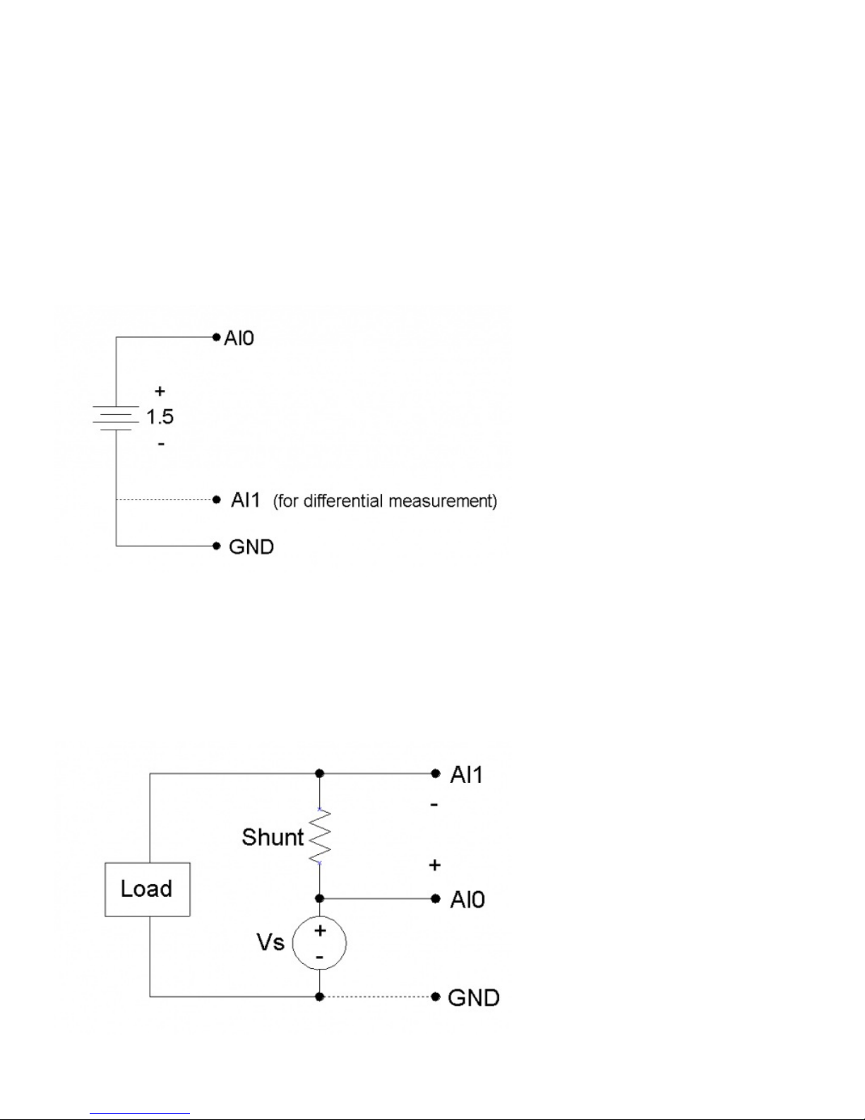
If improved accuracy is needed, measure the +5 volt supply with an analog input channel, and the actual output voltage can be
calculated. For instance, if an analog output of 2.5 volts is specified and a measurement of +5V returns 5.10 volts, the actual output
voltage is 2.55 volts (at no-load). Alternatively (and preferably), the analog output can itself be measured with an analog input.
There is a 1st order low-pass filter on each analog output with a 3dB frequency around 22 Hz.
The analog outputs are initialized to 0.0 volts on power-up or reset.
The analog outputs can withstand a continuous short-circuit to ground, even when set at maximum output.
Voltage should never be applied to the analog outputs, as they are voltage sources themselves. In the event that a voltage is
accidentally applied to either analog output, they do have protection against transient overvoltages such as ESD (electrostatic
discharge) and continuous overvoltage of a couple volts. An applied voltage that exceeds the capability of this protection will most
likely damage the resistor R63 (AO0) or R62 (AO1) on the LabJack U12 PCB. The symptom of such a failure would be reduced
voltage from the analog outputs, particularly at load, and could be verified by measuring the resistance of R62/R63 (should be less
than 50 ohms but a damaged resistor will measure higher). A simple repair for such damage is to remove the damaged resistor
and simply make a short with a blob of solder.
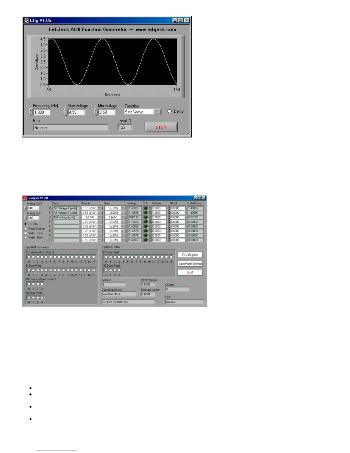
Software
The analog outputs are set using the function EAnalogOut (easy function) or AOUpdate, which take up to 20 ms to execute,
providing a maximum update rate of about 50 Hz per channel. AOUpdate also controls/reads all 20 digital I/O and the counter.
2.3 - IO0-IO3
Connections to 4 of the LabJack’s 20 digital I/O are made at the screw terminals, and are referred to as IO0-IO3. Each pin can
individually be set to input, output high, or output low. These 4 channels include a 1.5 kΩ series resistor that provides
overvoltage/short-circuit protection. Each channel also has a 1 MΩ resistor connected to ground.
All digital I/O are set to input on power-up or reset.
One common use of a digital input is for measuring the state of a switch as shown in Figure 2-5. If the switch is open, IO0 reads
FALSE. If the switch is closed, IO0 reads TRUE.
5

Figure 2-5. IO used to detect the state of a switch.
While providing overvoltage/short-circuit protection, the 1.5 kΩ series resistor on each IO pin also limits the output current
capability. For instance, with an output current of 1 mA, the series resistor will drop 1.5 volts, resulting in an output voltage of about
3.5 volts.
Software
The easy functions EDigitalIn or EDigitalOut are used to read or set the state of one digital line, and both take up to 20 ms to
execute.
The functions AOUpdate and DigitalIO are used to set the direction, set the state, and/or read the state, of each IO pin. Both of
these functions take up to 20 ms to execute, providing a maximum update rate of about 50 Hz per pin.
The function AISample can set/read the state of each IO, but setting the state will have no effect unless the IO have been
configured as outputs using another function. The function Counter reads the state of each IO.
The functions AIBurst and AIStreamRead, take a reading of the IO states and return it with the analog data. The states of the 4 IO
are read simultaneously every 4 samples, providing a data rate of up to 2048 Hz per pin for burst mode, or 300 Hz per pin for
stream mode. For 1 or 2 channel scans, duplicate data (4x or 2x) will be added to the read array such that the size is numScans.
2.4 - D0-D15
Connections to 16 of the LabJack’s 20 digital I/O are made at the DB25 connector, and are referred to as D0-D15. These 16 lines
have no overvoltage/short-circuit protection, and can sink or source up to 25 mA each (total sink or source current of 200 mA max
for all 16). This allows the D pins to be used to directly control some relays. All digital I/O are CMOS output and TTL input except
for D13-D15, which are Schmitt trigger input. Each D pin has a 1 MΩ resistor connected to ground.
All digital I/O are set to input on power-up or reset.
DB25 Pinouts:
1:
D0
6:
D5
11:
+5V
16:
GND
21:
D11
2:
D1
7:
D6
12:
+5V
17:
GND
22:
D12
3:
D2
8:
D7
13:
+5V
18:
D8
23:
D13
4:
D3
9:
NC
14:
GND
19:
D9
24:
D14
5:
D4
10:
+5V
15:
GND
20:
D10
25:
D15
These digital I/O can detect the state of a switch using the same circuit shown in Figure 2-5.
Because the D pins have no overvoltage/short-circuit protection, the user must be careful to avoid damage. A series
resistor can provide substantial protection for these pins (see the CB25 datasheet). The following are examples of
things that could damage a D pin and/or the entire LabJack:
6

Shorting a high output to ground (or any potential other than +5V).
Shorting a low output to a nonzero voltage (such as +5V).
Exceeding the voltage limits specified in Appendix A.
Software
The easy functions EDigitalIn or EDigitalOut are used to read or set the state of one digital line, and both take up to 20 ms to
execute.
The functions AOUpdate and DigitalIO are used to set the direction, set the state, and/or read the state, of each D pin. In addition,
DigitalIO also returns the current state of the direction and output registers. Both of these functions take up to 20 ms to execute,
providing a maximum update rate of about 50 Hz per pin.
2.5 - CNT
The input connection to the 32-bit counter is made at screw-terminal CNT. The counter is incremented when it detects a falling
edge followed by a rising edge. This means that if you reset the counter while your signal is low, you will not get the first count until it
goes high-low-high. In situations where this first count is important, you should simply substract the initial count from the final count,
rather than doing a reset.
Software
The functions ECount (easy function), AOUpdate, and Counter are used to reset or read the counter. If a reset is specified, the
counter is read first. All of these functions take up to 20 ms to execute, providing a maximum update rate of about 50 Hz.
Counter readings can also be returned in stream mode (AIStreamRead) at up to 300 Hz.
2.6 - CAL - STB
These terminals are primarily used at the factory during testing and calibration.
CAL is a precision 2.5 volt reference, and can be used during normal operation, but care should be taken to observe the current
limits specified in Appendix A. The CAL pin is protected from ESD and overvoltage, but severe overvoltage (steady-state or
transient) can damage CAL, and result in the failure of all analog inputs.
STB has 2 purposes. One is to disable the watchdog as described in Section 4.35, and the other is to create a rectangular output
signal for testing. For the latter, if the U12 is streaming the STB frequency matches the sampling frequency, while if not streaming
the STB frequency is about 28 kHz. To get this output signal on STB use the enableSTB parameter in the Counter function.
2.7 - +5V
The LabJack has a nominal +5 volt internal power supply. Power can be drawn from this power supply by connecting to the +5V
screw-terminals, or the +5V pins on the DB25 connector. The total amount of current that can be drawn from the +5V pins, analog
outputs, and digital outputs, is 450 mA for most desktop computers and self-powered USB hubs. Some notebook computers and
bus-powered hubs will limit this available current to about 50 mA.
The USB specification requires all hosts and hubs to have overcurrent protection. If the user puts too large a load on +5V
(including a short circuit of +5V to GND) of the LabJack U12 (a USB device), the host or hub is responsible for limiting the current.
2.8 - GND
The GND connections available at the screw-terminals and DB25 connector provide a common ground for all LabJack functions.
They are all the same.
Caution should be used whenever making connections with systems that have their own power source. It is normal to connect U12
ground to other grounds to create a common reference, but the risk is that the U12 ground will become the preferred ground for the
other systems and they could try to send high currents into the U12. To prevent this it is often a good idea to put a 10-100 ohm
resistor (or even a fuse) in series with GND on the U12 and any grounds from active systems.
2.9 - OEM Versions
7

The LabJack U12 is also available in 2 OEM (original equipment manufacturer) versions:
LJU12-PH: This is a populated LabJack U12 PCB with pin-headers installed (on the component side of the PCB) instead
of screw-terminals. Also, the LED is installed on the component side of the PCB, so nothing is installed on the solder side.
LJU12-NTH: This is a populated LabJack U12 PCB with no through-hole components (DB25 connector, USB connector,
LED, screw-terminals). This board is meant for OEMs who solder connections directly to the PCB, or wish to install only
certain connectors.
Dimensional drawings are available here.
Normally, nothing ships with these OEM LabJacks except for the populated PCB. All software is available online on the U12
Support Page.
3 - Example Applications
The LabJack U12 CD installs 9 example applications:
LJconfig: Lists all LabJacks connected to the USB and allows the local ID to be set on each.
LJcounter: Reads the LabJack counter and provides the current frequency or count.
LJfg (Function Generator): Outputs basic waveforms on AO0 (analog output zero).
LJlogger: Saves data to disk, writes data to an HTML page on the Internet, and performs various actions (including email) on
trigger events.
LJscope: Simulates an oscilloscope by reading data from 2 AI channels in burst mode.
LJstream: Uses stream mode to read, graph, and write to file, 4 AI channels.
LJtest: Runs a sequence of tests on the LabJack itself.
LJSHT: Retrieves and records data from 1 or 2 EI-1050 digital temperature/humidity probes.
LJSHTmulti: Displays data from up to 20 EI-1050 digital temperature/humidity probes.
The LabVIEW source code for most of these applications is installed in the examples directory.
3.1 - LJconfig
Every LabJack has a local ID and serial number. The local ID is a value between 0 and 255 that can be changed by the user. The
serial number is a value between 256 and 2,147,483,647 that is unique among all LabJacks and cannot be changed by the user.
LJconfig is used to set the local ID of a particular LabJack. When using multiple U12s, each should be assigned a unique local ID.
Figure 3-1. LJconfig
Figure 3-1 shows the window that opens when LJconfig is run. Each time the “Refresh” button is pushed, LJconfig will scan the
USB for all LabJacks. To change the local ID of a particular LabJack, push the “Change” button next to that LabJack, and the
8

window shown in Figure 3-2 will appear.
Figure 3-2. LJconfig Change Local ID
Enter a new local ID between 0 and 255 and push the “Change” button. The new local ID will be written and the LabJack will be
forced to re-enumerate.
3.2 - LJcounter
Reads the LabJack counter and provides the current frequency or count.
Figure 3-3. LJcounter
Figure 3-3 shows the LJcounter window:
Interval (seconds): Specifies the interval, in seconds, between calls to the DLL function “Counter”.
Measurement Type: If set to “Frequency”, this application divides the count by the interval to determine frequency in Hertz,
and automatically resets the counter every read. If set to “Count”, the measurement is simply the current reading from the
counter.
Measurement: Displays frequency or count, depending on “Measurement Type”.
3.3 - LJfg
This application allows the LabJack U12 to be used as a simple function generator. The DLL function “AOUpdate” is called every
25 milliseconds providing an update rate of 40 Hz, and thus a maximum reasonable signal frequency of a few Hertz.
9

Figure 3-4. LJfg
3.4 - LJlogger
LJlogger sends and receives data in command/response mode by making 2 DLL calls to “AISample” and 1 DLL call to
“AOUpdate”. It is capable of saving data to disk (2 Hz max) and performing various actions on trigger events.
Figure 3-5. LJlogger
The main window for LJlogger is shown in Figure 3-5. The white colored items and the “SDX” buttons are controls to be
edited/selected by the user. The grey colored items are indicators which display various information about the LabJack. Clicking
the button labeled “Save Panel Settings” will save the current values of the controls as the default values.
If SDX is activated for a given analog input, the corresponding SDX DLL will be used to determine the scaled data. Users can
make their own SDX DLLs (see the source code for more information), to provide more complex scaling or scaling that depends
on other analog inputs.
Clicking the “Configure” button shown in Figure 3-5 brings up the window shown in Figure 3-6:
Working Directory: This is the directory where data and configuration files will be written.
Data File Name: Determines the name of the data file to which data will be written. New data is appended to the end of this
file.
Data File Write Interval: Determines the interval at which a new row of data will be written to the data file. Minimum of 0.5
seconds.
HTML Write Interval: Determines the interval at which the HTML file is rewritten.
10

Figure 3-6. LJlogger Configuration
Clicking on the “Internet Setup” button in Figure 3-6 brings up the Internet configuration window shown in Figure 3-7. Basic
customization of the HTML file can be done by clicking on “Advanced HTML Configuration” which brings up Figure 3-8.
Clicking on the “Trigger Setup” button in Figure 3-6 brings up the window shown in Figure 3-9.
Figure 3-7. LJlogger Internet Configuration
11

Figure 3-8. LJlogger HTML Configuration
Figure 3-9. LJlogger Trigger Configuration
Figure 3-9 shows 9 example triggers:
Trigger #0: If the scaled data from analog input row 7 (Figure 3-5) is greater than 5, then set AO1 to 5 volts. Once triggered,
there is a 10 second delay before it can be triggered again.
Trigger #1: If IO3 is high, set IO2 high. Reset delay is zero so this trigger can occur every iteration (every 0.1 seconds) if IO3
is high.
Trigger #2: If D15 is low, set D14 low.
Trigger #3: If the count is greater than 10,000, set IO1 to an output.
Trigger #4: If it has been 3000 seconds since LJlogger started, set D13 to an output.
Trigger #5: When the PC’s clock is at 15 minute intervals, the status LED will be turned off and an email will be sent.
Trigger #6: Calls FunctionX from function1.dll. If the function returns True, reset the counter. Users can make their own
FunctionX DLLs. See the source code for more information.
Trigger #7: Calls FunctionX from function2.dll. If the function returns True, stop writing data to file.
Trigger #8: Calls FunctionX from function10.dll. If the function returns True, write 1 row to the data file.
3.5 - LJscope
LJscope simulates an oscilloscope by reading data from 2 analog input channels in burst mode.
Figure 3-10. LJscope
There are two graphs on the LJscope main window (Figure 3-10), which show voltage versus time and voltage versus frequency.
Both graphs have a palette to control various features such as autoscaling and zooming:
12

1. When you press this button it locks button 3 on (autoscale) position.
2. When you press this button it locks button 4 on (autoscale) position.
3. Pressing this button autoscales the x-axis.
4. Pressing this button autoscales the y-axis.
5. Miscellaneous x-axis formatting options.
6. Miscellaneous y-axis formatting options.
7. Zooming tool. Press this button to see different options for zooming. When collecting data, zooming will not work well unless
autoscaling is off.
8. Panning tool. Allows you to drag and scroll around the graph.
9. Not applicable.
Other LJscope controls include:
Channel A/B: Select the two AI channels that will be acquired. If a differential channel, is selected, the gain selection control
will appear.
Hide Channel B: When selected channel B will not be shown on the graph.
Scan Rate [Hz]: (256 to 4096) Determines the scans/second for both channels.
Number of Scans: (32 to 2048) Determines the number of scans that will be collected, and thus the total acquisition period.
For example, if 1024 scans are collected at 4096 Hz, a quarter second of data will be collected (as shown in Figure 3-10).
Demo: Calls “AIBurst” in demo mode so timing and data is simulated.
Save To Disk: If selected a prompt will appear for a filename, and the current burst of data is saved to a tab-delimited file
(time, channel A, channel B).
Pause: Pauses data acquisition.
Enable Trigger: Enables the IO trigger.
Configure Trigger: Brings up the window shown in Figure 3-11. Choose the IO line to trigger on and whether to trigger
when it is high or low. Also set the timeout period so the application will continue (with an error) if the trigger is not detected.
Figure 3-11. Configure Trigger
3.6 - LJstream
Uses stream mode to read, graph, and write to file, 4 AI channels. For more information, read about the stream functions
(AIStreamStart, AIStreamRead, and AIStreamClear).
Enable Stream: Starts and stops the stream acquisition.
Scan Rate: Determines the scans/second (50 to 300).
Number of Scans: Determines the number of scans that will be collected each iteration, and thus determines how fast this
application iterates.
Demo: Calls the “AIStream” functions in demo mode so timing and data is simulated.
Read Counter: Collects 1 analog input and the counter if selected.
Configure Channels: Click this button to bring up the channel configuration window shown in Figure 3-13.
Save Current Settings: Saves all the current settings, including channel configuration.
13

Graph History: Determines how much past history appears on the graph.
Figure 3-12. LJstream
Figure 3-13 shows the LJstream channel configuration window. Here you can select analog inputs and gains and enter scaling
equations. Use “Test Data” to see the effect of the scaling equations (“v” column is the measured voltage and the “y” column is the
output of the scaling equations). “Manual/Sampled” determines where the “Test Data” in the “v” column originates.
Figure 3-13. LJstream Channel Configuration
3.7 - LJtest
LJtest runs a sequence of tests on the LabJack itself. Users will generally leave “Test Fixture Installed” unselected and execute the
tests with nothing connected to the LabJack (except the USB of course).
Note that the U12 is not the “Test Fixture”. Rather, the U12 is the device under test (DUT) and might connect to a test fixture.
LJtest is installed as part of the normal U12 software package. It can typically be run by doing Start => Programs => LabJack U12
Legacy => Legacy U12 Samples => LJtest.
14

Figure 3-14. LJtest
If all tests fail except “OS Version” and “Driver Version”, it generally indicates LJtest does not detect a LabJack U12 at all. Check
for proper blinking of status LED upon power-up, and if using Windows 98 SE check out the related file (Win98sehid.zip) from the
downloads page at labjack.com.
If “Find LabJack” is the only failure, it is often because more than 1 LabJack U12 is connected.
“Check USB” performs some basic tests to detect any obvious problems with the Universal Serial Bus. Proper LabJack U12
communication is required for this test.
“Local ID” will show a yellow warning if the Local ID has been changed from the factory default of 0.
Failures from “Test RAM” or any of the “AI …” tests could indicate damage to the unit. Make sure there are no connections to the
LabJack U12 (except for the USB cable), and contact LabJack support if the failures continue. Yellow warnings on any of the “AI
…” tests (make sure nothing is connected to the AI channels) could indicate that a self-calibration needs to be performed (see
below).
A yellow warning from the “Cal Constants” test is usually because the constants have all been set to zero. Most often this is due to
selecting “Test Fixture Installed” and running LJtest without the proper connections. Follow the below procedure to correct this
issue.
To write new calibration data, a self-calibration should be performed using LJtest and 12 small (1.5” will work) jumper wires:
1. Make the following initial connections:
AI0 <=> AI2 <=> AI4 <=> AI6 <=> +5V
AI1 <=> AI3 <=> AI5 <=> AI7 <=> +5V
IO0 <=> IO1
IO2 <=> AO0
IO3 <=> AO1
CNT <=> STB
2. Start LJtest and select “Test Fixture Installed” and “Prompt During Cal”, and then click on the “Run” button.
3. LJtest will step through various tests and then prompt to connect GND to all 8 AI channels (AI6<=>GND and AI7<=>GND),
then to connect CAL to the even channels (AI6<=>CAL), then to connect CAL to all 8 AI channels (AI7<=>CAL), and finally to
connect GND to the even channels (AI6<=>GND).
4. When finished, remove all wires and unplug the USB cable. Reconnect the USB cable and the new calibration constants will
be loaded at power-up. Run LJtest again with “Test Fixture Installed” unselected, to make sure the unit passes the normal
self-test.
3.8 - LJSHT
15

Reads and records data from one or two EI-1050 digital temperature/humidity probes.
Figure 3-15. LJSHT
Figure 3-15 shows the LJSHT window:
Enabled (IO2/IO3): At least one EI-1050 must be connected. IO2 will be controlled as the enable line for this probe. If two
probes are connected, then enable control of IO3.
Force Software Communication: Forces software based SHT1X communication, even if the LabJack U12 firmware is
V1.10 or higher.
Write To File: Appends data to a tab-delimited ASCII file called ljsht.dat in the current directory. Data is written as seconds
since 1904, followed by tempC/tempF/RH for each probe.
3.9 - LJSHTmulti
Displays readings from up to 20 EI-1050 digital temperature/humidity probes connected to a single LabJack U12.
16

Figure 3-16. LJSHTmulti
Figure 3-16 shows the LJSHTmulti window:
Enable Line: Choose the LabJack U12 output used to control the enable line on each EI-1050 probe.
Force Software Communication: Forces software based SHT1X communication, even if the LabJack U12 firmware is
V1.10 or higher.
Enable Delay: Adds a delay between each reading for testing purposes.
4 - Programming Reference
The LabJack U12 CD installs high-level drivers (ljackuw.dll), an ActiveX interface to the high-level drivers (ljackuwx.ocx), and
LabVIEW6 (or higher) VIs which call all the DLL functions. The DLL and OCX are installed in the Windows System directory. If the
installation program can determine the LabVIEW directory, it copies the LabVIEW VIs into that directory (\vi.lib\addons\) so they
show up on the function palette. Otherwise, the LabVIEW drivers are copied into the LabJack installation directory (c:\Program
Files\LabJack)\drivers\labview, and can manually be transferred to the LabVIEW directory. LabVIEW5 VIs are also installed and
can be found in the \LabJack\examples directory.
There are 38 functions exported by the LabJack DLL, and matching functions in the OCX and LabVIEW VIs. There are two
additional support functions in the OCX, provided due to the limitations of ActiveX. All functions are command/response except for
AIBurst and AIStreamStart/Read/Clear.
There are 2 parameters that are used by most functions:
errorcode – A LabJack specific numeric error code. 0 means no error and 2 means no LabJacks were found. Use the
function “GetErrorString” to get a description of the error, or see the list in Section 4.24 of this document.
idnum – Functions with this input take either a local ID, serial number, or -1. A local ID or serial number will specify a specific
LabJack, while –1 means the first found LabJack. Every LabJack has a local ID and serial number. The local ID is a value
between 0 and 255 that can be changed by the user. The serial number is a value between 256 and 2,147,483,647 that is
unique among all LabJacks and cannot be changed by the user. When using multiple U12s, each should be assigned a
unique local ID.
To maintain compatibility with as many languages as possible, the every attempt has been made to keep the parameter types very
basic. The declarations that follow, are written in C. If there are any differences in the ActiveX version of a function, they are
described.
When a parameter name is preceded by a “*”, it means that it is a pointer. In most cases, this means that the parameter is an input
and/or output, whereas a non-pointer parameter is input only. In some cases a pointer points to an array of values rather than a
single value, and this will be noted in the parameter description.
Some of the digital I/O parameters contain the information for each bit of I/O in one value, where each bit of I/O corresponds to the
same bit in the parameter (i.e. the direction of D0 is set in bit 0 of parameter trisD). For instance, in the function DigitalIO, the
parameter *trisD is a pointer to a single memory location that sets/reads the direction of each of the 16 D lines:
if *trisD points to 0, all D lines are input,
if *trisD points to 1 (20), D0 is output, D1-D15 are input,
if *trisD points to 5 (20 + 22), D0 and D2 are output, all other D lines are input,
if *trisD points to 65535 (20 + … + 215), D0-D15 are output.
The range of the value pointed to by *trisD is 0 to 65535. When calling DigitalIO, if updateDigital is >1, the D lines will be set to
input or output based on the value pointed to by *trisD. When DigitalIO returns, the value pointed to by *trisD will have been set to
reflect the status of the direction register in the LabJack U12.
4.1 - EAnalogIn
Easy function. This is a simplified version of AISample. Reads the voltage from 1 analog input. Calling this function turns/leaves the
status LED on.
Execution time for this function is 20 milliseconds or less (typically 16 milliseconds in Windows).
Declaration:
long EAnalogIn ( long *idnum,
long demo,
long channel,
long gain,
17

long *overVoltage,
float *voltage )
Parameter Description:
Returns: LabJack errorcodes or 0 for no error.
Inputs:
*idnum – Local ID, serial number, or -1 for first found.
demo – Send 0 for normal operation, >0 for demo mode. Demo mode allows this function to be called without a LabJack.
channel – Channel command is 0-7 for single-ended, or 8-11 for differential.
gain – Gain command is 0=1, 1=2, …, 7=20. This amplification is only available for differential channels.
Outputs:
*idnum – Returns the local ID or -1 if no LabJack is found.
overVoltage – If >0, an overvoltage has been detected on one of the selected analog inputs.
voltage – Returns the voltage reading.
LabJackPython Example
>>> import u12
>>> d = u12.U12()
open called
Writing: [0x0, 0x0, 0x0, 0x0, 0x0, 0x57, 0x0, 0x0]
Received: [0x57, 0x0, 0x0, 0x0, 0xff, 0xff, 0x0, 0x0]
>>> d.eAnalogIn(0)
Writing: [0x8, 0x9, 0xa, 0xb, 0x1, 0xc0, 0x0, 0x0]
Received: [0x85, 0x0, 0x99, 0x2b, 0x2b, 0x99, 0x2c, 0x26]
{'overVoltage': 0, 'idnum': 12, 'voltage': 1.4599609375}
4.2 - EAnalogOut
Easy function. This is a simplified version of AOUpdate. Sets the voltage of both analog outputs.
Execution time for this function is 20 milliseconds or less (typically 16 milliseconds in Windows).
If either passed voltage is less than zero, the DLL uses the last set voltage. This provides a way to update 1 output without
changing the other. Note that when the DLL is first loaded, it does not know if the analog outputs have been set, and assumes they
are both the default of 0.0 volts. Similarly, there are situations where the LabJack could reset without the knowledge of the DLL,
and thus the DLL could think the analog outputs are set to a non-zero voltage when in fact they have been reinitialized to 0.0 volts.
Declaration:
long EAnalogOut ( long *idnum,
long demo,
float analogOut0,
float analogOut1 )
Parameter Description:
Returns: LabJack errorcodes or 0 for no error.
Inputs:
*idnum – Local ID, serial number, or -1 for first found.
demo – Send 0 for normal operation, >0 for demo mode. Demo mode allows this function to be called without a LabJack.
analogOut0 – Voltage from 0.0 to 5.0 for AO0.
analogOut1 – Voltage from 0.0 to 5.0 for AO1.
Outputs:
*idnum – Returns the local ID or –1 if no LabJack is found.
LabJackPython Example
>>> import u12
>>> d = u12.U12()
open called
Writing: [0x0, 0x0, 0x0, 0x0, 0x0, 0x57, 0x0, 0x0]
18

Received: [0x57, 0x0, 0x0, 0x0, 0xff, 0xff, 0x0, 0x0]
>>> d.eAnalogOut(2, 2)
Writing: [0x0, 0x0, 0x0, 0x0, 0x0, 0x5, 0x66, 0x66]
Received: [0x0, 0x0, 0x0, 0x50, 0xbb, 0x10, 0x0, 0xef]
{'idnum': 12}
4.3 - ECount
Easy function. This is a simplified version of Counter. Reads & resets the counter (CNT). Calling this function disables STB (which
is the default anyway).
Execution time for this function is 20 milliseconds or less (typically 16 milliseconds in Windows).
Declaration:
long ECount ( long *idnum,
long demo,
long resetCounter,
double *count,
double *ms )
Parameter Description:
Returns: LabJack errorcodes or 0 for no error.
Inputs:
*idnum – Local ID, serial number, or -1 for first found.
demo – Send 0 for normal operation, >0 for demo mode. Demo mode allows this function to be called without a LabJack.
resetCounter – If >0, the counter is reset to zero after being read.
Outputs:
*idnum – Returns the local ID or –1 if no LabJack is found.
*count – Current count, before reset.
*ms – Value of Window’s millisecond timer at the time of the counter read (within a few ms). Note that the millisecond timer
rolls over about every 50 days. In general, the millisecond timer starts counting from zero whenever the computer reboots.
LabJackPython Example
>>> import u12
>>> d = u12.U12()
open called
Writing: [0x0, 0x0, 0x0, 0x0, 0x0, 0x57, 0x0, 0x0]
Received: [0x57, 0x0, 0x0, 0x0, 0xff, 0xff, 0x0, 0x0]
>>> d.eCount()
Writing: [0x0, 0x0, 0x0, 0x0, 0x0, 0x52, 0x0, 0x0]
Received: [0x52, 0x0, 0x0, 0x50, 0xbb, 0x10, 0x0, 0xef]
{'count': 3138388207, 'idnum': 12, 'ms': 1273175001372.4438}
4.4 - EDigitalIn
Easy function. This is a simplified version of DigitalIO that reads the state of one digital input. Also configures the requested pin to
input and leaves it that way.
Execution time for this function is 20 milliseconds or less (typically 16 milliseconds in Windows).
Note that this is a simplified version of the lower level function DigitalIO, which operates on all 20 digital lines. The DLL (ljackuw)
attempts to keep track of the current direction and output state of all lines, so that this easy function can operate on a single line
without changing the others. When the DLL is first loaded, though, it does not know the direction and state of the lines and
assumes all directions are input and output states are low.
Declaration:
long EDigitalIn ( long *idnum,
long demo,
long channel,
long readD,
19

long *state )
Parameter Description:
Returns: LabJack errorcodes or 0 for no error.
Inputs:
*idnum – Local ID, serial number, or -1 for first found.
demo – Send 0 for normal operation, >0 for demo mode. Demo mode allows this function to be called without a LabJack.
channel – Line to read. 0-3 for IO or 0-15 for D.
readD – If >0, a D line is read as opposed to an IO line.
Outputs:
*idnum – Returns the local ID or –1 if no LabJack is found.
*state – The selected line is TRUE/Set if >0. FALSE/Clear if 0.
LabJackPython Example
>>> import u12
>>> d = u12.U12()
open called
Writing: [0x0, 0x0, 0x0, 0x0, 0x0, 0x57, 0x0, 0x0]
Received: [0x57, 0x0, 0x0, 0x0, 0xff, 0xff, 0x0, 0x0]
>>> d.eDigitalIn(0)
Writing: [0x0, 0x0, 0x0, 0x0, 0x0, 0x57, 0x0, 0x0]
Received: [0x57, 0x0, 0x0, 0x50, 0xff, 0xff, 0x0, 0x0]
Writing: [0x0, 0x0, 0x0, 0x0, 0xff, 0x57, 0x1, 0x0]
Received: [0x57, 0x0, 0x0, 0x50, 0x0, 0x0, 0x0, 0x0]
{'state': 1, 'idnum': 12}
4.5 - EDigitalOut
Easy function. This is a simplified version of DigitalIO that sets/clears the state of one digital output. Also configures the requested
pin to output and leaves it that way.
Execution time for this function is 20 milliseconds or less (typically 16 milliseconds in Windows).
Note that this is a simplified version of the lower level function DigitalIO, which operates on all 20 digital lines. The DLL (ljackuw)
attempts to keep track of the current direction and output state of all lines, so that this easy function can operate on a single line
without changing the others. When the DLL is first loaded, though, it does not know the direction and state of the lines and
assumes all directions are input and output states are low.
Declaration:
long EDigitalOut ( long *idnum,
long demo,
long channel,
long writeD,
long state )
Parameter Description:
Returns: LabJack errorcodes or 0 for no error.
Inputs:
*idnum – Local ID, serial number, or -1 for first found.
demo – Send 0 for normal operation, >0 for demo mode. Demo mode allows this function to be called without a LabJack.
channel – Line to read. 0-3 for IO or 0-15 for D.
writeD – If >0, a D line is written as opposed to an IO line.
state – If >0, the line is set, otherwise the line is cleared.
Outputs:
*idnum – Returns the local ID or –1 if no LabJack is found.
LabJackPython Example
>>> import u12
20
Other manuals for U12
3
Table of contents
Popular Test Equipment manuals by other brands

Anritsu
Anritsu BERTWave MP2100B Operation manual

Agilent Technologies
Agilent Technologies Medalist i3070 Series 5i manual

JDS Uniphase
JDS Uniphase IP Video Test Option HST-3000 user guide

Solmetric
Solmetric PVA-1000S Quick reference card

AOIP
AOIP CALYS 1500 instruction manual

FUTABA
FUTABA BR-3000 instruction manual