Labnet VorTemp 56 User manual

Labnet VorTemp™ 56 Shaking Incubator
Instruction Manual
Catalog Numbers:
S2056A
S2056A-230V

Table of Contents
1.0 Introduction....................................................................................1
1.1 Symbols and Conventions ...................................................................1
2.0 Packing ........................................................................................1
3.0 Specifications ..................................................................................1
3.1. Construction...............................................................................2
3.2. Main Components .........................................................................2
4.0 Accessories.....................................................................................2
4.1. Microcentrifuge Tube Platform..............................................................2
4.2. Microplate Holder Platform.................................................................3
5.0 Safety Information .............................................................................4
6.0 Installation.....................................................................................4
6.1. Device Placement ..........................................................................4
6.2. Attaching the Power Cord ..................................................................4
6.3. Start Up Check List .........................................................................4
7.0 Operating Instructions ..........................................................................5
7.1. Control Panel ..............................................................................5
7.2. Basic Operation ............................................................................5
7.3. Shaking Without Heating...................................................................7
7.4. Heating Without Shaking...................................................................7
7.5. Additional Operations ......................................................................8
8.0 Troubleshooting ................................................................................8
9.0 Temperature Calibration ........................................................................8
10.0 Maintenance and Cleaning......................................................................9
11.0 Limited Warranty ...............................................................................9
12.0 Equipment Disposal .......................................................................... 10

Instruction Manual | 1
1.0 Introduction
The Labnet VorTemp™ 56 shaking incubator is a benchtop shaker and heating chamber for incubating and shaking sensitive samples.
It replaces two devices, reducing both time and space needed. It is suitable for biochemistry, microbiology, and clinical laboratories in
which applications require temperature and shaking treatment.
1.1 Symbols and Conventions
CAUTION: This symbol refers you to important operating and maintenance (servicing) instructions within the product
Instruction Manual. Failure to heed this information may present a risk of damage or injury to persons or equipment.
CAUTION: To avoid accidental bodily harming or burning be very careful touching the metal parts of the unit. It can be
very hot after it is used at high temperatures. Allow the metal parts to cool down before handling.
This symbol indicates the presence of a potential hazard which could result in electrical shock.
2.0 Packing
The Labnet VorTemp 56 shaking incubator includes the following components:
VorTemp 56 shaking incubator (platforms sold separately)
Instruction manual
3.0 Specications
Power 515W
Heater Power 500W
Motor Power 15W
Electrical
S2056A
S2056A-230V
120V ±10%, 50/60Hz, 4.8A
230V ±10%, 50/60Hz, 2.4A
Fuse
S2056A
S2056A-230V
2 x T 6.3A L 250V
2 x T 3.15A L 250V
Environmental Temperature From 5°C to 40°C
Relative Humidity Up to 85% non-condensing
RPM Regulation Digital load independent, from 100 to 1,200 rpm in 10 rpm steps, 1,400 rpm (only at 60Hz)
Shaker Orbit 3 mm
Temperature Operating Range From 5°C above room temperature to 99.5°C
Temperature Sensor PT100
Heat up Time Approx. 5°C/min.
Temperature Uniformity ±0.5°C
Timer From 30 sec. to 99 min. 50 sec. in 10 sec. steps, under 10 min. in 1 sec. steps, timer HOLD function
Maximum Capacity 56 test tubes – 1.5, 0.7, 0.5, 0.25 mL
Dimensions (W x D x H) 10 x 13 x 9 in. (26.5 x 32.5 x 22.5 cm)
Weight 24 lbs. (11 kg)
NOTE: The supply cord shall be with PE conductor and cross section at least 3 x 1.00 mm2or 3 x AWG 18 (USA/CANADA).
Labnet VorTemp 56 shaking incubator is designed to be safe when operated under the following conditions:
Indoor use
Altitude up to 2,000 meters
Pollution Degree 2
Unit can be connected to external installation with overcurrent protective device max. value 16A or 20A (USA/CANADA). This device
is intended for use in a basic electromagnetic environment (Basic, class B), and it is in compliance with IEC 61326-1:2020. Device may
experience a restart during overvoltage events (surges) or voltage interruptions in mains power supply.

2| LABNET VORTEMP 56 SHAKING INCUBATOR
3.1. Construction
The housing of Labnet VorTemp™ 56 shaking incubator is constructed of steel plate coated with highly resistant polyurethane lacquer.
The interior chamber is isolated with special thermal protection materials and insulation foam. Both the shaking mechanism and
temperature chamber regulated via microprocessors, which control all sensors for motor speed, temperature, and time.
3.2. Main Components
Drive motor
Eccentricity control mechanism chamber
Fan
Heating element
Temperature sensor
Temperature controlled chamber control
Electronics
The motor drives the eccentricity control mechanism chamber which generates the orbital motion of the sample platform.
The motion of the motor also drives the fan, which moves air over the heating element and throughout the temperature chamber. The
convection action of the airflow creates a very uniform temperature environment throughout the chamber. Chamber conditions are
monitored by the temperature sensor and the control electronics regulate heater function to maintain the set temperature.
4.0 Accessories
Cat. No. Description Qty/Pk
S2056-R 1.5/2.0 mL platform/workstation for microcentrifuge tubes 1
S2056-Q Microplate platform 1
C1205 Individual adapters for 0.5/0.6 mL tubes 6
C1206 Individual adapters for 0.4 mL tubes 6
C1222 Individual adapters for 0.2 mL thermal cycling tubes 6
4.1. Microcentrifuge Tube Platform
The Microcentrifuge Tube Platform is intended for shaking 56 x 1.5/2 mL test tubes. There are accessory adapters available which
allow for running several different microcentrifuge tube sizes. In addition, the platform and adapters are autoclavable.
Screw
Shaking plate
(in shield chamber)
Installing the microcentrifuge tube platform is very simple and requires no special tools. The unit comes pre-assembled with four posts
screwed into the shield plate. Grip the microcentrifuge tube platform by the center knob and align the four rubber grommets with the
four posts of the platform and press down gently.
For processing large sample quantities it is often more convenient to use more than one microcentrifuge tube platform and switch
between them.

Instruction Manual | 3
NOTE: If you work with temperatures over 50°C, we recommend the use of special microcentrifuge tubes which are designed for
use in thermal cyclers. These tubes are molded from plastic designed to withstand temperatures as high as 135°C. The thin-walled
construction also allows for fast heat transfer and reduced heating times.
4.2. Microplate Holder Platform
CAUTION: Be careful if the unit has been used to heat samples because the internal components can be extremely hot
and can cause burns to uncovered skin. Always check the handle temperature before changing the platform.
The Microplate Holder Platform is designed for shaking up to 4 microplates or 2 deepwell microplates. For a more precise temperature
controlled environment we recommend inserting only one microplate on the platform. Additional microplates can have an insulating
effect on other plates, especially when stacked. The working temperature range is ambient from +5°C to 40°C. Please note that the
normal maximum temperature for ordinary microplates is below 60°C. The platform is made of stainless steel and is equipped with
springs for keeping microplates secure.
The Labnet VorTemp™ 56 shaking incubator comes with the microcentrifuge tube platform installed. To install the microplate
platform, first you have to remove the microcentrifuge tube platform, and then unscrew all four posts from the lower platform.
To attach the microplate platform (see the below picture), you must center the platform corner holes with the device shield plate.
Make sure the alignment arrows are pointing towards the front of the unit, and then press the platform on the shield plate. Take the
supplied nuts and washers and screw them on to the microplate platform, and tighten them with the included wrench. Insert the
microplates with your samples, and start the device.
Screw Unscrew
NOTE: When you attach the microplate platform, it must be attached so that the arrows are pointed towards the front of VorTemp 56
shaking incubator.

4| LABNET VORTEMP 56 SHAKING INCUBATOR
5.0 Safety Information
NOTE: Be careful when changing the microcentrifuge tube platform, especially when you have used the unit at
temperatures higher than 60°C. Always wear protective clothing before you handle a hot platform.
The unit will continue to shake for 5 seconds after the lid is opened. Be careful when opening the lid as the parts inside
may still be in motion. In addition, never touch the fan unless the unit is turned off or unplugged.
If the equipment is used in a manner not specified by the manufacturer, the protection provided by the equipment may be impaired.
Before cleaning the housing unplug the unit. The housing should only be cleaned with a damp cloth and if necessary, a mild soap.
Don’t use aggressive or aerosol cleaners.
Do not use the unit near sources of water. Take care to ensure that water will not spill in the device, especially during cleaning
procedures.
Make sure, that all test tubes are closed tightly before placing them into the unit to avoid spilling samples inside the chamber.
In the case of a malfunction, unplug the device and contact your distributor for service.
Do not shake flammable or explosive samples.
6.0 Installation
6.1. Device Placement
Do not use the device in a flammable or explosive atmosphere.
NOTE: There has to be easy access to the incubator control panel and main plug in case of emergency.
When selecting the right place for device, please consider following:
Put the device on a smooth, horizontal, and stable place.
Leave at least 10 cm of space around the device for adequate air circulation.
Leave enough space around the device, for easy access and maintenance.
Do not place the device where there are rapid temperature and humidity changes. Also avoid places where the unit would be exposed to
direct sunlight or next to devices that output large amounts of heat.
Avoid locations where the unit may be exposed to excessive shocks or vibrations.
Avoid locations subject to frequent power fluctuations or power losses.
6.2. Attaching the Power Cord
First, connect the main power cord to the incubator, then connect the plug end of the cord to a grounded wall socket. Avoid lines on
which powerful electric motors, refrigerators, and similar devices are connected.
Always use caution when plugging the cord into a grounded power outlet.
Do not touch the plug with wet hands.
Do not pull the plug by the cord.
6.3. Start Up Check List
Unpack and install the device as specified in Sections 6.1 and 6.2.
Open the lid and attach the microcentrifuge tube platform or the microplate holder platform.
Close the lid.
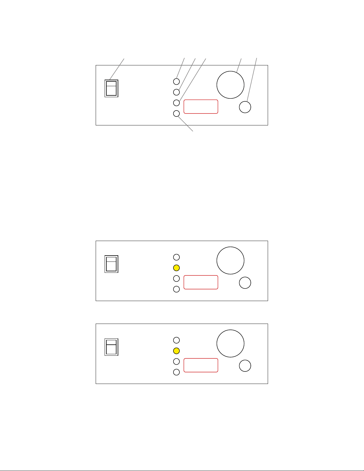
Switch on the device using of the ON/OFF switch on the front panel. The switch will illuminate to indicate that the power is On.
Check the running parameters, and set new parameters if necessary. Refer to the instructions described in Section 7.

Instruction Manual | 5
7.0 Operating Instructions
7.1. Control Panel
88.8 Stop
Encoder
Power
Run
Time [min]
RPM [x10]
Temp [°C]
1 2 3 4 6 7
5
Start
1. Power Key: Switch ON (illuminates when on) or OFF.
2. Run: Green signal light illuminated when the shaker is operating.
3. Time: Yellow signal light illuminated when the unit is set to adjust time.
4. RPM: Yellow signal light illuminated when the unit is set to adjust RPM.
5. Temperature: Yellow signal light illuminated when incubator is set to adjust the set temperature.
6. Encoder Knob: Rotate the encoder right (+) or left (-) to modify the Time, Temperature, or RPM settings. Push in the Encoder knob to
change between Time, Temperature, and RPM set values. If you rotate the Encoder knob quickly, then the adjustment increments
are larger and it will allow for values to be set more quickly.
7. Start/Stop Button: Start or stop shaking.
7.2. Basic Operation
Press the Power Key on the control panel. On the LED display the unit will automatically detect the line frequency F50 (50Hz) or F60 (60Hz).
F50 Stop
Encoder
Power
Run
Time [min]
RPM [x10]
Temp [°C]
Start
After a 2-second delay the unit will then default to the Time setting.
99.5 Stop
Encoder
Power
Run
Time [min]
RPM [x10]
Temp [°C]
Start

6| LABNET VORTEMP 56 SHAKING INCUBATOR
Time Illuminated
Rotating the Encoder knob, right (+) or left (-) sets the run time to the desire value from 30 sec. to 99 min. 50 sec.:
99.5 = 99 min. 50 sec.
9.59 = 9 min. 59 sec.
0.30 = 30 sec.
If you want the unit to run continuously, set Time on hold. The timer is set to hold when HLd is displayed. Rotate the Encoder knob
under 0.30 or above 99.5 to set this hold function.
Push the Encoder knob to adjust the RPM setting.
34 Stop
Encoder
Power
Run
Time [min]
RPM [x10]
Temp [°C]
Start
RPM Illuminated
Rotating the encoder right (+) or left (-) sets the rotating speed to the desired value:
34 = 340 rpm
90 = 900 rpm
By turning the RPM setting below 20, the shaking function can be turned off. When the shaker is off, OFF is displayed.
OFF Stop
Encoder
Power
Run
Time [min]
RPM [x10]
Temp [°C]
Start
Push the Encoder knob to adjust the Temperature setting.
37.4 Stop
Encoder
Power
Run
Time [min]
RPM [x10]
Temp [°C]
Start
Temperature Illuminated
Rotating the Encoder knob right (+) or left (-) sets the temperature to the desired value:
37.4 = 37.4°C
If you want to use the incubator without temperature control activated, turn the Encoder knob under 0.5 or above 99.5 until the
display reads OFF.

Instruction Manual | 7
Pressing the Start/Stop Button
Run and Time are illuminated. The timer will count down from the set time value.
NOTE: You cannot adjust the set time during shaking.
99.4 Stop
Encoder
Power
Run
Time [min]
RPM [x10]
Temp [°C]
Start
RMP Adjusting During a Run
Push the Encoder knob until the RPM light is illuminated.
Rotate the encoder right (+) or left (-) until the new value is set. While adjusting the RPM, the light will blink.
When you stop rotating the encoder knob, the RPM light will stop blinking after 2 sec.
l
l
l
l
l
l
l
l
l
100 Stop
Encoder
Power
Run
Time [min]
RPM [x10]
Temp [°C]
Start
Temperature Adjusting During a Run
Push the Encoder Knob until the RPM light is illuminated.
Rotate the encoder right (+) or left (-) until the new value is set. While adjusting the RPM, the light will pulse.
When you stop rotating the encoder knob, the RPM light will stop blinking after 2 sec.
l
l
l
l
l
l
l
l
l
37.0 Stop
Encoder
Power
Run
Time [min]
RPM [x10]
Temp [°C]
Start
When the set time expires or if you press the Start/Stop button, End will be displayed and the Run light will blink. When the unit
stops shaking, the last set values for Time, RPM, and Temp will be saved in memory.
7.3. Shaking Without Heating
If you want to shake samples without heating, set Temp to OFF.
7.4. Heating Without Shaking
If you want to heat samples without shaking, set RPM to OFF.
NOTE: The shaker motor drives the fan, which circulates warm air throughout the chamber aiding in temperature uniformity. If
the RPM is set to OFF, the temperature control will not be as precise due to lack of airflow over the heating element. Maximum set
temperature in this program is 70°C.

8| LABNET VORTEMP 56 SHAKING INCUBATOR
7.5. Additional Operations
Viewing the set value for RPM during shaking
Set the unit to RPM mode
Turn the encoder ONE CLICK right (+) or left (-). On the display the RPM light will blink for 2 sec. and will display the set RPM. After
2 sec. the display will show the actual RPM and the light will stop blinking.
Viewing the set value for Time during shaking
Set the unit to Time Mode
Turn the encoder ONE CLICK right (+) or left (-). The Time light will blink for 2 sec. and will display the set Time. After 2 sec. the
display will show the actual Time and the light will stop blinking.
Viewing the set value for Temperature during shaking
Set the unit to Temperature Mode
Turn the encoder ONE CLICK right (+) or left (-). The Temperature light will blink for 2 sec. and will display the set Temperature. After
2 sec. the display will show the actual Temperature and the light will stop blinking.
8.0 Troubleshooting
The Labnet VorTemp™ 56 shaking incubator features built in self-diagnostic procedures which are constantly checking the operating
parameters and performance, as well as functions that are necessary for safe and reliable operation. An error code is shown on the
LCD display if an error occurs.
Sample of Error display:
Er5 Stop
Encoder
Power
Run
Time [min]
RPM [x10]
Temp [°C]
Start
E 1.1 Something is wrong with the motor regulation (PWM regulator, pulse generator, motor). The unit will automatically stop.
Call for service.
E 1.2 The motor does not reach the set RPM in 30 sec. The unit will automatically stop. Call for service.
E 1.3 The set RPM oscillates more than 100 RPM in 2 seconds. The unit will automatically stop. Call for service.
E 2.1 The temperature sensor is not working properly with regards to the heater. The unit will automatically stop. Call for service.
E 2.2 The temperature sensor registers a 5°C higher temperature than the set temperature. The unit will automatically stop.
Call for service.
Er 5 The lid of the shaker is opened for more than 5 seconds. The unit will automatically stop. To restart the shaker, close the lid
and press Start.
When shipping your equipment for service, follow the packing guidelines listed below:
Clean the inside of the chamber and platforms according to GLP (Good Laboratory Practices) standards, especially if you have used
the equipment with hazardous biological or radioactive materials.
A written description of the error should accompany the unit.
Use the original shipping container and packaging materials if possible.
9.0 Temperature Calibration
NOTE: Temperature calibration should only be performed by qualified personnel.
The temperature control software allows for user calibration of the temperature settings. First, measure the temperature in the
middle of the chamber after allowing the temperature to equilibrate for 2 hours. The temperature should be measured with a digital

Instruction Manual | 9
calibrated thermometer with precision 0.1°C or more. After allowing the temperature to equilibrate for 2 hours, read the temperature
on the thermometer and compare it with the temperature on the LED display. This difference between the thermometer and the
display is the value which you will enter into the unit to recalibrate it.
Example 1: Temperature on the thermometer is 37.9°C, temperature on display is 37°C.
The difference is 37.9 - 37 = 0.9. This value 0.9, is the value which you will enter into the software.
Example 2: Temperature on the thermometer is 36.2°C, temperature on display is 37°C.
The difference is 37 - 36.2 = -0.8. This value -0.8, is the value which you will enter into the software.
Procedure for temperature calibration:
1. Hold (press) the encoder for 5 seconds – the display then show Cor (correction).
2. Press the encoder once and then enter the value from the previous section by rotating the encoder left or right to select a value (see
Example 1 and Example 2 above). Be sure to note whether your value was positive or negative. After you have entered the value,
press the encoder again.
3. Press the Start/Stop button to complete the temperature calibration.
10.0 Maintenance and Cleaning
Before you begin cleaning the unit, be sure to unplug the unit. Before using any cleaning or decontamination methods other than
those recommended by the manufacturer, contact Corning to check that the proposed method will not damage the equipment.
The chamber should be cleaned regularly. Any samples which spill inside or outside the chamber must be wiped up immediately. Use
only warm water or a mild soap solution to clean the surfaces of the unit. Using aggressive or abrasive cleaners can cause permanent
damage to the finish.
To decontaminate the surface of the unit, use only neutral solutions (pH 7-8). The stainless steel platform and nuts can be
decontaminated with autoclave (120°C).
NOTE: Take care when cleaning the device after operation, especially when you have used the device at temperatures higher than
60°C. Exposed surfaces will be extremely hot and may cause burns to unprotected skin.
11.0 Limited Warranty
Corning Incorporated (Corning) warrants that this product will be free from defects in material and workmanship for a period of
one (1) year from date of purchase. CORNING DISCLAIMS ALL OTHER WARRANTIES WHETHER EXPRESSED OR IMPLIED, INCLUDING
ANY IMPLIED WARRANTIES OF MERCHANTABILITY OR OF FITNESS FOR A PARTICULAR PURPOSE. Corning’s sole obligation shall be to
repair or replace, at its option, any product or part thereof that proves defective in material or workmanship within the warranty
period, provided the purchaser notifies Corning of any such defect. Corning is not liable for any incidental or consequential damages,
commercial loss or any other damages from the use of this product.
This warranty is valid only if the product is used for its intended purpose and within the guidelines specified in the supplied instruction
manual. This warranty does not cover damage caused by accident, neglect, misuse, improper service, natural forces or other causes not
arising from defects in original material or workmanship. This warranty does not cover motor brushes, fuses, light bulbs, batteries or
damage to paint or finish. Claims for transit damage should be filed with the transportation carrier.
In the event this product fails within the specified period of time because of a defect in material or workmanship, contact Corning
Customer Service at: USA/Canada 1.800.492.1110, outside the U.S. +1.978.442.2200, visit www.corning.com/lifesciences, or contact
your local support office.
Corning’s Customer Service team will help arrange local service where available or coordinate a return authorization number and
shipping instructions. Products received without proper authorization will be returned. All items returned for service should be sent
postage prepaid in the original packaging or other suitable carton, padded to avoid damage. Corning will not be responsible for
damage incurred by improper packaging. Corning may elect for onsite service for larger equipment.
Some states do not allow limitation on the length of implied warranties or the exclusion or limitation of incidental or consequential
damages. This warranty gives you specific legal rights. You may have other rights which vary from state to state.
No individual may accept for, or on behalf of Corning, any other obligation of liability, or extend the period of this warranty.
For your reference, make a note of the serial and model number, date of purchase, and supplier here.
Serial No. ______________________________________ Date Purchased _______________________________________
Model No. _____________________________________ Supplier _____________________________________________

12.0 Equipment Disposal
According to Directive 2012/19/EU of the European Parliament and of the Council of 4 July 2012 on waste electrical and
electronic equipment (WEEE), this product is marked with the crossed-out wheeled bin and must not be disposed of with
domestic waste.
Consequently, the buyer shall follow the instructions for reuse and recycling of waste electronic and electrical equipment
(WEEE) provided with the products and available at www.corning.com/weee.
www.labnetlink.com
For a listing of trademarks, visit www.corning.com/clstrademarks. All other trademarks are the property of their respective owners.
© 2021, 2022 Corning Incorporated. All rights reserved. 12/22 CLSLN-AN-1019DOC REV2
Corning Incorporated
Life Sciences
www.corning.com/lifesciences
NORTH AMERICA
t 800.492.1110
t 978.442.2200
ASIA/PACIFIC
Australia/New Zealand
t 61 427286832
Chinese Mainland
t 86 21 3338 4338
India
t 91 124 4604000
Japan
t 81 3-3586 1996
Korea
t 82 2-796-9500
Singapore
t 65 6572-9740
Taiwan
t 886 2-2716-0338
EUROPE
LATIN AMERICA
Brazil
t 55 (11) 3089-7400
Mexico
t (52-81) 8158-8400
To request certificates, please contact us at www.labnetlink.com.
Warranty/Disclaimer: Unless otherwise specified, all products are for research use or general laboratory use only.* Not intended for
use in diagnostic or therapeutic procedures. Not for use in humans. These products are not intended to mitigate the presence of
microorganisms on surfaces or in the environment, where such organisms can be deleterious to humans or the environment. Corning
Life Sciences makes no claims regarding the performance of these products for clinical or diagnostic applications. *For a listing of US
medical devices, regulatory classifications or specific information on claims, visit www.corning.com/resources.
Other manuals for VorTemp 56
1
This manual suits for next models
2
Table of contents
Other Labnet Accessories manuals

Labnet
Labnet 311D Quick guide

Labnet
Labnet VorTemp 1550 User manual

Labnet
Labnet VorTemp 56 User manual

Labnet
Labnet I5110 User manual

Labnet
Labnet 222DS User manual

Labnet
Labnet 211DS User manual

Labnet
Labnet Accublock D1301-230V User manual

Labnet
Labnet I-4001-HCS User manual

Labnet
Labnet I-5222-DS User manual

Labnet
Labnet I5110A User manual
Popular Accessories manuals by other brands

Atim Cloud Wireless
Atim Cloud Wireless ACW/SF8-THM-I user guide

A&D
A&D FS-D Setup instructions

Atom Longboards
Atom Longboards Atom Electric B Series owner's manual

FedEx
FedEx SenseAware PT300D quick start guide

MobilePal
MobilePal Qi user manual

ROSE DISPLAYS
ROSE DISPLAYS ANOSKYBOX-TOP LOADING 4 WAY manual