B&K CT1 User manual

B&K Components, Ltd.
CT-1
User Manual
IR Routing System Integrator
For use with
CT Multi-Zone Receivers
and
Home Theater Systems
13475 0504C

USER MANUAL - CT-1
© 2004 B & K Components Ltd. All rights reserved.
The information in this manual is copyright protected. No part of this manual may be copied or reproduced in
any form without prior written consent from B&K Components, Ltd.
B & K Components Ltd. SHALL NOT BE LIABLE FOR OPERATIONAL, TECHNICAL OR EDITORIAL
ERRORS/OMISSIONS MADE IN THIS MANUAL.
The information in this manual may be subject to change without prior notice.
SIMPLY BETTER! is a registered trademark of B & K Components, Ltd. All other brand or product names are
trademarks or registered trademarks of their respective companies or organizations.
B & K Components, Ltd. sells its products through authorized dealers. Buying from an authorized B & K
Components, Ltd. dealer insures that you have a FACTORY WARRANTY on your B & K Components, Ltd.
product. A warranty on B & K Components, Ltd. products is NOT VALID if the products have been purchased
from an unauthorized dealer, an E-tailer or if the factory serial number has been removed, defaced or
replaced in any way.
Accessories Included
1 - CT-1
1 - CT-1 User Manual
1 - Warranty Card
B & K Components, Ltd.
2100 Old Union Road
Buffalo, New York 14227
1.800.543.5252 In NY: 716.656.0026
Fax: 716.656.1291
E-mail: [email protected]
www.bkcomp.com
SBIMPLY ETTER!
BK&

Table of Contents
Table of Contents
1
Table of Contents 1
Introduction / Overview 2
Safety Precautions 3
CT-1 Back Panel 4
Input / Output Diagram 5
CT-1 Back Panel 5
Single CT-1 Basic Connection 6
CT-1 Source Connection 7
Connecting a Home Theater Product 8
Multiple CT-1 Chaining 10

The CT-1 IR integrator is the keystone to any multi-CT Receiver install. A single CT-1 can integrate control
for up to three CT Receivers, one B&K Home Theater preamplifier/receiver, nine shared sources and one
CK1.2 Keypad. The CT-1 uses IR as the communication interface between units, it can also pass RS-232 for
control of a Home Theater piece. Should future expansion be desired, a CT-1 easily allows additional CT
Receivers to be added to the whole house system. Up to 11 CT-1 IR Integrators can be combined to
accommodate 21 CT Receivers or 126 zones. The CT-1 can be thought of as the common hub for IR control
of the entire CT system. Each source is connected directly to the CT-1 along with any CT Receivers installed
in the system. All zones will have the ability to control all nine sources when the CT-1 is used.
One CT-1 IR Routing System Integrator provides a system with connections for up to:
One B&K Home Theater Preamplifier or Receiver with Keypads
And
Three CT610/600/310 Multi-Zone Receivers with Keypads
And
Nine shared sources.
Some additional features and benefits associated with the CT-1 are as follows:
1. Multiple CT Receivers are flawlessly controlled using IR from any or all of the CT610/600/310 multi-
zone receiver keypads.
2. The B&K Home Theater CK1.2 Keypad or SR10.1 Remote control can be programmed to control any
source or zone in the system.
3. Up to 7 non-identical sources can be shared between the Theater Zone and the rest of the house
zones. The entire system can also be controlled directly from the Theater Zone using the CT-1.
4. Any keypad in any zone can be programmed to control any other zone, including the B&K Home
Theater and Whole House.
5. In the case that additional zones wish to be added, the CT-1 allows for easy future hardware
expansion of additional CT Receivers and source gear.
Please visit B&K on the web at www.bkcomp.com for information on our full line of hand assembled B &
products, including digital preamplifiers, receivers and high current power amplifiers for the best in movie and
music reproduction. A 12 channel stereo distribution amplifier is offered at 55 watts per channel. High current
amplifiers start at 125 watts per channel in 2, 5, and 7 channel options. For the most demanding listener, our
200 watt per channel amplifiers offer 1, 2, 5, and 7 channel options. All of B&K’s home theater amps are
class A pre-driver supplying a class A-B mosfet output stage to provide even the most challenging speakers
with massive amounts of driving current. Toroidal transformer power supply, computer grade capacitors, and
discrete circuitry using 1% metal film resistors provide superior dynamics and sound quality. B&K, Simply
Better!
Introduction / Overview
2

WARNING: to prevent fire or shock hazard, do not expose this unit to rain or moisture. Care
should be taken to prevent objects or liquid from entering the enclosure.
The lightning flash with arrowhead, within an equilateral triangle, is intended to alert
the user of the presence of uninsulated "dangerous voltage" within the product's
enclosure that may constitute a risk of electric shock to you.
The exclamation point, within an equilateral triangle, is intended to alert the user of the
presence of important operating and maintenance (servicing) instructions in the
literature accompanying the unit.
Caution: To prevent the risk of electric shock, do not remove cover. No user-
serviceable parts inside. Refer servicing to qualified service personnel.
Unplug the CT-1's power when plugging in or unplugging cables, when left unused for
an extended period of time, or when you suspect lightning in your area.
The CT-1 should be located away from sources of heat.
Do not perform any internal modifications to the CT-1.
If young children are present, adult supervision should be provided until the children
are capable of following all rules for safe operation.
The CT-1 should be serviced by qualified personnel when:
A. The CT-1 is not functioning properly.
B. Objects have entered the chassis.
C. The CT-1 was exposed to rain or other type of moisture.
D. The CT-1 was dropped, or the chassis is damaged.
Safety Precautions
Installation Considerations
CAUTION
RISK OF ELECTRIC SHOCK
DO NOT OPEN
3

CT-1 Back Panel
1. CT-1 IN MASTER - 5 PIN Phoenix plug for connecting to a CT610/600/310 zone control I/O.
+12V - +12VDC power input for the CT-1
GND - Common ground for power and data
RCV - Receives RS-232 data to pass through to the RJ45 connector (RS-232 XMIT).
NC - No connection
NC - No connection
2. RS-232 XMIT (Output)- RJ45 connector used for direct RS-232 linking between a CT
610/600/310 and B& K A/V Home Theater preamplifier/receiver. Install a straight through
CAT-5 cable when using this connection.
Note: This connector is intended for RS-232 XMIT and Ground and is not a source of VCC power.
3. HOME THEATER SENSOR - 3 pin Phoenix plug for connecting to an IR Sensor or Keypad.
+12V - +12V power available for Home Theater IR Sensor or Keypad
IR IN - IR DATA IN from Home Theater IR Sensor or Keypad
GND - Common ground for power and data
Note: Both of the CT-1 HOME THEATER IR data inputs (IR-IN and IN), are summed together
internally.
4. CT 3 Flasher IN - Nine 1/8" mini connectors. One CT Receiver is connected by nine 1/8” mini
jack interconnects. Each interconnect should be connected corresponding with the IR output
on the CT Receiver back panel. i.e. IR OUT 1 connects to Flasher IN 1, etc. These inputs
would also be used when chaining multiple CT-1’s.
5. CT 3 / Chain Out - One 1/8" mini connector. To be used with an IR emitter for control of a
CT610/600/310. This output is a sum of IR Data from CT-1, CT-2 and Home Theater. Also,
this output is used when chaining multiple CT-1’s.
6. CT 2 Flasher IN - Nine 1/8" mini connectors. One CT Receiver is connected by nine 1/8” mini
jack interconnects. Each interconnect should be connected corresponding with the IR output
on the CT Receiver back panel. i.e. IR OUT 1 connects to Flasher IN 1, etc.
CT-1 Back Panel
4
HOME THEATER
FLASHER OUT
CT 3 FLASHER IN CT 2 FLASHER IN
9
CT 1 FLASHER IN
CHAIN
IN
CT IN MASTER
987654321
CT2
OUT
87654321
CT1
OUT
IN
RS-232
XMIT
ROUTING
RS-232
XMIT SENSOR
98765421
CT3 / CHAIN
OUT
3
3
OUT 98765421
+12V
GND
RCV
NC
NC
19
+12V
IR IN
GND
SERIAL #
1234
ON
56789
ON OFF
1
2
8
34
9
56
12
10 11 13
7

7. CT 2 OUT - One 1/8" mini connector. To be used with an IR emitter for control of a
CT610/600/310. This output is a sum of IR Data from CT-1, CT-3 & Home Theater.
8. Home Theater Routing -On/Off DIP switches determine which of the nine IR FLASHER
outputs will emit IR to a shared source from the HOME THEATER IR inputs. These DIP
switches will allow the home theater keypad or IR sensor to control certain shared sources.
9. HOME THEATER IN / OUT - Two 1/8" mini connectors.
IN - IR input from a Home Theater (same as Home Theater Sensor IR-IN).
OUT - IR output to a Home Theater product. This output is a sum of all IR Data coming into
the CT-1 (Global Output). This output can also be used as a global system IR output.
10. Flasher Out - Nine 1/8" mini connectors. Each output is connected to a shared source using an
IR emitter.
11. CHAIN IN - One 1/8" mini connector only used when chaining multiple CT-1s together. CHAIN IN
receives IR data from the previous CT-1 in a chain.
12. CT 1 Flasher IN - Nine 1/8" mini connectors. One CT Receiver is connected by nine 1/8” mini
jack interconnects. Each interconnect should be connected corresponding to the IR output on
the CT Receiver back panel. i.e. IR OUT 1 connects to Flasher IN 1, etc.
13. CT 1 OUT - One 1/8" mini connector. To be used with an IR emitter for control of a
CT610/600/310. This output is a sum of IR Data from CT-2, CT-3 and Home Theater.
IR
Input / Output Diagram
X= IR In O= IR Out
CT-1 Back Panel
HOME THEATER
FLASHER OUT
CT 3 FLASHER IN CT 2 FLASHER IN
9
CT 1 FLASHER IN
CHAIN
IN
CT IN MASTER
987654321
CT2
OUT
87654321
CT1
OUT
IN
RS-232
XMIT
ROUTING
RS-232
XMIT SENSOR
98765421
CT3 / CHAIN
OUT
3
3
OUT 98765421
+12V
GND
RCV
NC
NC
19
+12V
IR IN
GND
SERIAL #
1234
ON
56789
5

Basic CT Receiver Expanded System - Up to 18 Stereo Zones
A basic expanded system consists of one, two or three CT Receivers, up to nine shared sources, one CT-1
and one Home Theater product. A basic system can require the use of one CT-1, it allows up to three CT
Receivers (or 18 stereo zones) to communicate with one another while also sharing and communicating with
common sources. The following diagrams depict how a basic system is connected. When connecting
multiple CT Receivers to the CT-1, always connect all nine emitters to insure proper IR routing. When any
zone is using the Dedicated input (IN A, IN B, etc.) or the tuner, IR Out #9 is used.
Each CT Receiver needs to be provided with an emitter attached to the front panel. This emitter allows IR to
be sent back to any of the CT Receivers in this system, thus allowing keypads from any CT610/600/310 to
control any or all of these 18 zones.
Single CT-1 Basic Connection
6
HOME THEATER
FLASHER OUT
CT 3 IR FLASHER IN / [ CHAIN OUT ] CT 2 FLASHER IN
9
CT 1 FLASHER IN
CHAIN
IN
CT IN MASTER
987654321
OUT
87654321
OUT
IN
RS-232
XMIT
ROUTING SENSOR
98765421
[ OUT ]
3
3
OUT 98765421
+12V
GND
RCV
NC
NC
19
+12V
DIN
GND
SERIAL #
ON E
123456789
A/V SOURCE INPUTS
CAUTION
RISK OF ELECTRIC SHOCK
DO NOT OPEN
RISK OF ELECTRIC SHOCK
DO NOT OPEN
B&K Components, Ltd.
Made in the U.S.A.
B&K Components, Ltd.
Made in the U.S.A.
www.bkcomp.com
IN
1
IN
1
BUFFERED A/V SOURCE OUTPUTS
ZONE LINE OUTPUTS
VOLTAGE
FM
ANTENNA
FM
ANTENNA
RF REMOTE IN
IN
2
IN
2
IN
3
IN
3
OUT
1
OUT
1
OUT
2
OUT
2
OUT
3
OUT
3
IN
4
IN
4
IN
5
IN
5
IN
6
IN
6
OUT
4
OUT
4
OUT
5
OUT
5
OUT
6
OUT
6
IN
7
IN
7
IN
8
IN
8
IN
9
IN
9
OUT
7
OUT
7
OUT
8
OUT
8
OUT
9
OUT
9
IR 1IR 2
IR 3
IR 4
IR 5
IR 6
IR 7
IR 8
IN
A
IN
A
IN
B
IN
B
IN
C
IN
C
OUT
A
OUT
A
OUT
B
OUT
B
OUT
C
OUT
C
IN
D
IN
D
IN
E
IN
E
IN
F
IN
F
OUT
D
OUT
D
OUT
E
OUT
E
OUT
F
OUT
F
IR 9
AM ANTENNA
AC LINE
~
FUSE
CAUTION: FOR CONTINUED
PROTECTION AGAINST RISK
OF FIRE REPLACE ONLY WITH
SAME TYPE AND VALUE FUSE
CAUTION: FOR CONTINUED
PROTECTION AGAINST RISK
OF FIRE REPLACE ONLY WITH
SAME TYPE AND VALUE FUSE
ZB
ZE +12V
GND
RS232 XMIT
CTRL OUT
DATA IN
ZCZF +12V
GND
RS232 XMIT
CTRL OUT
DATA IN
CONTROL
ZA
ZD +12V
GND
RS232 XMIT
DATA IN
CTRL OUT
RIGHTLEFT
+
-
+
-
ZONE F
RIGHTLEFT
+
-
+
-
ZONE E
RIGHTLEFT
+
-
+
-
ZONE D
RIGHTLEFT
+
-
+
-
ZONE C
RIGHTLEFT
+
-
+
-
ZONE B
RIGHTLEFT
+
-
+
-
ZONE A
SPEAKER OUTPUTS
ARE 4 OHM STABLE
SPEAKER OUTPUTS
ARE 4OHM STABLE
21
RS232
12V
GND
IN
-
IN
-
OUT
IN +
12V
GND
IN
-
IN
-
OUT
IN +
COMMON
CTRL I/O
COMMON
CTRL I/O
OUT
BK&
SBIMPLY ETTER!
05 1:23:45
PLAY 8:33
Chan 169
HOME THEATER
FLASHER OUT
CT 3 IR FLASHER IN / [ CHAIN OUT ] CT 2 FLASHER IN
9
CT 1 FLASHER IN
CHAIN
IN
CT IN MASTER
987654321
OUT
87654321
OUT
IN
RS-232
XMIT
ROUTING SENSOR
98765421
[ OUT ]
3
3
OUT 98765421
+12V
GND
RCV
NC
NC
19
+12V
DIN
GND
SERIAL #
ON E
123456789
Sleep
Headphone Preset Enter Save Source Menu Zone
Power
On/Off
6 Zone Receiver
Down Up
CT610
B & K Components, Ltd.
¿
Sleep
Headphone Preset Enter Save Source Menu Zone
Power
On/Off
6 Zone Receiver
Down Up
CT610
B & K Components, Ltd.
¿
Sleep
Headphone Preset Enter Save Source Menu Zone
Power
On/Off
6 Zone Receiver
Down Up
CT610
B & K Components, Ltd.
¿
CT610 #3 CT610 #2
CT610 #1
Note: IR data from the CT-1 needs to be
communicated using the front panel of the CT
receiver. IR Data IN on the back panel should not
be used.
Attach to front panel* Attach to front panel*
*Attach to front panel
CT610 #3 CT610 #2
CT610 #1
Source Emitter Connections
Up to nine sources can be shared in any
CT system, not including the dedicated
inputs. Source control is provide by
installing an IR emitter to the front panel
of each source. Each source is
connected to the CT-1 according to
which CT input it is located on. For
example, if the DVD player is located on
IN 1 on the CT600, then its IR emitter
should be connected to Flasher OUT 1
on the CT-1 and so on.
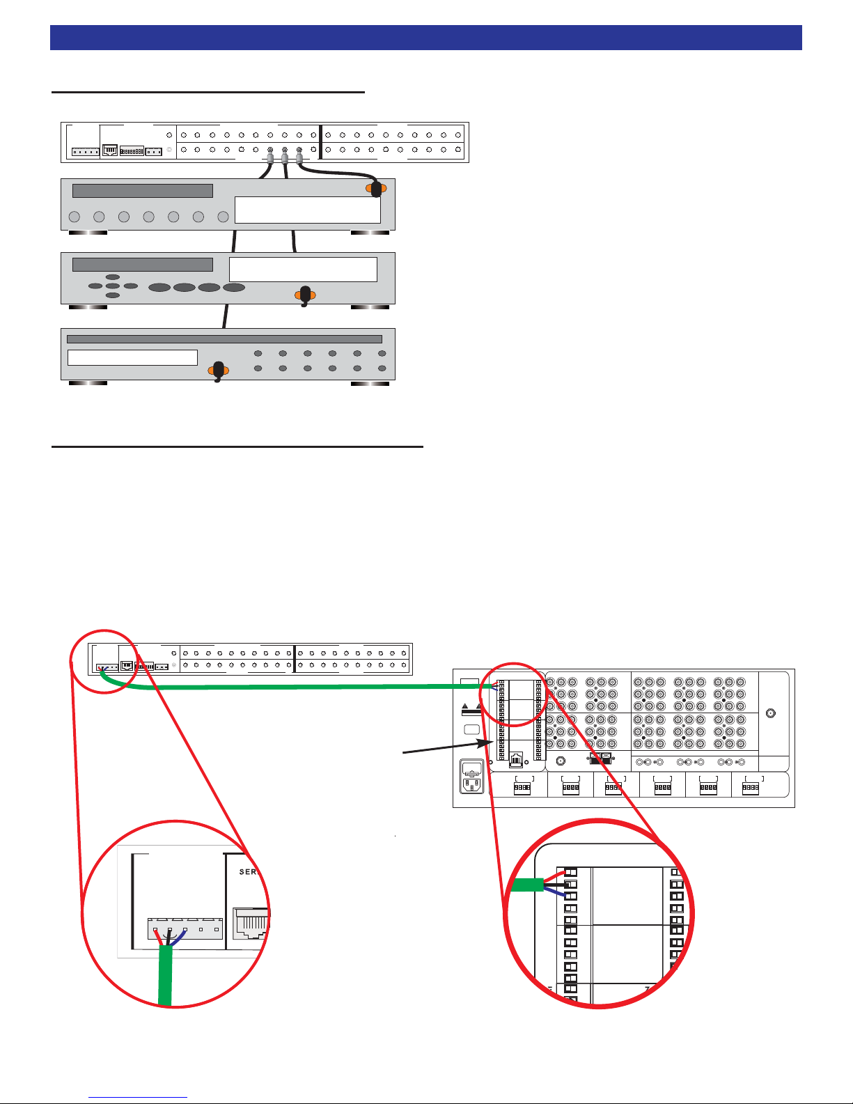
CT-1 Power Connection - 12VDC
Power can be supplied to the CT-1 through any 12VDC (30mA -100mA) power supply. To simplify installation,
utilize the 12VDC power supply from one of the CT610/600 or 310's in the rack. Additionally connect the RS-
232 transmit from the master CT610/600/310 for potential RS-232 communication to a theater receiver or
preamplifier. If RS-232 control is not desired, then the RS-232 portion does not need to be connected.
If RS-232 is not needed, or if all zone keypad ports are being used, then use the 12VDC supply from the
common control +12V and ground.
CT-1 Basic Connection
7
HOME THEATER
FLASHER OUT
CT 3 IR FLASHER IN / [ CHAIN OUT ] CT 2 FLASHER IN
9
CT 1 FLASHER IN
CHAIN
IN
CT IN MASTER
987654321
OUT
87654321
OUT
IN
RS-232
XMIT
ROUTING SENSOR
98765421
[ OUT ]
3
3
OUT 98765421
+12V
GND
RCV
NC
NC
19
+12V
DIN
GND
SERIAL #
ON E
123456789
05 1:23:45
PLAY 8:33
PLAY 8:33
Chan 169
Source 1
Source 2
Source 3
A/V SOURCE INPUTS
CAUTION
RISK OF ELECTRIC SHOCK
DO NOT OPEN
RISK OF ELECTRIC SHOCK
DO NOT OPEN
B&K Components, Ltd.
Made in the U.S.A.
B&K Components, Ltd.
Made in the U.S.A.
www.bkcomp.com
IN
1
IN
1
BUFFERED A/V SOURCE OUTPUTS
ZONE LINE OUTPUTS
VOLTAGE
FM
ANTENNA
FM
ANTENNA
RF REMOTE IN
IN
2
IN
2
IN
3
IN
3
OUT
1
OUT
1
OUT
2
OUT
2
OUT
3
OUT
3
IN
4
IN
4
IN
5
IN
5
IN
6
IN
6
OUT
4
OUT
4
OUT
5
OUT
5
OUT
6
OUT
6
IN
7
IN
7
IN
8
IN
8
IN
9
IN
9
OUT
7
OUT
7
OUT
8
OUT
8
OUT
9
OUT
9
IR 1IR 2
IR 3
IR 4
IR 5
IR 6
IR 7
IR 8
IN
A
IN
A
IN
B
IN
B
IN
C
IN
C
OUT
A
OUT
A
OUT
B
OUT
B
OUT
C
OUT
C
IN
D
IN
D
IN
E
IN
E
IN
F
IN
F
OUT
D
OUT
D
OUT
E
OUT
E
OUT
F
OUT
F
IR 9
AM ANTENNA
AC LINE
~
FUSE
CAUTION: FOR CONTINUED
PROTECTION AGAINST RISK
OF FIRE REPLACE ONLY WITH
SAME TYPE AND VALUE FUSE
CAUTION: FOR CONTINUED
PROTECTION AGAINST RISK
OF FIRE REPLACE ONLY WITH
SAME TYPE AND VALUE FUSE
ZB
ZE +12V
GND
RS232 XMIT
CTRL OUT
DATA IN
ZCZF +12V
GND
RS232 XMIT
CTRL OUT
DATA IN
CONTROL
ZA
ZD +12V
GND
RS232 XMIT
DATA IN
CTRL OUT
RIGHTLEFT
+
-
+
-
ZONE F
RIGHTLEFT
+
-
+
-
ZONE E
RIGHTLEFT
+
-
+
-
ZONE D
RIGHTLEFT
+
-
+
-
ZONE C
RIGHTLEFT
+
-
+
-
ZONE B
RIGHTLEFT
+
-
+
-
ZONE A
SPEAKER OUTPUTS
ARE 4 OHM STABLE
SPEAKER OUTPUTS
ARE 4OHM STABLE
21
RS232
12V
GND
IN
-
IN
-
OUT
IN +
12V
GND
IN
-
IN
-
OUT
IN +
COMMON
CTRL I/O
COMMON
CTRL I/O
OUT
BK&
SBIMPLY ETTER!
HOME THEATER
FLASHER OUT
CT 3 IR FLASHER IN / [ CHAIN OUT ] CT 2 FLASHER IN
9
CT 1 FLASHER IN
CHAIN
IN
CT IN MASTER
987654321
OUT
87654321
OUT
IN
RS-232
XMIT
ROUTING SENSOR
98765421
[ OUT ]
3
3
OUT 98765421
+12V
GND
RCV
NC
NC
19
+12V
DIN
GND
SERIAL #
ON E
123456789
CT IN MASTER
RS-232
XMIT
+12V
GND
RCV
NC
NC
ZB
ZE +12V
GND
RS232 XMIT
CTRL OUT
DATA IN
+12V
GND
CONTROL
ZA
ZD +12V
GND
RS232 XMIT
DATA IN
CTRL OUT
If RS-232 is not needed,
use 12VDC from here

Connecting a Home Theater Product
B&K manufactures Home Theater preamplifier/processors and receiver/processors. Any of these products
can be combined to share sources in a CT system. Depending on which form of control communication you
wish to use (IR or RS-232) B&K can accommodate either or both. Typically only one form of communication
is needed, however for some advanced installations, both forms may be required. The following diagrams
depicts both IR or RS-232 being used to control the home theater product.
The illustrations below will also allow for sources that are only used in the theater zone. Control of those
sources is maintained through the theater keypad or IR sensor. Set the DIP switche(s) to pass IR an un-used
IR flasher output. Otherwise the theater receiver/processor Control Outputs can be set to pass IR.
You may not need both forms of communication connected, only connect what you need.
IR = 1/8” mono mini jack
RS-232 = CAT5 straight through cable
The Home Theater sensor plug (three position phoenix) can be used either for a Keypad (CK1.2) or for an IR
sensor located in the theater room. RS-232 XMIT ports on the CT Receiver back panel are outputs only.
RS-232 Data (BKC-DIP) can be obtained from any zone RS-232 XMIT pin.
B&K RS-232 (BKC-DIP) Information
The CT610/600/310 automatically generates a RS-232 (BKC-DIP) message whenever a B&K IR
command is received. A RS-232 (BKC-DIP) message will not be generated if the IR is not a B & K command.
This RS-232 information is transmitted out the CT Receivers six RS-232 XMIT pins and main RJ-45 jack. In
order to control your home theater piece using RS-232, the IR information must be received through the CT
receiver. Once the IR is received by the CT receiver, a RS-232 (BKC-DIP) message will be generated and
transmitted to control the home theater unit. The theater zone now becomes integrated part of the CT system
via RS-232. The generated RS-232 (BKC-DIP) messages only control functions associated with the home
theater processor. These RS-232 (BKC-DIP) messages will not control non-B&K source pieces.
Connecting a Home Theater Product
8
V1
V2
DVDCDSAT
OPTICAL DIGITAL
OPTICAL DIGITAL
CAUTION
RISKOF ELECTRIC SHOCK
DONOT OPEN
RS-232
12VDC
50mA
+
www.bkcomp.com
Audio/Video Systems Made in the U.S.A.
OUT
V1
ZA OUT V2
TV
DVDZB OUT CDSAT
CONTROL OUT IR IN
ZA
ZB
IEEE
1394
IEEE
1394
ANTENNA
AM FM
1 2
3 4
DVD-AUDIO IN
SUB CENTER
ZA AUDIO OUT
SUB CENTER
FUSE
CAUTION: FOR CONTINUED
PROTECTION AGAINST RISK
OF FIRE REPLACE ONLY WITH
SAME TYPE AND VALUE FUSE
B&K Components, Ltd.
Audio/Video Systems - Made in the U.S.A.
LINE INPUTSLINE OUTPUTSSBACKFRONTSURRFRONTSURR
V1DVDTAPEZB/V2 V2CDTAP EZB TVSATV1ZA IN 1
COMPONENT VIDEO
COMPONENT VIDEO
IN 2 OUT
IN 3
COAX DIGITAL
COAX DIGITAL
BK
&
SBIMPLY ETTER!
OUTPUT
SURROUND BACK LEFTSURROUND LEFT SURROUND RIGHT SURROUND BACK RIGHT FRONT LEFTCENTER FRONT RIGHT
PLUS
+
PLUS
+
PLUS
+
PLUS
+
PLUS
+
PLUS
+
PLUS
+
PLUS
+
PLUS
+
PLUS
+
PLUS
+
PLUS
+
PLUS
+
PLUS
+
MINUS
-
MINUS
-
MINUS
-
MINUS
-
MINUS
-
MINUS
-
MINUS
-
MINUS
-
MINUS
-
MINUS
-
MINUS
-
MINUS
-
MINUS
-
MINUS
-
EXPANSION
AC LINE
SERIAL #
HOME THEATER
FLASHER OUT
CT 3 IR FLASHER IN / [ CHAIN OUT ] CT 2 FLASHER IN
9
CT 1 FLASHER IN
CHAIN
IN
CT IN MASTER
987654321OUT
87654321OUT
IN
RS-232
XMIT
ROUTING SENSOR
987654 21[OUT]3
3OUT 9 8 765421
+12V
GND
RCV
NC
NC
19
+12V
DIN
GND
SERIAL #
1234
ON
56789
A/V SOURCE INPUTS
CAUTION
RISKOF ELECTRIC SHOCK
DONOT OPEN
RISKOF ELECTRIC SHOCK
DONOT OPEN
B&K Components, Ltd.
Made in the U.S.A.
B&K Components, Ltd.
Made in the U.S.A.
www.bkcomp.com
IN
1
IN
1
BUFFERED A/V SOURCE OUTPUTS
ZONE LINE OUTPUTS
VOLTAGE
FM
ANTENNA
FM
ANTENNA
RF REMOTE IN
IN
2
IN
2
IN
3
IN
3
OUT
1
OUT
1
OUT
2
OUT
2
OUT
3
OUT
3
IN
4
IN
4
IN
5
IN
5
IN
6
IN
6
OUT
4
OUT
4
OUT
5
OUT
5
OUT
6
OUT
6
IN
7
IN
7
IN
8
IN
8
IN
9
IN
9
OUT
7
OUT
7
OUT
8
OUT
8
OUT
9
OUT
9
IR 1IR 2
IR 3
IR 4
IR 5
IR 6
IR 7
IR 8
IN
A
IN
A
IN
B
IN
B
IN
C
IN
C
OUT
A
OUT
A
OUT
B
OUT
B
OUT
C
OUT
C
IN
D
IN
D
IN
E
IN
E
IN
F
IN
F
OUT
D
OUT
D
OUT
E
OUT
E
OUT
F
OUT
F
IR 9
AM ANTENNA
AC LINE
~
FUSE
CAUTION: FOR CONTINUED
PROTECTION AGAINST RISK
OF FIRE REPLACE ONLY WITH
SAME TYPE AND VALUE FUSE
CAUTION: FOR CONTINUED
PROTECTION AGAINST RISK
OF FIRE REPLACE ONLY WITH
SAME TYPE AND VALUE FUSE
ZB
ZE +12V
GND
RS232 XMIT
CTRL OUT
DATA IN
ZCZF +12V
GND
RS232 XMIT
CTRL OUT
DATA IN
CONTROL
ZA
ZD +12V
GND
RS232 XMIT
DATA IN
CTRL OUT
RIGHTLEFT
+
-
+
-
ZONE F
RIGHTLEFT
+
-
+
-
ZONE E
RIGHTLEFT
+
-
+
-
ZONE D
RIGHTLEFT
+
-
+
-
ZONE C
RIGHTLEFT
+
-
+
-
ZONE B
RIGHTLEFT
+
-
+
-
ZONE A
SPEAKER OUTPUTS
ARE 4 OHM STABLE
SPEAKER OUTPUTS
ARE 4OHM STABLE
2
1
RS232
12V
GND
IN
-
IN
-
OUT
IN +
12V
GND
IN
-
IN
-
OUT
IN +
COMMON
CTRL I/O
COMMON
CTRL I/O
OUT
BK&
SBIMPLY ETTER!
Attach to
Front Panel
Theater Keypad
or IR Sensor
Connect to
12V & GND
1/8” Mono Mini Jack
IR Connection
V1
V2
DVDCDSAT
OPTICAL DIGITAL
OPTICAL DIGITAL
CAUTION
RISKOF ELECTRIC SHOCK
DONOT OPEN
RS-232
12VDC
50mA
+
www.bkcomp.com
Audio/Video Systems Made in the U.S.A.
OUT
V1
ZA OUT V2
TV
DVDZB OUT CDSAT
CONTROL OUT IR IN
ZA
ZB
IEEE
1394
IEEE
1394
ANTENNA
AM FM
1 2
3 4
DVD-AUDIO IN
SUB CENTER
ZA AUDIO OUT
SUB CENTER
FUSE
CAUTION: FOR CONTINUED
PROTECTION AGAINST RISK
OF FIRE REPLACE ONLY WITH
SAME TYPE AND VALUE FUSE
B&K Components, Ltd.
Audio/Video Systems - Made in the U.S.A.
LINE INPUTSLINE OUTPUTSSBACKFRONTSURRFRONTSURR
V1DVDTAPEZB/V2 V2CDTAP EZB TVSATV1ZA IN 1
COMPONENT VIDEO
COMPONENT VIDEO
IN 2 OUT
IN 3
COAX DIGITAL
COAX DIGITAL
BK
&
SBIMPLY ETTER!
OUTPUT
SURROUND BACK LEFTSURROUND LEFT SURROUND RIGHT SURROUND BACK RIGHT FRONT LEFTCENTER FRONT RIGHT
PLUS
+
PLUS
+
PLUS
+
PLUS
+
PLUS
+
PLUS
+
PLUS
+
PLUS
+
PLUS
+
PLUS
+
PLUS
+
PLUS
+
PLUS
+
PLUS
+
MINUS
-
MINUS
-
MINUS
-
MINUS
-
MINUS
-
MINUS
-
MINUS
-
MINUS
-
MINUS
-
MINUS
-
MINUS
-
MINUS
-
MINUS
-
MINUS
-
EXPANSION
AC LINE
SERIAL #
HOME THEATER
FLASHER OUT
CT 3 FLASHER IN CT 2 FLASHER IN
9
CT 1 FLASHER IN
CHAIN
IN
CT IN MASTER
987654321
CT2
OUT
87654321
CT1
OUT
IN
RS-232
XMIT
ROUTING
RS-232
XMIT SENSOR
98765421
CT3/CHAIN
OUT
3
3
OUT 98765421
+12V
GND
RCV
NC
NC
19
+12V
DIN
GND
SERIAL #
1234
ON
56789
A/V SOURCE INPUTS
CAUTION
RISKOF ELECTRIC SHOCK
DONOT OPEN
RISKOF ELECTRIC SHOCK
DONOT OPEN
B&K Components, Ltd.
Made in the U.S.A.
B&K Components, Ltd.
Made in the U.S.A.
www.bkcomp.com
IN
1
IN
1
BUFFERED A/V SOURCE OUTPUTS
ZONE LINE OUTPUTS
VOLTAGE
FM
ANTENNA
FM
ANTENNA
RF REMOTE IN
IN
2
IN
2
IN
3
IN
3
OUT
1
OUT
1
OUT
2
OUT
2
OUT
3
OUT
3
IN
4
IN
4
IN
5
IN
5
IN
6
IN
6
OUT
4
OUT
4
OUT
5
OUT
5
OUT
6
OUT
6
IN
7
IN
7
IN
8
IN
8
IN
9
IN
9
OUT
7
OUT
7
OUT
8
OUT
8
OUT
9
OUT
9
IR 1IR 2
IR 3
IR 4
IR 5
IR 6
IR 7
IR 8
IN
A
IN
A
IN
B
IN
B
IN
C
IN
C
OUT
A
OUT
A
OUT
B
OUT
B
OUT
C
OUT
C
IN
D
IN
D
IN
E
IN
E
IN
F
IN
F
OUT
D
OUT
D
OUT
E
OUT
E
OUT
F
OUT
F
IR 9
AM ANTENNA
AC LINE
~
FUSE
CAUTION: FOR CONTINUED
PROTECTION AGAINST RISK
OF FIRE REPLACE ONLY WITH
SAME TYPE AND VALUE FUSE
CAUTION: FOR CONTINUED
PROTECTION AGAINST RISK
OF FIRE REPLACE ONLY WITH
SAME TYPE AND VALUE FUSE
ZB
ZE +12V
GND
RS232 XMIT
CTRL OUT
DATA IN
ZCZF +12V
GND
RS232 XMIT
CTRL OUT
DATA IN
CONTROL
ZA
ZD +12V
GND
RS232 XMIT
DATA IN
CTRL OUT
RIGHTLEFT
+
-
+
-
ZONE F
RIGHTLEFT
+
-
+
-
ZONE E
RIGHTLEFT
+
-
+
-
ZONE D
RIGHTLEFT
+
-
+
-
ZONE C
RIGHTLEFT
+
-
+
-
ZONE B
RIGHTLEFT
+
-
+
-
ZONE A
SPEAKER OUTPUTS
ARE 4 OHM STABLE
SPEAKER OUTPUTS
ARE 4OHM STABLE
2
1
RS232
12V
GND
IN
-
IN
-
OUT
IN +
12V
GND
IN
-
IN
-
OUT
IN +
COMMON
CTRL I/O
COMMON
CTRL I/O
OUT
BK
&
SBIMPLY ETTER!
Connect to
12V, GND & RS232
Straight through
CAT5 Cable
Attach to
Front Panel
CT-1 CT-1
Home Theater
Receiver RS-232 Connection

Non-Identical Shared Sources with a Theater
The following diagram illustrates a CT600 and an AVR507 sharing a DVD player. Only one source is
illustrated here for simplicity. Use the diagram below to add additional non-identical sources. In this diagram,
RS-232 (CAT5) is being used to integrate the AVR507 into the CT system. If IR communication is desired
instead of RS-232, refer to the previous page for the IR Connection diagram. RS-232 is illustrated here
because it has a less susceptible to outside interference (i.e. plasma, florescent light, etc.). All nine IR
Flashers should be connected from the CT Receiver to the CT-1. Emitters are connected from the Flasher
output(s) to the front panel of the source device(s). Any component video and digital audio signals should be
connected directly to the AVR507 since the CT does not process either type of signal. The buffered outputs
on the CT Receiver pass the analog audio and composite video signals to the AVR507. Also, a CK1.2
Keypad can be used in place of an IR sensor in the home theater room if use of a remote controller is
desired. This example provides full control over both the Main Home Theater zone and the sources used in
the Theater zone.
Using this system example, if a source is not intended to be "shared" with the rest of the house, control of
that source from the keypad is accomplished by simply connecting an emitter from an un-used FLASHER
OUT on the CT-1 to that source. Set the dip switch accordingly, see section below.
DIP Switch Routing
In the diagram above, the DVD is located on INPUT 2 of the CT Receiver. DIP
switch number 2 needs to be switched ON (up) in order for the IR signal to pass from
the theater keypad or IR sensor to the DVD player. Whenever a DIP switch is set to
ON, it is merely allowing IR to pass from either of the Home Theater IR inputs to the
selected Flasher Outputs. Identical sources cannot be shared between a home
theater and a CT Receiver using this connection method.
Connecting a Home Theater Product
V1
V2
DVDCDSAT
OPTICAL DIGITALOPTICAL DIGITAL
CAUTION
RISK OF ELECTRIC SHOCK
DO NOT OPEN
RS-232
12VDC
50mA
+
www.bkcomp.com
Audio/Video Systems Made in the U.S.A.
OUT
V1
ZA OUT V2
TV
DVDZB OUT CDSAT
CONTROL OUT IR IN
ZA
ZB
IEEE
1394
IEEE
1394
ANTENNA
AM FM
1 2
3 4
DVD-AUDIO IN
SUB CENTER
ZA AUDIO OUT
SUB CENTER
FUSE
CAUTION: FOR CONTINUED
PROTECTION AGAINST RISK
OF FIRE REPLACE ONLY WITH
SAME TYPE AND VALUE FUSE
B&K Components, Ltd.
Audio/Video Systems - Made in the U.S.A.
LINE INPUTSLINE OUTPUTSS BACKFRONTSURRFRONTSURR
V1DVDTAP EZB/V2 V2CDTAP EZB TVSATV1ZA IN 1
COMPONENT VIDEOCOMPONENT VIDEO
IN 2 OUT
IN 3
COAX DIGITALCOAX DIGITAL
BK
&
SBIMPLY ETTER!
OUTPUT
SURROUND BACK LEFTSURROUND LEFT SURROUND RIGHT SURROUND BACK RIGHT FRONT LEFTCENTER FRONT RIGHT
PLUS
+
PLUS
+
PLUS
+
PLUS
+
PLUS
+
PLUS
+
PLUS
+
PLUS
+
PLUS
+
PLUS
+
PLUS
+
PLUS
+
PLUS
+
PLUS
+
MINUS
-
MINUS
-
MINUS
-
MINUS
-
MINUS
-
MINUS
-
MINUS
-
MINUS
-
MINUS
-
MINUS
-
MINUS
-
MINUS
-
MINUS
-
MINUS
-
EXPANSION
AC LINE
SERIAL #
HOME THEATER
FLASHER OUT
CT 3 IR FLASHER IN / [ CHAIN OUT ] CT 2 FLASHER IN
9
CT 1 FLASHER IN
CHAIN
IN
CT IN MASTER
987654321
OUT
87654321
OUT
IN
RS-232
XMIT
ROUTING SENSOR
98765421
[ OUT ]
3
3
OUT 98765421
+12V
GND
RCV
NC
NC
19
+12V
DIN
GND
SERIAL #
1234
ON
56789
B&K AVR507
B&K CT600
DVD Player (IN2)
Theater
CK1.2 or IR Sensor
A/V SOURCE INPUTS
CAUTION
RISK OF ELECTRIC SHOCK
DO NOT OPEN
RISK OF ELECTRIC SHOCK
DO NOT OPEN
B&K Components, Ltd.
Made in the U.S.A.
B&K Components, Ltd.
Made in the U.S.A.
www.bkcomp.com
IN
1
IN
1
BUFFERED A/V SOURCE OUTPUTS
ZONE LINE OUTPUTS
VOLTAGE
FM
ANTENNA
FM
ANTENNA
RF REMOTE IN
IN
2
IN
2
IN
3
IN
3
OUT
1
OUT
1
OUT
2
OUT
2
OUT
3
OUT
3
IN
4
IN
4
IN
5
IN
5
IN
6
IN
6
OUT
4
OUT
4
OUT
5
OUT
5
OUT
6
OUT
6
IN
7
IN
7
IN
8
IN
8
IN
9
IN
9
OUT
7
OUT
7
OUT
8
OUT
8
OUT
9
OUT
9
IR 1IR 2
IR 3
IR 4
IR 5
IR 6
IR 7
IR 8
IN
A
IN
A
IN
B
IN
B
IN
C
IN
C
OUT
A
OUT
A
OUT
B
OUT
B
OUT
C
OUT
C
IN
D
IN
D
IN
E
IN
E
IN
F
IN
F
OUT
D
OUT
D
OUT
E
OUT
E
OUT
F
OUT
F
IR 9
AM ANTENNA
AC LINE
~
FUSE
CAUTION: FOR CONTINUED
PROTECTION AGAINST RISK
OF FIRE REPLACE ONLY WITH
SAME TYPE AND VALUE FUSE
CAUTION: FOR CONTINUED
PROTECTION AGAINST RISK
OF FIRE REPLACE ONLY WITH
SAME TYPE AND VALUE FUSE
ZB
ZE +12V
GND
RS232 XMIT
CTRL OUT
DATA IN
ZCZF +12V
GND
RS232 XMIT
CTRL OUT
DATA IN
CONTROL
ZA
ZD +12V
GND
RS232 XMIT
DATA IN
CTRL OUT
RIGHTLEFT
+
-
+
-
ZONE F
RIGHTLEFT
+
-
+
-
ZONE E
RIGHTLEFT
+
-
+
-
ZONE D
RIGHTLEFT
+
-
+
-
ZONE C
RIGHTLEFT
+
-
+
-
ZONE B
RIGHTLEFT
+
-
+
-
ZONE A
SPEAKER OUTPUTS
ARE 4 OHM STABLE
SPEAKER OUTPUTS
ARE 4OHM STABLE
2 1
RS232
12V
GND
IN
-
IN
-
OUT
IN +
12V
GND
IN
-
IN
-
OUT
IN +
COMMON
CTRL I/O
COMMON
CTRL I/O
OUT
BK&BK&
SBIMPLY ETTER!SBIMPLY ETTER!
PLAY 8:33
Connect directly
to the AVR507
Attach to
Front
Panel
*
ROUTING
19
1234
ON
56789
9
Analog Left, Right & Composite
Digital
Component
Straight through CAT5 RS-232 Data Line

Chaining Multiple CT-1’s
Multiple CT-1 IR Integrators can be combined for very large systems. A total of 11 CT-1’s can be chained
together to form 126 independent stereo zones. This allows IR control of the entire CT system and each of
the nine shared source devices. Each additional CT-1 uses one of the three CT FLASHER IN sections on the
CT-1. Each multi-linked CT-1 will accommodate a maximum of two CT receivers (See diagram below). Using
this method will allow IR routing from any of
the 126 potential independent zones to any
of the nine shared sources. The diagram
shown to the right illustrates six CT
receivers linked together (36 stereo zones).
Always connect all 9 IR flashers from the
CT receiver(s) to the CT-1. This is needed
for proper IR routing when the dedicated
inputs or the tuner is selected.
Notice that IR is passed between CT-1s
using the CHAIN OUT to CHAIN IN 1/8” mini
jacks. Therefore, IR data passes from CT-1
#1 to CT-1 #2 to CT-1 #3. Additional CT-1s
can be added at the bottom of this chain by
continuing the method shown. Source
devices are always connected to the last
CT-1 in the chain. A maximum of 11 CT-1s
can be chained together.
IR data cannot be passed “up” the chain of CT-1s (from #3 to #1). Keypads that are programmed with whole
house control (code 000), need to be connected to CT Receiver #1 or #2 in this example. Keypads that
intended to control other zones in the house will only have the ability to control zones located downstream of
where that keypad’s IR signal is entering the chain.
Please refer to our website for additional information pertaining to specific installation scenarios and
programming the system keypads.
www.bkcomp.com
Multiple CT-1 Chaining
HOME THEATER
FLASHER OUT
CT 3 IR FLASHER IN / [ CHAIN OUT ] CT 2 FLASHER IN
9
CT 1 FLASHER IN
CHAIN
IN
CT IN MASTER
987654321
OUT
87654321
OUT
IN
RS-232
XMIT
ROUTING SENSOR
98765421
[OUT]
3
3
OUT 98765421
+12V
GND
RCV
NC
NC
19
+12V
DIN
GND
SERIAL #
ON E
123456789
HOME THEATER
FLASHER OUT
CT 3 IR FLASHER IN / [ CHAIN OUT ] CT 2 FLASHER IN
9
CT 1 FLASHER IN
CHAIN
IN
CT IN MASTER
987654321
OUT
87654321
OUT
IN
RS-232
XMIT
ROUTING SENSOR
98765421
[ OUT ]
3
3
OUT 98765421
+12V
GND
RCV
NC
NC
19
+12V
DIN
GND
SERIAL #
ON E
123456789
HOME THEATER
FLASHER OUT
CT 3 IR FLASHER IN / [ CHAIN OUT ] CT 2 FLASHER IN
9
CT 1 FLASHER IN
CHAIN
IN
CT IN MASTER
987654321
OUT
87654321
OUT
IN
RS-232
XMIT
ROUTING SENSOR
98765421
[ OUT ]
3
3
OUT 98765421
+12V
GND
RCV
NC
NC
19
+12V
DIN
GND
SERIAL #
ON E
123456789
05 1:23:45
PLAY 8:33
PLAY 8:33
Chan 169
#1 CT Rcvr #1
CT Rcvr #2
CT Rcvr #3
CT Rcvr #4
CT Rcvr #5
CT Rcvr #6
#2
#3
CT-1 Daisy Chain Example
Table of contents
Other B&K Recording Equipment manuals


Popular Recording Equipment manuals by other brands


Masoneilan
Masoneilan SVI II ESD Installation and maintenance manual

Abatron
Abatron BDI2000 user manual

Extron electronics
Extron electronics CIA111 user manual

Apollo
Apollo REACH WIRELESS RW1700-030APO quick start guide

Joemeek
Joemeek MicroMeek MQ3 user guide

Belden
Belden GRASS VALLEY DENSITE Series Guide to installation and operation