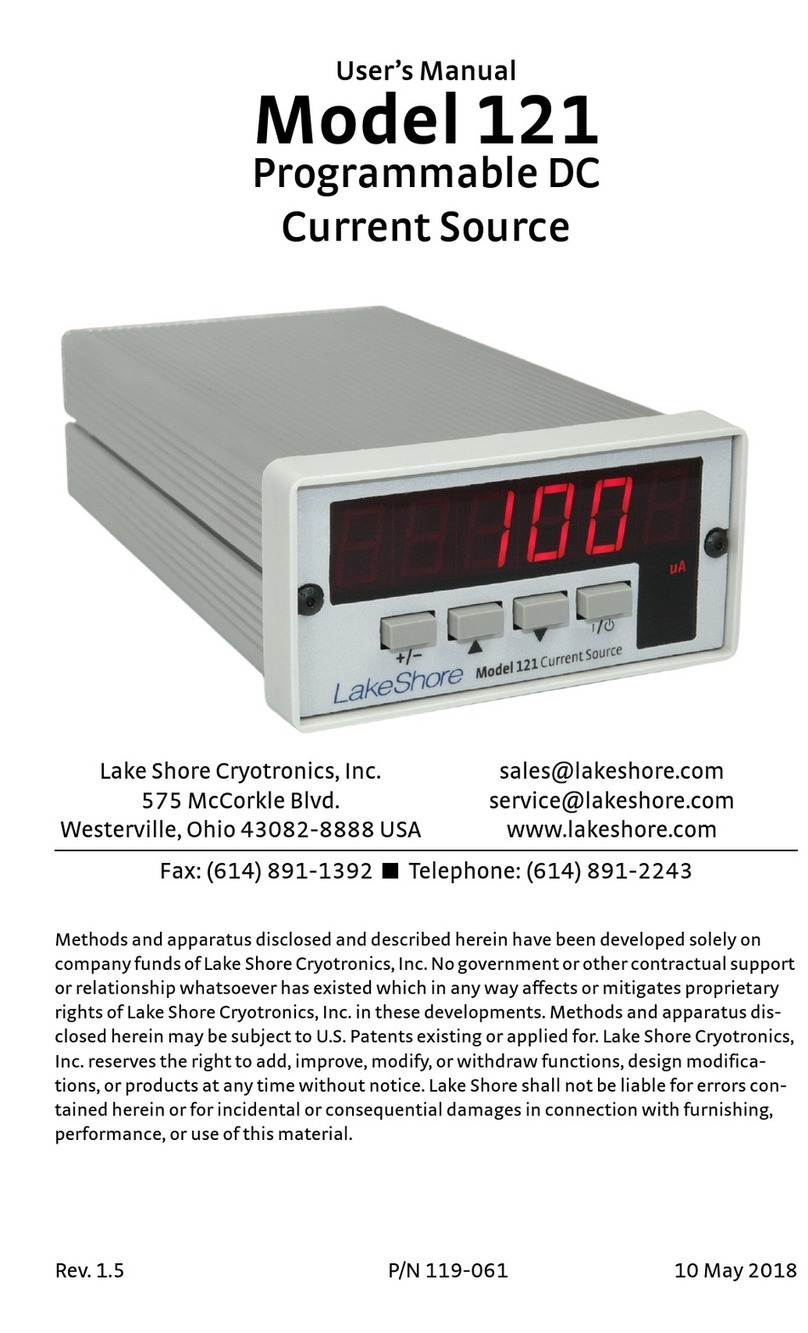
Lake Shore Cryotronics 1015 User manual

Revision 1.1 P/N 119-010 5 November 1999
USER’S MANUAL
Model 1015
Warm-Up Power Supply
Lake Shore Cryotronics, Inc.
575 McCorkle Boulevard
Westerville, Ohio 43082-8888 USA
E-Mail Addresses:
Visit Our Website:
www.lakeshore.com
Fax: (614) 891-1392
Telephone: (614) 891-2243
Methods and apparatus disclosed and described herein have been developed solely on company funds of Lake
Shore Cryotronics, Inc. No government or other contractual support or relationship whatsoever has existed which
in any way affects or mitigates proprietary rights of Lake Shore Cryotronics, Inc. in these developments. Methods
and apparatus disclosed herein may be subject to U.S. Patents existing or applied for. Lake Shore Cryotronics,
Inc. reserves the right to add, improve, modify, or withdraw functions, design modifications, or products at any time
without notice. Lake Shore shall not be liable for errors contained herein or for incidental or consequential
damages in connection with furnishing, performance, or use of this material

Lake Shore Model 1015 User’s Manual
A
LIMITED WARRANTY
Lake Shore Cryotronics, Inc. (henceforth Lake Shore), the manufacturer, warrants this
product for a period of 12 months from the date of shipment. During the warranty
period, under authorized return of instruments or component parts to Lake Shore
freight prepaid, the company will repair, or at its option replace, any part found to be
defective in material or workmanship, without charge to the Owner for parts, service
labor or associated customary shipping cost. Replacement or repaired parts will be
warranted for only the unexpired portion of the original warranty.
All products are thoroughly tested and calibrated to published specifications prior to
shipment. Calibration Certifications are offered for 6 month periods only. Where such
documentation must be updated, a re-certification service is offered by Lake Shore at
a reasonable cost.
LIMITATION OF WARRANTY
This warranty is limited to Lake Shore products purchased and installed in the United
States. This same protection will extend to any subsequent owner during the
warranty period. It does not apply to damage caused by accident, misuse, fire, flood,
or acts of God, from failure to properly install, operate, or maintain the product in
accordance with the printed instructions provided. This warranty does not apply to
defects resulting from improper or inadequate maintenance, unauthorized
modification or misuse, operation outside of the environmental specifications for any
product or part or buyer-supplied software interfacing.
THIS WARRANTY IS IN LIEU OF ANY OTHER WARRANTIES, EXPRESSED OR
IMPLIED, INCLUDING MERCHANTABILITY OR FITNESS FOR A PARTICULAR
PURPOSE, WHICH ARE EXPRESSLY EXCLUDED. THE OWNER AGREES THAT
LAKE SHORE’S LIABILITY WITH RESPECT TO THIS PRODUCT SHALL BE SET
FORTH IN THIS WARRANTY, AND INCIDENTAL OR CONSEQUENTIAL
DAMAGES ARE EXPRESSLY EXCLUDED.
CERTIFICATION
Lake Shore certifies that this product has been inspected and tested in accordance
with its published specifications and that this product met its published specifications
at the time of shipment. The accuracy and calibration of this product at the time of
shipment are traceable to the United States National Institute of Standards and
Technology (NIST); formerly known as the National Bureau of Standards (NBS), or to
a recognized natural standard.
TRADEMARK ACKNOWLEDGEMENT
Manufacturers and sellers claim many designations as trademarks to distinguish their
products. Where those designations appear in this manual and Lake Shore was
aware of a trademark claim, the designations appear in initial capital letters with a
™ or ®symbol.
Apiezon®is a trademark of Biddle Instruments.
Cryo-Gloves®is a trademark of Tempshield.
Duo-Twist™, Quad-Lead™, Quad-Twist™, and SoftCal™ are trademarks of
Lake Shore Cryotronics, Inc.
Teflon®is a trademark of DuPont De Nemours.
Copyright © 1988, 1997, and 1999 by Lake Shore Cryotronics, Inc. All rights reserved.
No portion of this manual may be reproduced, stored in a retrieval system, or
transmitted, in any form or by any means, electronic, mechanical, photocopying,
recording, or otherwise, without the express written permission of Lake Shore.

Lake Shore Model 1015 User’s Manual
Table of Contents i
TABLE OF CONTENTS
Chapter/Paragraph Title Page
1 INTRODUCTION..............................................................................1-1
1.0 General ..........................................................................1-1
1.1 Model 1015 System Description ....................................1-1
1.2 Electrostatic Discharge ..................................................1-2
1.2.1 Identifying ESDS Components ...................................1-3
1.2.2 Handling ESDS Components .....................................1-3
1.3 Safety Summary.............................................................1-3
1.4 Safety Symbols ..............................................................1-4
2 INSTALLATION...............................................................................2-1
2.0 General ..........................................................................2-1
2.1 Inspection and Unpacking..............................................2-1
2.2 Repackaging For Shipment............................................2-1
2.3 Power and Ground Requirements..................................2-2
2.4 Bench Use......................................................................2-2
2.5 Rack Mounting ...............................................................2-3
2.6 Sensor Input Connections..............................................2-3
2.7 Environmental Requirements.........................................2-3
3 OPERATION....................................................................................3-1
3.1 Controls and Indicators ..................................................3-1
3.2 Operation .......................................................................3-3
3.2.1 HI/LO Power Selection ...............................................3-3
3.2.2 Power ON/OFF ...........................................................3-3
3.2.3 SINGLE Cycle Operation............................................3-3
3.2.4 CONTINUOUS Cycle Operation.................................3-4
4 MAINTENANCE...............................................................................4-1
4.1 Fuse Replacement.........................................................4-1
4.2 Line Voltage Configuration.............................................4-1
4.3 Calibration and Troubleshooting ....................................4-1
A GLOSSARY OF TERMINOLOGY .................................................. A-1
B HANDLING OF LIQUID HELIUM AND NITROGEN....................... B-1

Lake Shore Model 1015 User’s Manual
ii Table of Contents
LIST OF ILLUSTRATIONS
Figure No. Title Page
2-1 Typical Rack Configuration ...................................................... 2-3
2-2 Sensor Connections................................................................. 2-4
3-1 Model 1015 Front Panel........................................................... 3-1
3-2 Model 1015 Rear Panel ........................................................... 3-2
LIST OF TABLES
Table No. Title Page
1-1 Model 1015 Specifications....................................................... 1-2
2-1 Line Voltage Selection ............................................................. 2-2
2-1 Sensor Connections for the J1 and J2 Inputs.......................... 2-3
B-1 Comparison of Liquid Helium to Liquid Nitrogen...................... B-1

Lake Shore Model 1015 User’s Manual
Introduction 1-1
CHAPTER 1
INTRODUCTION
1.0 GENERAL
The Model 1015 was designed and manufactured in the United
States of America by Lake Shore Cryotronics, Inc. This chapter
provides a general description in Paragraph 1.1, Electrostatic
Discharge in Paragraph 1.2, safety summary in Paragraph 1.3, and
safety symbols in Paragraph 1.4.
1.1 MODEL 1015 GENERAL DESCRIPTION
The Model 1015 is designed specifically for use with Series 100
Cryogenic Test Stations. It provides up to 80 watts of heater power
on each of two channels to warm both the first and second stage of
the test station to room temperature for rapid sample turn around.
The Model 1015 contains two temperature monitoring circuits to
control each heater channel. The Model 1015 monitors the
temperature of each stage via the diode temperature sensors
mounted on each, and automatically shuts down when each of the
stages reaches room temperature.
There are two different power levels available for each channel to
accommodate different test set-ups or heating requirements; a low
range (LO) of 25 watts and a high range (HI) of 80 watts into a 25 !
load.
Front panel controls and indicators allow users to select power levels
and monitor unit status. Monitor power applied to the heaters
(POWER ON HI or POWER ON LO), stage status (READY or WAIT),
as well as operational status (START or STOP) from the front panel.
The rear panel contains the sensor input and heater output for each
stage as well as the selection of continuous or one-shot operation
and cycle timing.

Lake Shore Model 1015 User’s Manual
1-2 Introduction
Table 1-1. Model 1015 Specifications
Sensor Inputs: Dual two-lead silicon diode inputs through 5-pin
socket connectors, with sensor open and short circuit heater
power shut-off protection, and heater open circuit shut-off
protection.
Sensor Excitation: Nominal 10 µA constant current.
Configuration DIP Switches: Bank of four DIP switches selects
SINGLE or CONTINUOUS cycle; and 10, 5, and 1 minute
cycle delay times (timeouts).
HEATER HI and LO Outputs: Binding posts for HEATER HI (+)
and LO (-) outputs for each stage.
Output Power: LO – Up to 25 W (1 A, 25 V) into a 25 !load.
HI – Up to 80 W (1.75 A, 45 V) into a 25 !load.
Operating Temperature: 15-35 °C
Dimensions: 21.6 ×10.2 ×33 cm (8.5 ×4×15 inches)
Style L, half-rack
Net Weight: 7 kilograms (15.4 pounds)
Power: Rear panel selectable 110/120/220/240 VAC, +5% –10%;
50-60 Hz; 350 VA.
NOTE: Product Specifications subject to change without notice.
1.2 ELECTROSTATIC DISCHARGE
Electrostatic Discharge (ESD) is a transfer of electrostatic charge
between bodies at different electrostatic potentials caused by direct
contact or induced by an electrostatic field. It may damage electronic
parts, assemblies, and equipment. The low-energy source that most
commonly destroys Electrostatic Discharge Sensitive (ESDS) devices is
the human body, which generates and retains static electricity. Simply
walking across a carpet in low humidity may generate up to 35,000
volts of static electricity.
Current technology trends toward greater complexity, increased
packaging density, and thinner dielectrics between active elements,
which results in electronic devices with even more ESD sensitivity.
Some electronic parts are more ESDS than others. ESD levels of
only a few hundred volts may damage electronic components such
as semiconductors, thick and thin film resistors, and piezoelectric
crystals during testing, handling, repair, or assembly. Discharge
voltages below 4000 volts cannot be seen, felt, or heard.

Lake Shore Model 1015 User’s Manual
Introduction 1-3
1.2.1 Identifying ESDS Components
Below are industry symbols used to label ESDS components:
1.2.2 Handling ESDS Components
Observe all precautions to prevent damage to ESDS components
before installation. Bring the device and everything that contacts it
to ground potential by providing a conductive surface and
discharge paths. At a minimum, observe these precautions:
1. De-energize or disconnect all power and signal sources and
loads used with unit.
2. Place unit on a grounded conductive work surface.
3. Ground technician through a conductive wrist strap (or other
device) using 1 M!series resistor to protect operator.
4. Ground any tools, such as soldering equipment, that contact
unit. Contact with operator's hands provides a sufficient
ground for tools that are otherwise electrically isolated.
5. Place ESDS devices and assemblies removed from a unit on a
conductive work surface or in a conductive container. An
operator inserting or removing a device or assembly from a
container must maintain contact with a conductive portion of
the container. Use only plastic bags approved for storage of
ESD material.
6. Do not handle ESDS devices unnecessarily or remove from
the packages until actually used or tested.
1.3 SAFETY SUMMARY
Observe these general safety precautions during all phases of
instrument operation, service, and repair. Failure to comply with
these precautions or with specific warnings elsewhere in this manual
violates safety standards of design, manufacture, and intended
instrument use. Lake Shore Cryotronics, Inc. assumes no liability for
Customer failure to comply with these requirements.
Ground The Instrument
To minimize shock hazard, connect instrument chassis and cabinet
to an electrical ground. The instrument comes with a 3-conductor
AC power cable. Plug it into an approved three-contact electrical
outlet or use a three-contact adapter with the green ground wire
firmly secured to an electrical ground (safety ground) at the power
outlet. The power cable jack and mating plug meet Underwriters
Laboratories (UL) and International Electrotechnical Commission
(IEC) safety standards.

Lake Shore Model 1015 User’s Manual
1-4 Introduction
Do Not Operate In An Explosive Atmosphere
Do not operate the instrument in the presence of flammable gases
or fumes. Operation of any electrical instrument in such an
environment constitutes a definite safety hazard.
Keep Away From Live Circuits
Operating personnel must not remove instrument covers. Refer
component replacement and internal adjustments to qualified
maintenance personnel. Do not replace components with power
cable connected. To avoid injuries, always disconnect power and
discharge circuits before touching them.
Do Not Substitute Parts Or Modify Instrument
Do not install substitute parts or perform any unauthorized
modification to the instrument. Return the instrument to an
authorized Lake Shore Cryotronics, Inc. representative for service
and repair to ensure that safety features are maintained.
1.4 SAFETY SYMBOLS
Direct current (power line).
Alternating current (power line).
Alternating or direct current (power line).
Three-phase alternating current (power line).
Earth (ground) terminal.
Protective conductor terminal.
Frame or chassis terminal.
On (supply)
Off (supply)
Equipment protected throughout by double insulation or reinforced
insulation (equivalent to Class II of IEC 536, Annex H).
Caution: High voltages or temperatures. Background color: Yellow;
Symbol and outline: Black.
Caution or Warning - See instrument documentation. Background
color: Yellow; Symbol and outline: Black.
Y

Lake Shore Model 1015 User’s Manual
Installation 2-1
CHAPTER 2
INSTALLATION
2.0 GENERAL
This chapter details inspection and unpacking in Paragraph 2.1,
repackaging for shipment in Paragraph 2.2, sensor installation in
Paragraph 2.3, power and ground requirements in Paragraph 2.4, load
connection in Paragraph 2.5, sensor installation recommendations in
Paragraph 2.6, and rack mounting in Paragraph 2.7.
2.1 INSPECTION AND UNPACKING
Inspect shipping containers for external damage. Make all claims for
damage (apparent or concealed) or partial loss of shipment in writing
to Lake Shore within 5 days from receipt of goods. If damage or loss
is apparent, please notify the shipping agent immediately.
Open the shipping containers. Use the packing list included with the
system to verify receipt of the instrument, sensor, accessories, and
manual. Inspect for damage. Inventory all components supplied
before discarding any shipping materials. If there is freight damage to
the instrument, file proper claims promptly with the carrier and
insurance company and notify Lake Shore. Notify Lake Shore
immediately of any missing parts. Lake Shore cannot be responsible
for any missing parts unless notified within 60 days of shipment.
2.2 REPACKAGING FOR SHIPMENT
To return the Model 1015 or accessories for repair or replacement,
obtain a Return Goods Authorization (RGA) number from Technical
Service in the United States, or from the authorized sales/service
representative from which the product was purchased. Instruments
may not be accepted without a RGA number. When returning an
instrument for service, Lake Shore must have the following
information before attempting any repair.
1. Instrument model and serial number.
2. User name, company, address, and phone number.
3. Malfunction symptoms.
4. Description of system.
5. Returned Goods Authorization (RGA) number.
Repack the system in its original container (if available). Affix
shipping labels and FRAGILE warnings. Write RGA number on the
outside of the container or on the packing slip. If not available,
consult Lake Shore for shipping and packing instructions.

Lake Shore Model 1015 User’s Manual
2-2 Installation
2.3 POWER AND GROUND REQUIREMENTS
The Model 1015 requires a power source of 100, 120, 220 or 240
VAC (+5%, –10%), 50 to 60 Hz single phase. The instrument
includes a three-prong detachable power cord for 120 VAC operation
which mates with the rear panel UL/IEC/ICEE Standard plug.
CAUTION: Verify that the rear panel AC Line Voltage Selection
Wheel (Figure 3-2, Key 1) is set to the AC voltage source
to be used (Table 2-1) and that the proper fuse is
installed before inserting the power cord and turning on
the instrument.
To protect operating personnel, the National Electrical Manufacturer's
Association (NEMA) recommends, and some local codes require,
instrument panels and cabinets be gounded. This instrument is
equipped with a three-conductor power cable which, when plugged
into an appropriate receptacle, grounds the instrument.
Table 2-1. Line Voltage Selection
Line Voltage
(Volts)
Operating
Range (Volts)
Slow Blow
Fuse (Amps)
100 90 –105 5.0
120 108 –126 5.0
220 198 –231 2.5
240 216 –252 2.5
2.4 BENCH USE
The Model 1015 ships with feet and a tilt stand installed and is ready
to use as a bench instrument. Extend the tilt stand to elevate the front
of the instrument for operating and viewing convenience. Do not
subject the Model 1015 to excessive shock and vibrations like those
that usually accompany high vacuum pumping systems.

Lake Shore Model 1015 User’s Manual
Installation 2-3
2.5 RACK MOUNTING
Purchase a PM-3H1 or PM-3H2 rack mounting kit to install the Model
1015 in a standard 19-inch instrument rack.
P-1015-2-1.bmp
Figure 2-1. Typical Rack Configuration
2.6 SENSOR INPUT CONNECTIONS
The sensor input connectors J1 and J2 on the Model 1015 rear panel
provide connections for the First and Second Stage inputs. The
connector definitions are listed in Table 2-2.
Use a four-wire connection (Figure 2-1A) to avoid introducing IR
drops in the voltage sensing pair which causes temperature
measurement error. Use the alternate two-wire connection (Figure 2-
1B) in less critical applications where lead resistance is small and
small readout errors can be tolerated.
Lake Shore 36-Gauge Cryogenic wire is ideal for sensor connections.
The four Phosphor Bronze leads with Formvar insulation are bonded
together and color-coded red, green, clear and blue for easy wire
identification.
2.7 ENVIRONMENTAL REQUIREMENTS
WARNING: To prevent electrical fire or shock hazards, do not
expose this instrument to rain or excess moisture.
To meet and maintain specifications in Table 1-1, operate the Model
1015 at an ambient temperature range of 23 ±5 °C. Operate within
the range of 15 –35 °C with reduced accuracy.
The Model 1015 is for laboratory use. No humidity or altitude
specifications have been determined for this unit.

Lake Shore Model 1015 User’s Manual
2-4 Installation
Table 2-2. Sensor Connections for the J1 and J2 Inputs
Terminal Description
A + Current Out
B – Current Out
D – Voltage Sense
E + Voltage Sense
SENSOR
A (+I)
E (+V)
D (-V)
B (-I)
C: Two-Lead Sensor
Two-Lead Hookup
SENSOR
A (+I)
E (+V)
D (-V)
B (-I)
B: Two-Lead Sensor
Four-Lead Hookup
SENSOR
A (+I)
E (+V)
D (-V)
B (-I)
A: Four-Lead Sensor
Four-Lead Hookup
F-1015-2-2.eps
Figure 2-2. Sensor Connections

Lake Shore Model 1015 User’s Manual
Operation 3-1
CHAPTER 3
OPERATION
3.1 CONTROLS AND INDICATORS
Figures 3-1 and 3-2 identify the various Model 1015 front and rear
panel annunciators, controls, and connectors.
START
POWER
13 4
READY
WAIT
POWER
ON HI
ON LO
FIRST STA E
READY
WAIT
POWER
ON HI
ON LO
SECOND STA E
STOP
2
1015 WARM-UP POWER SUPPLY
F-1015-3-1.eps
!First Stage Block – Annunciated POWER, READY, and WAIT
indicators and power setting selection for the First Stage.
"Second Stage Block – Annunciated POWER, READY, and WAIT
indicators and power setting selection for the Second Stage.
#START/STOP – Annunciated START/STOP warm-up cycle
operation.
$Power ON/OFF Switch.
Figure 3-1. Model 1015 Front Panel

Lake Shore Model 1015 User’s Manual
3-2 Operation
HI
10 min
5 mincont
H
BA
DE
120Vac
LO
FIRST STA E
HI
H
BA
DE
LO
SECOND STA E
21 34 5
6
F-1015-3-2.eps
!AC Receptacle – AC power input, line voltage selection, and
fuse.
"J1 – Input connector for the First Stage sensor.
#J2 – Input connector for the Second Stage sensor.
$J3 and J4 – Heater Output for the First Stage.
%J5 and J6 – Heater Output for the Second Stage.
&Configuration Switch – DIP switch selection of SINGLE or
CONTINUOUS cycle operation; 10, 5, and 1 minute cycle delay
times (timeouts).
Figure 3-2. Model 1015 Rear Panel

Lake Shore Model 1015 User’s Manual
Operation 3-3
3.2 OPERATION
3.2.1 HI / LO Power Selection
Prior to turning on the unit, select the HI (80 watt) or LO (25 watt)
power setting for each stage.
3.2.2 Power ON/OFF
Before connecting AC power to the Model 1015, verify rear panel
line voltage selector corresponds to the available power line
voltage. Verify correct fuse installation.
Immediately after power ON, the Model 1015 enters the STOP
condition: STOP annunciator on, all others off. In the STOP
condition, the unit applies no power to the heaters.
3.2.3 SINGLE Cycle Operation
In SINGLE cycle operation, the Model 1015 warms the first and
second stages to room temperature. Upon reaching room
temperature, the Model 1015 shuts off heater output to that stage
and does not allow it to go back on.
To select the SINGLE cycle operation, switch the rear panel CONT
switch to the down position. To initiate the warm-up cycle, press
the front panel START button. The START LED lights and the unit
monitors the First and Second stage sensor inputs to determine if
they are already at room temperature. If they are, the stage enters
the READY state. If not, the unit turns on the power to the stage
and indicates it by lighting the red POWER LED.
If the POWER LED does not light and the stage is not READY,
there is a fault in either the sensor or heater connections. The unit
applies power to the stages until they are both at room
temperature, or READY. Terminate the warm-up cycle at any point
by pressing the STOP button. The STOP button returns the unit to
the power-up state.

Lake Shore Model 1015 User’s Manual
3-4 Operation
3.2.4 CONTINUOUS Cycle Operation
In CONTINUOUS (CONT) mode, the Model 1015 continues to
apply heater power to a stage until the stage remains at room
temperature for the cycle delay time (timeout).
To select the CONT mode, switch the rear panel CONT switch to
the up position and select a timeout. To select a 10 minute timeout
place the 10 min switch in the up position, and the 5 min switch in
the down position. To select a 5 minute timeout, place the 5 min
switch in the up position, and the 10 min switch in the down
position. To select a 1 minute timeout put both the 10 min and
5 min switches in the down position (both the 10 min and 5 min
switches in the up position selects a 10 minute timeout).
To initiate the warm-up cycle, press the front panel START button.
The START LED lights and the unit monitors the First and Second
stage temperatures to determine if they are at room temperature. If
they are, the yellow WAIT LED lights and the unit monitors the
stage temperature for the timeout period. If the stage is still at room
temperature after the timeout period, the WAIT LED turns off and
the READY LED lights.
If the stage is not at room temperature, the unit turns on power to
the stage, monitors it until it reaches room temperature, turns off
the stage power, and starts the timeout sequence. In the READY
state, if stage temperature falls below room temperature, the unit
turns stage power back on and repeats the cycle. The unit checks
inputs for proper operation as in SINGLE mode and the STOP
button resets the warm-up cycle at any time.

Lake Shore Model 1015 User’s Manual
Maintenance 4-1
CHAPTER 4
MAINTENANCE
4.1 FUSE REPLACEMENT
WARNING: To prevent shock hazard, turn off instrument
and disconnect it from AC line power and all
test equipment before replacing fuse.
1. Turn POWER switch Off and disconnect power cord from unit.
The fuse compartment is to the right of the power connector.
2. Pry open the fuse compartment door with a small screwdriver.
3. Remove upper fuse holder by sliding it out of its position with the
screwdriver.
CAUTION: Replace fuse with the same type and rating as
specified by the line voltage selected.
4. Replace with a 5.0 A fuse for 110 V (115 VAC) operation or a
2.5 A fuse for 220 V (230 VAC) operation. Use slow blow fuses.
5. Replace fuse holder and compartment cover and connect the
power cord.
4.2 Line Voltage Configuration
The rear-panel, 3-pronged line power connector permits Model 1015
operation at either 115 or 230 VAC. The configuration is indicated on
rear panel in the Line Voltage Selection Block. Use the procedure
below to change line voltage.
WARNING: To prevent shock hazard, turn off instrument
and disconnect it from AC line power and all
test equipment before changing line voltage
configuration.
1. Turn power switch OFF and disconnect the power cord from the
unit. The line voltage slection switch is to the right of the power
connector
2. Slide the switch to the 115 or 230 VAC position with a small
screwdriver.
4.3 CALIBRATION AND TROUBLESHOOTING
Return the Model 1015 to Lake Shore or a factory representative for
calibration or repair. See Paragraph 2.2.

Lake Shore Model 1015 User’s Manual
4-2 Maintenance
This Page Intentionally Left Blank

Lake Shore Model 1015 User’s Manual
Glossary A-1
APPENDIX A
GLOSSARY OF TERMINOLOGY
absolute zero. The temperature of –273.15 °C, or –459.67 °F, or 0 K, thought to be
the temperature at which molecular motion vanishes and a body would have no
heat energy.1
active length. Defined as the electrically active length of the helium level sensor. As
opposed to actual physical length, which, due to sensor mounting provisions, will
be somewhat larger.
alarm setpoints. Low and high alarm setpoints are defined by the user. The low
alarm is always active and will sound whenever the LHe level drops below the
setpoint. The high alarm is only active in Continuous Mode (used during filling) and
will sound when the LHe level rises above the setpoint.
ambient temperature. The temperature of the surrounding medium, such as gas or
liquid, which comes into contact with the apparatus.1
American Standard Code for Information Exchange (ACSII). A standard code
used in data transmission, in which 128 numerals, letters, symbols, and special
control codes are represented by a 7-bit binary number as follows:
asphyxiant gas. A gas which has little or no positive toxic effect but which can bring
about unconsciousness and death by displacing air and thus depriving an organism
of oxygen.
baud. A unit of signaling speed equal to the number of discrete conditions or signal
events per second, or the reciprocal of the time of the shortest signal element in a
character.2
boiling point. The temperature at which a substance in the liquid phase transforms
to the gaseous phase; commonly refers to the boiling point at sea level and
standard atmospheric pressure.
Celsius (°C) Scale. A temperature scale that registers the freezing point of water as
0 °C and the boiling point as 100 °C under normal atmospheric pressure. Celsius
degrees are purely derived units, calculated from the Kelvin Thermodynamic Scale.
Formerly known as “centigrade.” See Temperature for conversions.

Lake Shore Model 1015 User’s Manual
A-2 Glossary
cgs system of units. A system in which the basic units are the centimeter, gram, and
second.2
cryogen. See cryogenic fluid.1
cryogenic. Refers to the field of low temperatures, usually –130 °F or below, as
defined by 173.300(f) of Title 49 of the Code of Federal Regulations.
cryogenic fluid. A liquid that boils at temperatures of less than about 110 K at
atmospheric pressure, such as hydrogen, helium, nitrogen, oxygen, air, or
methane. Also known as cryogen.1
cryostat. An apparatus used to provide low-temperature environments in which
operations may be carried out under controlled conditions.1
degree. An incremental value in the temperature scale, i.e., there are 100 degrees
between the ice point and the boiling point of water in the Celsius scale and
180 degrees between the same two points in the Fahrenheit scale.
electrostatic discharge (ESD). A transfer of electrostatic charge between bodies at
different electrostatic potentials caused by direct contact or induced by an
electrostatic field.
excitation. Either an AC or DC input to a sensor used to produce an output signal.
Common excitations include: constant current, constant voltage, or constant power.
Fahrenheit (°F) Scale. A temperature scale that registers the freezing point of water
as 32 °F and the boiling point as 212 °F under normal atmospheric pressure. See
Temperature for conversions.
international system of units (SI). A universal coherent system of units in which the
following seven units are considered basic: meter, kilogram, second, ampere,
kelvin, mole, and candela. The International System of Units, or Système
International d'Unités (SI), was promulgated in 1960 by the Eleventh General
Conference on Weights and Measures. For definition, spelling, and protocols, see
Reference 3 for a short, convenient guide.
IPTS-68. International Practical Temperature Scale of 1968. Also abbreviated as T68.
ITS-90. International Temperature Scale of 1990. Also abbreviated as T90. This scale
was designed to bring into as close a coincidence with thermodynamic
temperatures as the best estimates in 1989 allowed.
Kelvin (K). The unit of temperature on the Kelvin Scale. It is one of the base units of
SI. The word “degree” and its symbol (°) are omitted from this unit. See
Temperature Scale for conversions.
Kelvin Scale. The Kelvin Thermodynamic Temperature Scale is the basis for all
international scales, including the ITS-90. It is fixed at two points: the absolute zero
of temperature (0 K), and the triple point of water (273.16 K), the equilibrium
temperature that pure water reaches in the presence of ice and its own vapor.
liquid helium (LHe). Used for low temperature and superconductivity research:
minimum purity 99.998%. Boiling point at 1 atm = 4.2 K. Latent heat of vaporization
= 2.6 kilojoules per liter. Liquid density = 0.125 kilograms per liter.
EPA Hazard Categories: Immediate (Acute) Health and Sudden Release of
Pressure Hazards
DOT Label: Nonflammable Gas
DOT Class: Nonflammable Gas
DOT Name: Helium, Refrigerated Liquid
DOT ID No: UN 1963
Table of contents
Other Lake Shore Cryotronics Power Supply manuals