Lake Shore Cryotronics, Inc. 575 McCorkle Blvd Westerville, Ohio 43082
8
Basic Operation
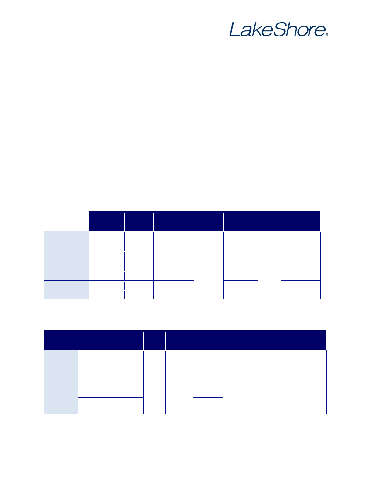
Temperature Limits
The maximum temperature limits for the multiple stages and components of the probe station are listed below.
Adhere to these limits at all times during probe station operation.
Vacuum, Probing and Sample Operation
Follow the procedures in Chapter 4 of the EMPX-HF manual for information about vacuum operation, manipulating
the probe arm stages, sample exchange and imaging/probing the sample.
Temperature Operation
The cooling engine in the CRX-EM-HF is a two stage closed cycle refrigerator (CCR). The sample stage and probe
holders are thermally connected to the CCR 2nd stage through vibration isolation: the radiation shield stage and
probe arms are thermally connected to the CCR 1st stage through similar vibration isolation. The CRX-EM-HF is
capable of operating the sample stage to 400 K; however, to operate above 350 K, the probe holder thermal
anchors must be removed from the sample stage in order to avoid raising the probe temperatures to above their
350 K maximum temperature.
The recommended operation for variable temperature measurements is to allow the entire CRX-EM-HF station to
cool to base temperature and then to warm the sample stage to the desired measurement setpoint.
Controls for Temperature Operation
The CCR compressor and cold head in the CRX-EM-HF are identical to those used in the CRX-4K probe station.
Refer to section 4.5.1 of the CRX-4K manual for information about CCR and electronic controls in the CRX-EM-HF.
Cooling the Probe Station to Base Temperature
For station cooldown, follow the procedure in section 4.5.2 of the CRX-4K manual to cool the probe station.
Operating the Sample Stage from Base Temperature to 350 K
To operate the CRX-EM-HF from base temperature to 350 K, follow the procedure in section 4.5.3 of the CRX-4K
manual; however, use the sample stage controller settings given in Table 7 of this document to set P, I, and D and
the proper heater range settings for the temperature setpoint.
Operating the Sample Stage from 350 K to 400 K
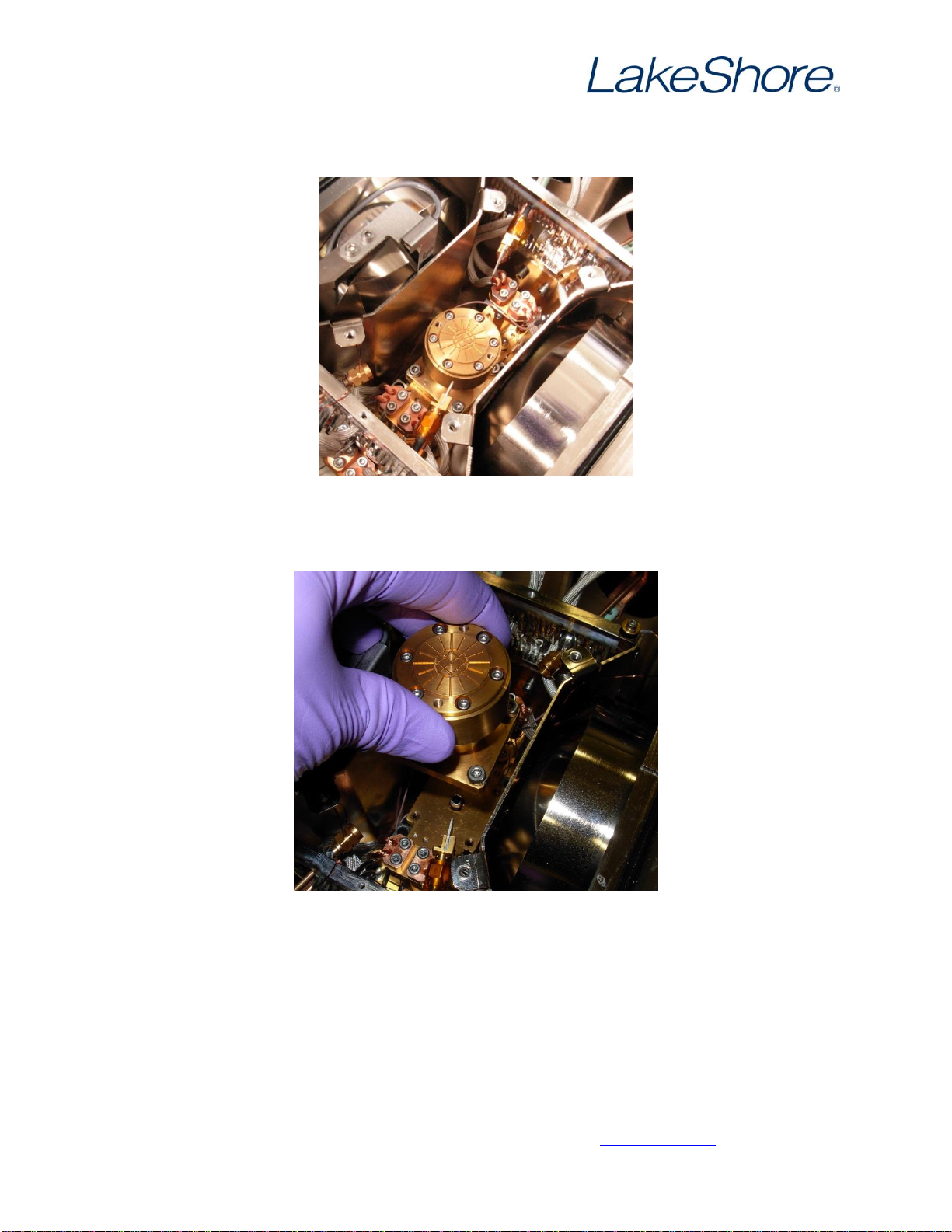
To operate the CRX-EM-HF from 350 K to 400 K, use Chapter 4 of the EMPX-HF manual as a guide to remove the
probe holder thermal anchors from the sample stage. The thermal anchors can be left loose in the probe station or
tied to the probe arm using simple string or unwaxed dental floss. Follow the procedure in section 4.5.3 of the
CRX-4K manual; however, use the sample stage controller settings given in Table 7 of this document to set P, I, and