Lakeside 000010 Quick setup guide

Shore Ramp DIY Kit p/n: 000010 rev A 1 doc: 400010 copyright© 2022 Lakeside Recreation, LLC
Shore Ramp DIY Wood Kit
Assembly & Use Instructions
p/n: 000010
Lakeside Recreation LLC
www.shoreramp.com
Additional Materials Needed
The Shore Ramp DIY Kit is designed to be assembled using pressure-treated lumber purchased separately by the
customer from a local lumber yard or home improvement store such as Home Depot, Menards, Lowes, etc.
The Kit uses the following quantities and sizes of pressure-treated lumber:
QTY Size Length
2 2x6 12’
1 2x4 6’ (cut into two 3’ pieces)
1 4x4 4’ (likely need to purchase 8’ and cut)
Tools Needed
The following tools will be necessary or useful to fabricate and assemble the Shore Ramp DIY Kit.
Wood Saw with blade suitable for cross cutting the 2x4’s, the 4x4, and the angled rip cuts in the 2x6’s:
3/8” Drill Bit, 3/4” Drill Bit, 1-1/8” Drill Bit (Spade style recommended)
Drill
Drill-Guide or a Drill-Press (recommended for uniform, precisely-bored holes).
9/16” box wrench + 9/16” socket wrench.
Rubber mallet.
Medium to large pliers with good gripping teeth (linesman’s pliers recommended).
Measuring Tape
Marking Pencil & Straight edge
Square
Clamps
Belt Sander or hand Sanding Block with course sandpaper

Shore Ramp DIY Kit p/n: 000010 rev A 2 doc: 400010 copyright© 2022 Lakeside Recreation, LLC
Cutting
Measure and cross-cut a piece of the 4x4 48” long. This piece should be free of any large knots which could weaken it.
This piece will become the “Winch Strut”. (Using a 7” Circular saw will require cutting from both sides to get all the way
through.)
Measure and cross-cut two pieces of the 2x4 36” long. These pieces will become the “Front Foot” and “Rear Foot”.
Mark the angled cuts on the top, rear ends of the 2x6 sides by measuring 7” along the top edge, and 1-¼” down the end
and marking with a straight edge. Cut using a suitable saw.
Sanding (Recommended)
Sand to clean up the angled cuts on the 2x6’s. Add a radius to the edges of the cut and around the ends so as to avoid
any sharp edges that could contact your PWC.
Sand a radius on the edges of the cut ends of the 2x4 Rear Foot and Front Foot to avoid any sharp edges that could get
stepped on by bare feet.
4x4’s typically do not come with radius corners. Sand a radius on the corners and the edges of the cut end of the Winch
Strut to avoid any sharp edges near the winch handle.
Mark & Drill the Axle Holes in the 2x6 Sides
To avoid later confusion on which is the outside face of the sides, lay them down alongside each other with inner faces
down, the top edges next to each other, and the two cut corners next to each other. Mark the outer face.
Measure 9” in from the end of the 2x6 Side with the angled cut to the first hole. After that, the 8 total holes are spaced
every 16”. For best results, align the two sides and mark them together. Each axle hole is ¾” from the top edge.
Use a ¾” drill bit. These holes will need to be precisely perpendicular for best results and ease of assembly. Using a Drill
Guide or even a Drill Press is strongly recommended to ensure these holes are bored precisely perpendicular. To avoid
chipping that could interfere with wheel rotation, drill from the outside face.

Shore Ramp DIY Kit p/n: 000010 rev A 3 doc: 400010 copyright© 2022 Lakeside Recreation, LLC
Mark & Drill the 2x6 Sides to Connect the Plates
Hold (clamp) the End Roller Plate aligned with the edges of its outer sides even with the end of the 2x6 Side and the
bottom surface aligned with the bottom inner edge of the 2x6 Side. Use a square to ensure the plate is square with the
bottom of the 2x5 Side. Mark the 3/8” holes and also trace the location of the elliptical 5/8” hole on the inner face of
the 2x6 Side. Unclamp and drill the 3/8” Holes from the inside face of the 2x6 Sides.
For the Strut Mount Plate, hold (clamp) the 2x6 Side to the angled side of the plate, aligned with the front end of the 2x6
Side and the bottom surface aligned with the bottom inner edge of the 2x6 Side. Use a square to ensure the plate is
square with the bottom of the 2x5 Side . Mark the holes on the inside face of the 2x6 Side. Unclamp and Drill the 3/8”
Holes from the inside face of the 2x6 Sides. Repeat for the other side.
In addition, use the ¾” drill bit to make a clearance pocket ¾” deep on each inside face where the 5/8” elliptical hole is
located. Angle the drilling to approximately match the angle of the shaft that will be inserted. Repeat for the other Side.
Check the clearance with the shaft and both sides.
To locate the Lateral Plate, measure 8-½” from the front edge of the 2x6 Side and make a mark. Using a square to mark
a square line will aid with alignment. Align the Lateral Plate front edge (the angled tongue faces to the front) to the
marked line. Align the bottom of the plate to the bottom edge of the 2x6 Side. Mark the holes. Drill the 3/8” Holes
from the inside face. Repeat for the other Side.

Shore Ramp DIY Kit p/n: 000010 rev A 4 doc: 400010 copyright© 2022 Lakeside Recreation, LLC
Assemble The Axles & Sides
Bolt the End Roller Plate and Strut Mount Plate to the one Side (with Washers on the outside surface of the wood) Start
the Nuts, but don’t tighten yet.
Also assemble The 10” Roller into the End Roller Plate with a Spacer on each side and the 5/8” Shaft inserted at this
time.
Insert each of the 8 Bent Axles apx 2” through the Side.
Starting with one end, start inserting the first axle into the other side, but don’t push it through. Get the next axle
started into its hole and so-on, working down the length until all the axles are started in their holes.
Work the two sides closer together on the axles until the Sides are tight to the plates and the Axles are all centered. A
rubber mallet (or scrap of 2x4) will be useful to persuade the side to slide onto all the axles and center the axles.
Insert the Bolts (with Washers) through the other Side and get the Nuts started.
Before tightening the Bolts, also get Lateral Plate in place and those 4 sets of bolts started.
Once all the Bolts are in place and the Nuts are started, they can all be tightened. Tighten them to the point of
compressing the wood slightly.

Shore Ramp DIY Kit p/n: 000010 rev A 5 doc: 400010 copyright© 2022 Lakeside Recreation, LLC
Mark, Drill, and Assemble The Feet
Set the partially-assembled Shore Ramp on the Rear Foot and Front Foot. Align each foot to the front edge of each plate
and center them left to right. Mark the holes. Drill the 3/8” marked holes. Assemble each with 2 sets of Bolt, Washer,
and Nut. Insert the Bolt from the bottom with the Washer against the wood and the nut on the inside of the Plates.
Tighten.
Attach the Winch Strut & Winch
Temporarily clamp the Winch Strut on the mounting locations on the Strut Mount Plate and Lateral Plate. Mark the hole
locations through the tongue of the Lateral plate from below. Unclamp and drill the 3/8” holes from the bottom of the
Winch Strut. Also mark and drill the hole locations for the winch from the top of the Winch Strut as shown.
Using the 1-1/8” drill bit, Counter-bore the four bolt holes on the top of the Winch Strut 1/2” inch deep (and no more
than 3/4” inch deep). This will prevent the bolt heads from damaging the underside of the PWC should it be pulled all
the way up to contact the winch strut. Also counter-bore the holes to mount the winch on the bottom side of the winch
strut the same 1-1/8” dia x 1/2” deep. The 4.00” long bolts provided are the proper length when used with the counter-
bored holes.

Shore Ramp DIY Kit p/n: 000010 rev A 6 doc: 400010 copyright© 2022 Lakeside Recreation, LLC
Assemble the Winch Strut using 4 sets of Bolts, Washers, and Nuts through the Lateral Plate and Strut Plate. The
Washers should be on the wood side of the joint in the counter-bores.
Assemble the Winch to the Winch Strut using 2 sets of Bolts, Washers, and Nuts. It may be helpful to unwind some
amount of the strap to better access the holes on the inside bottom of the winch. Washers are provided for both ends
of these bolts as the winch may have slotted mounting holes.
Assemble the Winch handle using the provided lock nut.
Add the Wheels
Place a 3/4” washer and then a wheel on each of the axle ends and secure with a cotter pin through the hole.
The cotter pins can be bent most effectively with a large pliers with teeth gripping just the longer tail and twisting.
A slight bend of 15 degrees is sufficient to retain the pin while still allowing for easy removal if necessary.

Shore Ramp DIY Kit p/n: 000010 rev A 7 doc: 400010 copyright© 2022 Lakeside Recreation, LLC
Installation
The Shore Ramp is intended for the storage of personal watercraft on gently sloping firm sand, soil, or turf.
Place the Shore Ramp with the Rear Foot just in the water so that the rear set of rollers is just submerged. This should
allow the watercraft to be easily floated up to the first roller and then winched up and onto the ramp. Some
experimentation and adjustment may be required to determine the optimal location.
The edge of the Rear Foot of the Shore Ramp must be firmly supported by the lakebed to prevent any back-sliding. The
Front Foot must be supported on firm soil, level across its entire width to prevent any side tipping.
CAUTION: Do not use the Shore Ramp on loose rock or unstable ground where it may slide down or tip to the side.
Loading a watercraft onto the Shore Ramp:
Manually unwind the strap until the hook can reach just past the end of the ramp.
Float the watercraft by hand to the front of the ramp. Attach the winch strap to the bow loop.
Engage the winch control such that it is ratcheting in the wind-up direction.
Wind the winch, pulling the front of the watercraft to the first set of rollers. Guide the watercraft so that it remains
centered and aligned with the ramp (in windy conditions this may be easier with two people).
As the watercraft comes up and over the first roller, confirm the watercraft is not rubbing on the Shore Ramp.
Wind the winch until the watercraft is pulled all the way up the ramp.
IMPORTANT: Do not operate your watercraft in the shallows or attempt to power it up the ramp as the PWC’s
impeller will be damaged by sand and rocks pulled in from the bottom. Always float your watercraft to and from
deeper water by hand. Consult your PWC owner’s manual for the minimum safe operating depth.
IMPORTANT: Always ensure the winch ratchet is engaged to hold the load before releasing the handle.
CAUTION: Do not exceed the weight and size capacity of the Shore Ramp (1200 lbs or 54” wide).
CAUTION: Do not use the Shore Ramp if any part of the ramp, winch, or winch strap is damaged, cracked, rotted,
worn, or malfunctioning.
Launching a watercraft from the Shore Ramp:
Take up the load on the winch by grasping the handle.
While staying in control of the load, disengage the ratchet control to allow the winch to unwind.
Slowly unwind the winch, staying at all times in control of the load by firm hold of the winch handle.
When the watercraft is completely off the ramp and floating in the water with slack in the strap, unhook the strap.
Float your watercraft by hand to the minimum safe operating depth before starting the engine.
CAUTION: Should the winch handle be released under load, keep clear of the rapidly spinning handle. Although not
ideal, it is safest to then just allow the winch to unwind until the PWC comes to rest in the water.

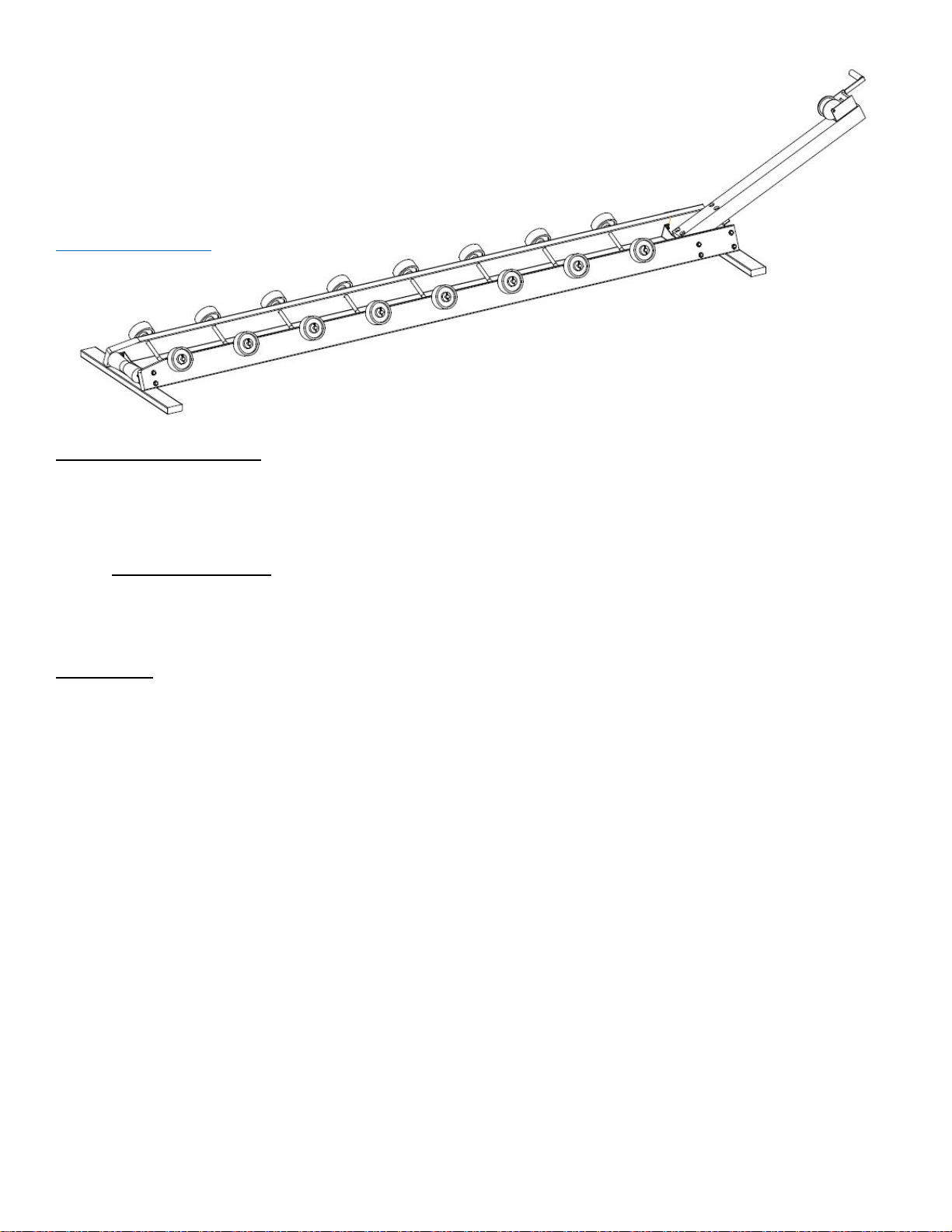
Shore Ramp DIY Kit p/n: 000010 rev A 8 doc: 400010 copyright© 2022 Lakeside Recreation, LLC
Parts List
Part Number Qty Description
100001 16 Wheel, 5 x 2 Polyolefin
100002 1 Which with Strap
700004 8 Bent Aluminum Axle
700005 1 5/8” Roller Shaft, Galvanized
730007 1 10” Keel Roller
700003 1 Roller End Plate, Galvanized
700002 1 Strut Mount Plate, Galvanized
700001 1 Lateral Plate, Galvanized
1 Bolt Bag Containing:
730001 16 3/8-16 x 2.50” Galvanized Bolt
730002 6 3/8-16 x 4.00” Galvanized Bolt
730004 22 3/8-16 Galvanized Nut
730003 24 3/8 Galvanized Washer
730006 16 3/4" Nylon Washer
730005 2 5/8” Shaft Spacer
300001 16 Cotter Pins
400010 1 Instructions for Shore Ramp DIY Kit, Printed
400011 1 Label for Box for Shore Ramp DIY Kit, Printed
710001 1 Shipping Box Shore Ramp DIY Kit
One Year Limited Warranty
LAKESIDE RECREATION products are warranted to be free from defects in materials or workmanship for one (1) year from the date
of purchase. Within this period we will provide a replacement for any component that fails in normal use. Such replacement will be
made at no charge to you, provided that you shall be responsible for any shipping charges and labor for replacement of the component.
Replacement products or components may be new or refurbished at the sole discretion of LAKESIDE RECREATION.
This warranty does not apply to: (a) cosmetic condition, such as (but not limited to) scratches, markings, discoloration, nicks, dirt, oil,
stains, surface corrosion, and dents; (b) damage or loss caused by accident, abuse, misuse, or other acts of nature or external causes;
(c) damage or failure due to improper assembly, improper installation, overloading beyond rated capacity, or use for purposes not
intended; (d) damage to a product resulting from modification or alteration. Determination of defects in material or workmanship
which are covered under this warranty shall be at the sole discretion of LAKESIDE RECREATION.
To make a warranty claim, contact LAKESIDE RECREATION via the warranty claim link on www.lakesiderecreation.com and
provide a description of the failed component and your contact and shipping information. LAKESIDE RECREATION at its sole
discretion may require photographic documentation of the failed component; require the failed component to be returned for
inspection; and/or require the failed component to be returned in exchange for the replacement component. Returned components
shall be become the property of LAKESIDE RECREATION when a replacement component is provided. Please do not return any
products or components without prior authorization. LAKESIDE RECREATION shall not be responsible for any shipping charges
for any component or product returned to us, nor for any shipping charges to return back to you any component or product.
THE WARRANTIES AND REMEDIES CONTAINED HEREIN ARE EXCLUSIVE AND IN LIEU OF ALL OTHER
WARRANTIES EXPRESS, IMPLIED, OR STATUTORY, INCLUDING ANY LIABILITY ARISING UNDER ANY WARRANTY
OF MERCHANTABILITY OR FITNESS FOR A PARTICULAR PURPOSE, STATUTORY OR OTHERWISE. Subject to
applicable law, in no event shall our liability exceed the purchase price of the product.
Table of contents
Other Lakeside Boating Equipment manuals
Popular Boating Equipment manuals by other brands

Mercury
Mercury Axius System user manual

Big Air
Big Air Fusion Tower Installation and instruction manual

Doyle Sailmakers
Doyle Sailmakers Cradle Cover manual

CoverCraft
CoverCraft CARVER Bimini Top Installing

Harken
Harken Performa 20.2 PTP Installation and maintenance manual

Sunstream
Sunstream FL15023 Assembly manual

MINN KOTA
MINN KOTA PRECISION MK 106PCL owner's manual

Dowco
Dowco V324SE installation instructions

NVequipment
NVequipment ACCESS NOT02848 user manual

ShoreLand'r
ShoreLand'r ShoreLock'r TA0134 quick guide

Seamax
Seamax Reborn Pro installation guide

Ultraflex
Ultraflex UC 81 Installation and maintenance manual