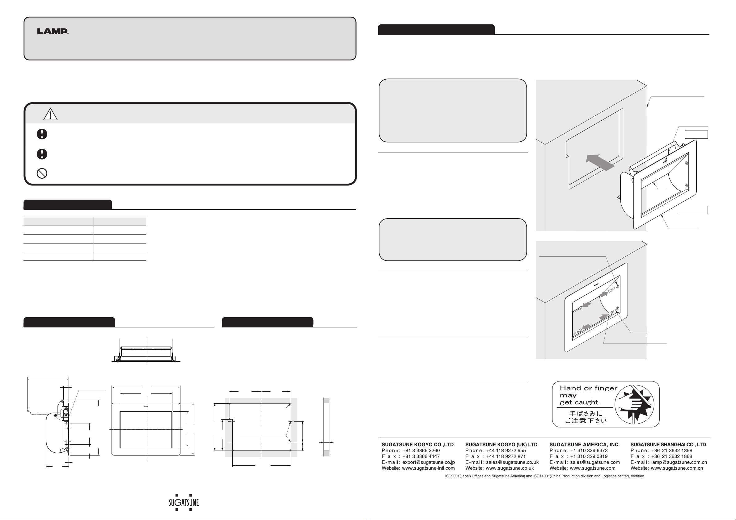
Installationprocedure
1.
Inserttheflaplidbodyinthecutoutofthe
mountingsurface.
2.
Havingopenedthelid,insertthescrews
throughtheprovidedaccessscrewholes
(2oneachside)andfastentheflaplidbody
securely.
3.
Slowlyopenandclosethelidcompletelya
fewtimesinordertomakesurethatthereare
noobstaclessuchasthebottomedgeofthe
cutoutoranyiteminside.
4.
Coverthescrewdriveraccessholeswiththe
capsprovided.
5.
Pastthewarningstickerinavisibleposition
toavoidanyinjurywhenusingtheAZ-GD230.
AZ-GD230STAINLESSSTEELDAMPENEDFLAPLIDSYSTEM
Installationinstructions
Partsdescription
Dimensiondrawing
Thankyouforpurchasingthisstainlesssteel,dampenedflapsystem.Pleasereadtheseinstructionscarefully
foraproperinstallation.
●Installationscrewsarenotincluded(4screwsneeded).Typeandlengthofthescrews
shouldbedecidedbytakingthetypeofsupportintoconsideration.
WerecommendtheuseofTappingST3screwsnominal3.
Description Quantity
Flaplidbody 1
Installationinstruction 1
Warningsticker 1
Accessholecovercaps 4
Cutout:frontview Cutout:sideview
Installationsurface
LAMPlogo
AZ-GD230
Accessholecovercap
Screwdriveraccesshole
Lid
TOP
BOTTOM
Screw
Cutoutdimensions
!IMPORTANT:
・MakesurethattheLAMPlogoisatthe
top.
・Donotleaveanygapbetweentheflap
lidbodyandthemountingsurface
!IMPORTANT:
・Makesurethatthefinalassemblyis
securelyfastened.
SUGATSUNE
SUS304
4×φ3.5 holes
forinstallation
screws
10
100
308
160
234
234
(1.5)
(22.6)
whenflapat 90˚
(249) whenflapat 90˚
(184.7)
whenflapat 90˚
9549
18〜22mm
265 +1
0
142
215
39 95
5×R6 Max
AZ-GD230
Mountingscrewholes
TheAZ-GD230isdesignedtofunctionwheninstalledverticallyasshownbelow.Horizontal,slantedor
upsidedowninstallationwillresultinimproperfunctionandmaybeleadtoinjury.
Toavoidanyriskofaccidentalfall,ensurethattheAZ-GD230issecurelyfastenedtoitssupport.
Anyattempttodismantle,modifyoruseinanywayotherthanthatindicatedbelow,mayresultin
damageorinjury.
CAUTION Ifthesecautionsarenotfollowed,itmayresultininjuryordamage.