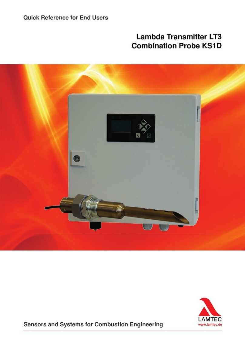
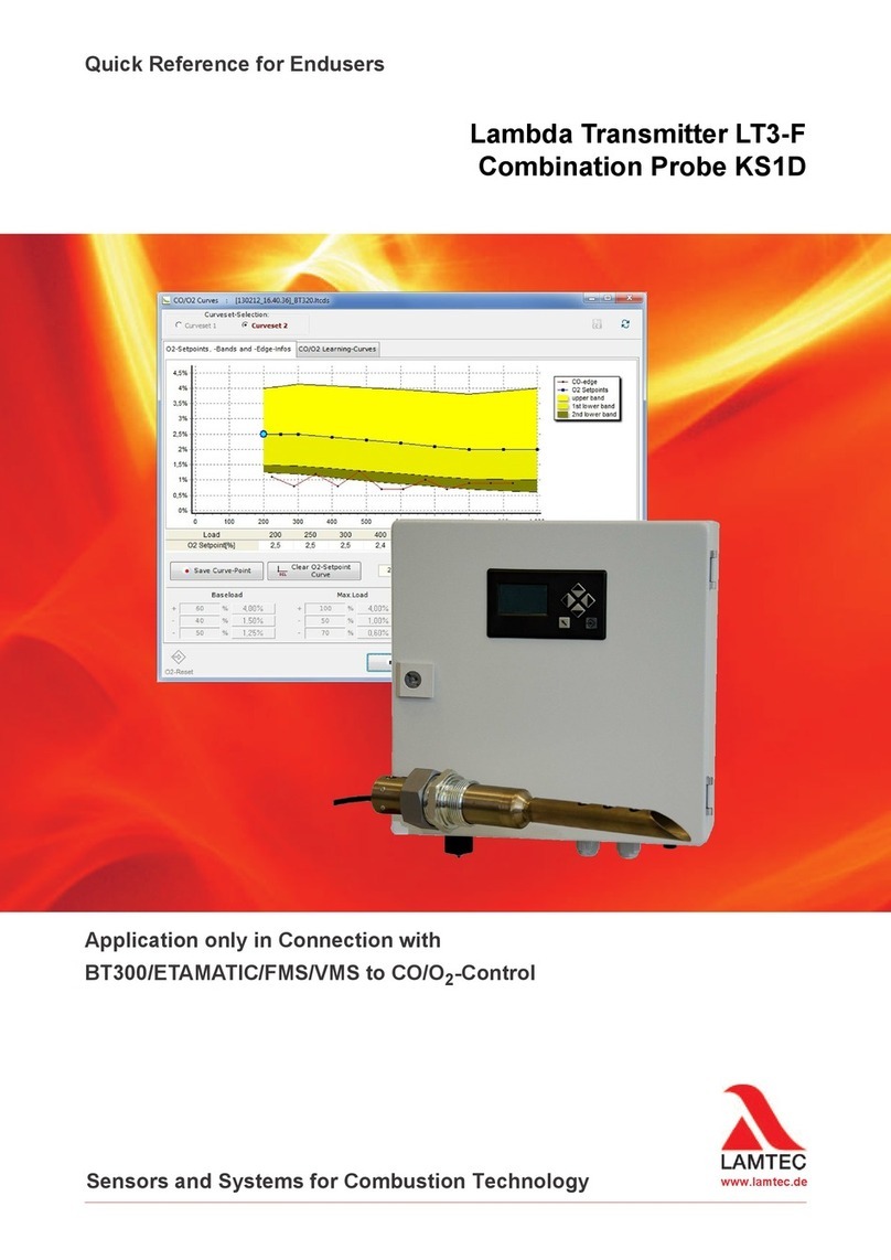
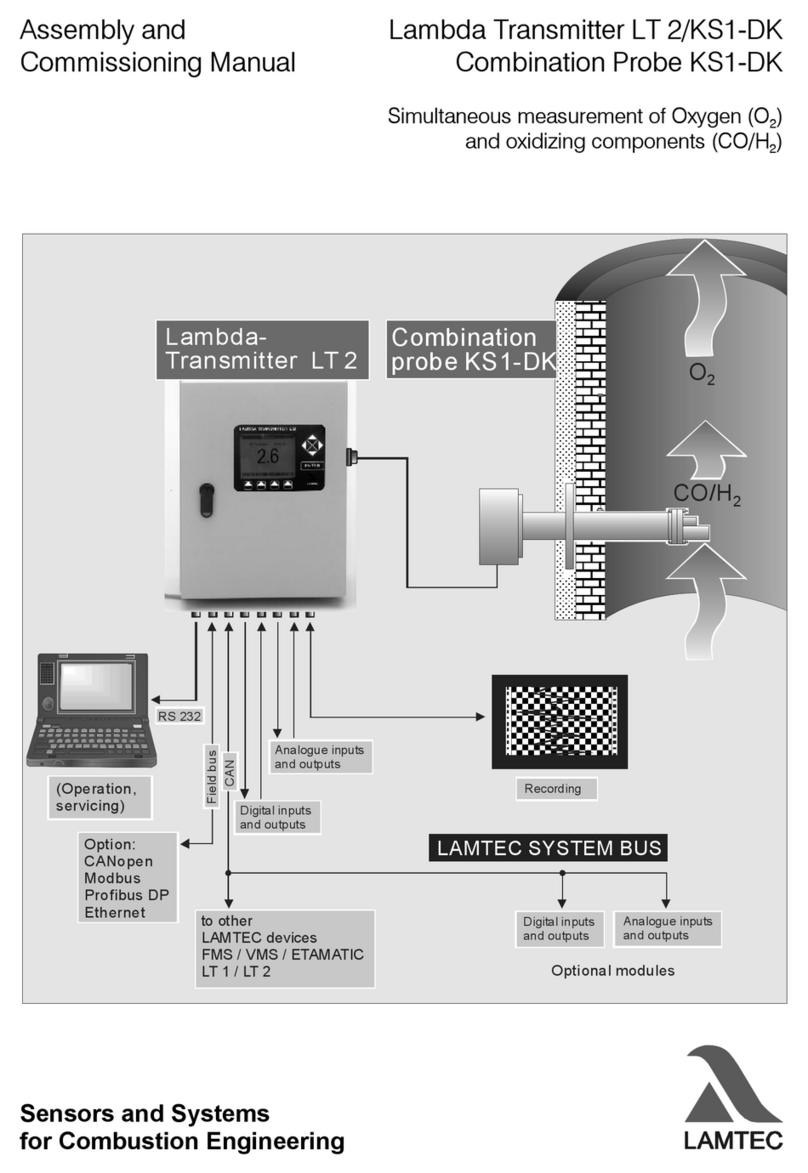
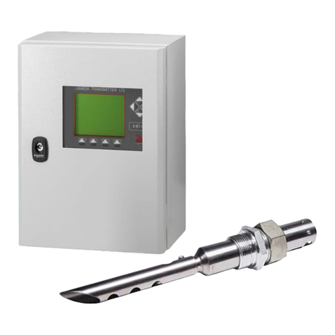
Lamtec Lambda LS2-K User manual

www.lamtec.de
Sensors and Systems for Combustion Engineering
Quick Reference for End Users
Lambda Transmitter LT2-K
Lambda Probe LS2-K/LS2KV


2
Table of Contents
Table of Contents
1 Important Information about the Manual . . . . . . . . . . . . . . . . . . . . . . . . . . . . . . . . . . . . . . . . 5
1.1 Validity of these Instructions. . . . . . . . . . . . . . . . . . . . . . . . . . . . . . . . . . . . . . . . . . . . . . . 5
1.2 Information on Using this Operating Manual . . . . . . . . . . . . . . . . . . . . . . . . . . . . . . . . . . 5
1.3 Glossary. . . . . . . . . . . . . . . . . . . . . . . . . . . . . . . . . . . . . . . . . . . . . . . . . . . . . . . . . . . . . . 5
2 For Your Safety. . . . . . . . . . . . . . . . . . . . . . . . . . . . . . . . . . . . . . . . . . . . . . . . . . . . . . . . . . . . . 6
2.1 Classification of the Safety Instructions and Warnings . . . . . . . . . . . . . . . . . . . . . . . . . . 6
2.2 Proper Use - Conditions of Use . . . . . . . . . . . . . . . . . . . . . . . . . . . . . . . . . . . . . . . . . . . . 7
2.3 Permissible Users . . . . . . . . . . . . . . . . . . . . . . . . . . . . . . . . . . . . . . . . . . . . . . . . . . . . . . 7
2.4 Safety Equipment/Safety Measures. . . . . . . . . . . . . . . . . . . . . . . . . . . . . . . . . . . . . . . . . 8
2.5 Protection Against Emissions from Gas Carrying Channels . . . . . . . . . . . . . . . . . . . . . . 9
2.6 Commissioning/Decommissioning . . . . . . . . . . . . . . . . . . . . . . . . . . . . . . . . . . . . . . . . . 10
2.6.1 Decommissioning, Storage and Commissioning . . . . . . . . . . . . . . . . . . . . . . . . 10
2.6.2 Environmental Protection, Waste Disposal . . . . . . . . . . . . . . . . . . . . . . . . . . . . 10
3 Technical Description . . . . . . . . . . . . . . . . . . . . . . . . . . . . . . . . . . . . . . . . . . . . . . . . . . . . . . 11
3.1 LT2-K LS2-K Structure in Principle . . . . . . . . . . . . . . . . . . . . . . . . . . . . . . . . . . . . . . . . 11
3.2 LT2-K LS2-KV Structure in Principle . . . . . . . . . . . . . . . . . . . . . . . . . . . . . . . . . . . . . . . 12
3.3 LS2-K / LS2-KV Lambda Probe . . . . . . . . . . . . . . . . . . . . . . . . . . . . . . . . . . . . . . . . . . . 13
3.4 LT2-K Lambda Transmitter. . . . . . . . . . . . . . . . . . . . . . . . . . . . . . . . . . . . . . . . . . . . . . . 15
3.5 LT2-K Lambda Transmitter Type 657R102 with Display and Operating Unit. . . . . . . . . 16
3.6 Display and Operating Unit . . . . . . . . . . . . . . . . . . . . . . . . . . . . . . . . . . . . . . . . . . . . . . 17
3.7 Cold-start Delay . . . . . . . . . . . . . . . . . . . . . . . . . . . . . . . . . . . . . . . . . . . . . . . . . . . . . . . 18
3.8 Analogue Outputs 0/4 … 20 mA, 0/2 … 10 V . . . . . . . . . . . . . . . . . . . . . . . . . . . . . . . . 18
3.9 Digital Outputs . . . . . . . . . . . . . . . . . . . . . . . . . . . . . . . . . . . . . . . . . . . . . . . . . . . . . . . . 19
3.10 Analogue Inputs (Optional) . . . . . . . . . . . . . . . . . . . . . . . . . . . . . . . . . . . . . . . . . . . . . . 20
3.11 Digital Inputs . . . . . . . . . . . . . . . . . . . . . . . . . . . . . . . . . . . . . . . . . . . . . . . . . . . . . . . . . 20
4 Commissioning/Decommissioning . . . . . . . . . . . . . . . . . . . . . . . . . . . . . . . . . . . . . . . . . . . 21
4.1 Display and Operating Unit of the LT2-K Lambda Transmitter. . . . . . . . . . . . . . . . . . . . 21
4.2 Monitor Output . . . . . . . . . . . . . . . . . . . . . . . . . . . . . . . . . . . . . . . . . . . . . . . . . . . . . . . . 21
4.3 Internal Display and Operating Elements . . . . . . . . . . . . . . . . . . . . . . . . . . . . . . . . . . . 22
4.4 Display and Operating Unit Type 657R0831 (Option) . . . . . . . . . . . . . . . . . . . . . . . . . . 23
4.4.1 Display . . . . . . . . . . . . . . . . . . . . . . . . . . . . . . . . . . . . . . . . . . . . . . . . . . . . . . . . 24
4.4.2 Menu Function 'meas' . . . . . . . . . . . . . . . . . . . . . . . . . . . . . . . . . . . . . . . . . . . . 25
4.4.3 Menu Function 'cal' . . . . . . . . . . . . . . . . . . . . . . . . . . . . . . . . . . . . . . . . . . . . . . 25
4.4.4 Menu Function 'par' . . . . . . . . . . . . . . . . . . . . . . . . . . . . . . . . . . . . . . . . . . . . . . 27
4.4.5 Menu Function 'psw' . . . . . . . . . . . . . . . . . . . . . . . . . . . . . . . . . . . . . . . . . . . . . 28
4.4.6 Menu Function 'view' . . . . . . . . . . . . . . . . . . . . . . . . . . . . . . . . . . . . . . . . . . . . . 28
4.4.7 Menu Function 'change'. . . . . . . . . . . . . . . . . . . . . . . . . . . . . . . . . . . . . . . . . . . 30
4.4.8 Menu Function 'diag' . . . . . . . . . . . . . . . . . . . . . . . . . . . . . . . . . . . . . . . . . . . . . 31
4.4.9 Limit values display and resetting . . . . . . . . . . . . . . . . . . . . . . . . . . . . . . . . . . . 32
4.4.10 Display of the Limit Value Crossing . . . . . . . . . . . . . . . . . . . . . . . . . . . . . . . . . . 33
4.4.11 Brightness, Contrast and Language . . . . . . . . . . . . . . . . . . . . . . . . . . . . . . . . . 34
4.4.12 Customer Password Input . . . . . . . . . . . . . . . . . . . . . . . . . . . . . . . . . . . . . . . . . 35
4.5 Menu Overview . . . . . . . . . . . . . . . . . . . . . . . . . . . . . . . . . . . . . . . . . . . . . . . . . . . . . . . 36
4.5.1 LT2-K Calibration Menu . . . . . . . . . . . . . . . . . . . . . . . . . . . . . . . . . . . . . . . . . . . 36
4.5.2 LT2-K Diagnosis Menu . . . . . . . . . . . . . . . . . . . . . . . . . . . . . . . . . . . . . . . . . . . 37
4.5.3 LT2-K Measurement Menu . . . . . . . . . . . . . . . . . . . . . . . . . . . . . . . . . . . . . . . . 38

3
Table of Contents
4.5.4 LT2-K Parameter Menu . . . . . . . . . . . . . . . . . . . . . . . . . . . . . . . . . . . . . . . . . . . 39
4.6 Factory Settings . . . . . . . . . . . . . . . . . . . . . . . . . . . . . . . . . . . . . . . . . . . . . . . . . . . . . . . 40
4.6.1 Device Configuration . . . . . . . . . . . . . . . . . . . . . . . . . . . . . . . . . . . . . . . . . . . . . 40
4.6.2 Jumpers . . . . . . . . . . . . . . . . . . . . . . . . . . . . . . . . . . . . . . . . . . . . . . . . . . . . . . . 40
4.7 Measurement Start-up . . . . . . . . . . . . . . . . . . . . . . . . . . . . . . . . . . . . . . . . . . . . . . . . . . 41
4.7.1 Measurement with LS2-K . . . . . . . . . . . . . . . . . . . . . . . . . . . . . . . . . . . . . . . . . 42
4.7.1.1 Adjust the Amount of the Reference Air. . . . . . . . . . . . . . . . . . . . . . . . . . . . . . . 44
4.7.1.2 Performing an offset calibration to ambient air . . . . . . . . . . . . . . . . . . . . . . . . . 45
4.7.1.3 Performing an Offset Calibration with Compressed Air . . . . . . . . . . . . . . . . . . . 46
4.7.1.4 Perform a Calibration with Reference Measurement. . . . . . . . . . . . . . . . . . . . . 47
4.7.1.5 Perform a Calibration with Test Gas . . . . . . . . . . . . . . . . . . . . . . . . . . . . . . . . . 48
4.7.2 LS2-KV Measurement (Fully-automatic Calibration) . . . . . . . . . . . . . . . . . . . . . 49
4.7.2.1 Adjust the Amount of the Reference Air. . . . . . . . . . . . . . . . . . . . . . . . . . . . . . . 50
4.7.2.2 Performing an offset calibration to ambient air . . . . . . . . . . . . . . . . . . . . . . . . . 51
4.7.2.3 Reference measurement - Performing a Test Calibration . . . . . . . . . . . . . . . . . 52
4.7.2.4 Performing a Combined Offset and Test Gas Calibration . . . . . . . . . . . . . . . . . 53
4.8 Probe Certificate . . . . . . . . . . . . . . . . . . . . . . . . . . . . . . . . . . . . . . . . . . . . . . . . . . . . . . 54
4.9 Setting up Service Warnings . . . . . . . . . . . . . . . . . . . . . . . . . . . . . . . . . . . . . . . . . . . . . 55
4.10 Decommissioning. . . . . . . . . . . . . . . . . . . . . . . . . . . . . . . . . . . . . . . . . . . . . . . . . . . . . . 55
5 Test Certificate . . . . . . . . . . . . . . . . . . . . . . . . . . . . . . . . . . . . . . . . . . . . . . . . . . . . . . . . . . . . 56
6 Operation . . . . . . . . . . . . . . . . . . . . . . . . . . . . . . . . . . . . . . . . . . . . . . . . . . . . . . . . . . . . . . . . 57
6.1 Measurement During Distinct Pressure Surges at the Measuring Site . . . . . . . . . . . . . 57
6.2 Operational Failure, Switching On and Off. . . . . . . . . . . . . . . . . . . . . . . . . . . . . . . . . . . 57
6.3 Liquid Purification. . . . . . . . . . . . . . . . . . . . . . . . . . . . . . . . . . . . . . . . . . . . . . . . . . . . . . 57
7 Service and Maintenance . . . . . . . . . . . . . . . . . . . . . . . . . . . . . . . . . . . . . . . . . . . . . . . . . . . 58
7.1 Checking the O2Probe . . . . . . . . . . . . . . . . . . . . . . . . . . . . . . . . . . . . . . . . . . . . . . . . . 58
7.1.1 Calibrating the Air Voltage (Offset) . . . . . . . . . . . . . . . . . . . . . . . . . . . . . . . . . . 58
7.1.2 Checking (Calibration) with Reference Measurement /Test Gas . . . . . . . . . . . . 58
7.1.3 Fully-automatic Combined Calibration. . . . . . . . . . . . . . . . . . . . . . . . . . . . . . . . 59
7.2 Checking the Measurement Input of LT2-K . . . . . . . . . . . . . . . . . . . . . . . . . . . . . . . . . . 59
7.3 Checking the Probe's Internal Resistance Measurement . . . . . . . . . . . . . . . . . . . . . . . 59
7.4 Maintenance . . . . . . . . . . . . . . . . . . . . . . . . . . . . . . . . . . . . . . . . . . . . . . . . . . . . . . . . . 59
7.4.1 Checking the Measurement. . . . . . . . . . . . . . . . . . . . . . . . . . . . . . . . . . . . . . . . 59
7.4.2 Consumables. . . . . . . . . . . . . . . . . . . . . . . . . . . . . . . . . . . . . . . . . . . . . . . . . . . 59
7.4.3 Cleaning/Replacing the Sintered Metal Pre-filter. . . . . . . . . . . . . . . . . . . . . . . . 60
7.4.4 Replacing the O2Measuring Cell . . . . . . . . . . . . . . . . . . . . . . . . . . . . . . . . . . . 61
8 Fault Analysis/Trouble-shooting. . . . . . . . . . . . . . . . . . . . . . . . . . . . . . . . . . . . . . . . . . . . . . 63
8.1 Faults/Warnings . . . . . . . . . . . . . . . . . . . . . . . . . . . . . . . . . . . . . . . . . . . . . . . . . . . . . . . 63
8.2 Internal Fault Indication . . . . . . . . . . . . . . . . . . . . . . . . . . . . . . . . . . . . . . . . . . . . . . . . . 63
8.3 Warning Indication by LED Line. . . . . . . . . . . . . . . . . . . . . . . . . . . . . . . . . . . . . . . . . . . 64
8.4 Resetting Faults/Warnings . . . . . . . . . . . . . . . . . . . . . . . . . . . . . . . . . . . . . . . . . . . . . . . 65
8.5 Faults - Causes and Solutions . . . . . . . . . . . . . . . . . . . . . . . . . . . . . . . . . . . . . . . . . . . . 66
8.5.1 Probe voltage too low . . . . . . . . . . . . . . . . . . . . . . . . . . . . . . . . . . . . . . . . . . . . 66
8.5.2 Probe Heating Defective . . . . . . . . . . . . . . . . . . . . . . . . . . . . . . . . . . . . . . . . . . 66
8.5.3 Broken Wire Probe/Defective Probe . . . . . . . . . . . . . . . . . . . . . . . . . . . . . . . . . 66
8.5.4 No Probe Dynamics. . . . . . . . . . . . . . . . . . . . . . . . . . . . . . . . . . . . . . . . . . . . . . 67
8.5.5 Fault Analogue Output . . . . . . . . . . . . . . . . . . . . . . . . . . . . . . . . . . . . . . . . . . . . 67

4
Table of Contents
8.5.6 O2Value Is Incorrect . . . . . . . . . . . . . . . . . . . . . . . . . . . . . . . . . . . . . . . . . . . . . 68
8.5.7 Reference Air Is Missing . . . . . . . . . . . . . . . . . . . . . . . . . . . . . . . . . . . . . . . . . . 68
8.6 Warnings - Causes and Solutions . . . . . . . . . . . . . . . . . . . . . . . . . . . . . . . . . . . . . . . . . 69
8.6.1 LT2-K Calibration Menu . . . . . . . . . . . . . . . . . . . . . . . . . . . . . . . . . . . . . . . . . . . 69
8.6.2 Offset Voltage out of range . . . . . . . . . . . . . . . . . . . . . . . . . . . . . . . . . . . . . . . . 69
8.6.3 Reference Air Is Missing (Indication as a Warning in Parameter 395). . . . . . . . 69
8.6.4 Delta-P Offset/Test Gas Calibration is Insufficient - Too less Gas . . . . . . . . . . . 70
8.6.5 Delta-P Offset or Test Gas Calibration too High - Filter Clogged. . . . . . . . . . . . 70
8.6.6 Amount of Calibration Gas Insufficient . . . . . . . . . . . . . . . . . . . . . . . . . . . . . . . 70
8.6.7 Test Gas Calibration Is Invalid . . . . . . . . . . . . . . . . . . . . . . . . . . . . . . . . . . . . . . 71
8.6.8 Test Gas Calibration Is Invalid . . . . . . . . . . . . . . . . . . . . . . . . . . . . . . . . . . . . . . 71
8.6.9 Analogue Inputs 1/2/3/4 Input Value too Large/too Small . . . . . . . . . . . . . . . . . 71
8.6.10 Configuration Error at Analogue Outputs. . . . . . . . . . . . . . . . . . . . . . . . . . . . . . 71
8.6.11 Service Warning 1/Service Warning 2 . . . . . . . . . . . . . . . . . . . . . . . . . . . . . . . . 71
9 Spare Parts . . . . . . . . . . . . . . . . . . . . . . . . . . . . . . . . . . . . . . . . . . . . . . . . . . . . . . . . . . . . . . . 72
10 Appendix. . . . . . . . . . . . . . . . . . . . . . . . . . . . . . . . . . . . . . . . . . . . . . . . . . . . . . . . . . . . . . . . . 73
10.1 Electrical Connection . . . . . . . . . . . . . . . . . . . . . . . . . . . . . . . . . . . . . . . . . . . . . . . . . . . 73
10.2 Connection Diagram for LT2-K/LS2-K (semi automatic calibration). . . . . . . . . . . . . . . . 74
10.3 Connection Diagram for LT2-KV/LS2-KV (fully automatic calibration) . . . . . . . . . . . . . . 75
10.4 Electrical Connection . . . . . . . . . . . . . . . . . . . . . . . . . . . . . . . . . . . . . . . . . . . . . . . . . . . 76
10.5 Jumpers . . . . . . . . . . . . . . . . . . . . . . . . . . . . . . . . . . . . . . . . . . . . . . . . . . . . . . . . . . . . . 77
10.6 Fuses . . . . . . . . . . . . . . . . . . . . . . . . . . . . . . . . . . . . . . . . . . . . . . . . . . . . . . . . . . . . . . . 79
10.7 LT2 Power Electronic Type 657E1882 . . . . . . . . . . . . . . . . . . . . . . . . . . . . . . . . . . . . . . 80
10.8 Wet/Dry Measurement Deviations, Conversion Table . . . . . . . . . . . . . . . . . . . . . . . . . . 81
11 EU Declaration of Conformity . . . . . . . . . . . . . . . . . . . . . . . . . . . . . . . . . . . . . . . . . . . . . . . . 82

5
1 Important Information about the Manual
1.1 Validity of these Instructions
This manual describe the Lambda Transmitter LT2 with all required components. The informa-
tion in this document applies to the software version 1V61. If you utilise a different version, this
can lead to other effects to your device than those described in this manual.
The devices apply to the following standards and directives:
• DIN EN 61326-1: 2013-07
• DIN EN 61010-1: 2013-07
• 2014/35/EU Low Voltage Directive
• 2014/30/EU EMC Electromagnetic Compatibility
• 2011/65/EU RoHS
1.2 Information on Using this Operating Manual
NOTICE
Before starting work, you absolutely must read these instructions!
Carefully observe all warning notes!
They contain important data and information, the compliance with which will ensure the func-
tion of the device and, in turn, reliable measurement results.
The device described here corresponds with the standard configuration.
Particular attention must be paid to information and warnings. These are indicated by re-
spective pictograms. They serve to safeguard your personal safety and help you to avoid op-
erating errors.
This manual for end users contains the information required to operate and maintain the sys-
tem.
1.3 Glossary
Abbreviations
GED Gas extraction device
PCB Probe connection box
PIF Probe installation fitting
Li Limit values
IP Protection class for example IP54

6
2 For Your Safety
2 For Your Safety
2.1 Classification of the Safety Instructions and Warnings
The following symbols are used in this document to draw the user's attention to important safe-
ty information. They are located at points where the information is required. It is essential that
the safety information is observed and followed, and that applies particularly to the warnings.
DANGER!
This draws the user's attention to imminent danger. If it is not avoided, it will result in death or
very serious injury. The plant including its surroundings could be damaged.
WARNING!
This draws the user's attention to the possibility of imminent danger. If it is not avoided, it may
result in death or very serious injury. The plant including its surroundings could be damaged.
CAUTION!
This draws the user's attention to the possibility of imminent danger. If it is not avoided, it may
result in minor injuries. The plant including its surroundings could be damaged.
NOTICE
This draws the user's attention to important additional information about the system or system
components and offers further tips.
The safety information described above is incorporated into the instructions.
Thus, the operator is requested to:
1 Comply with the accident prevention regulations whenever work is being carried out.
2 Do everything possible within his control to prevent personal injury and damage to prop-
erty.

7
2 For Your Safety
2.2 Proper Use - Conditions of Use
The Lambda Transmitter LT2 in combination with the Lambda Probe LS2-K, is a universal sys-
tem for a direct detection of combustible gas constituents (CO/H2), displayed as an equivalent
of CO (COe) in combustion systems in superstoichiometric range (> 1).
The system is designed for semi-automatic calibration with air and test gas.
If the system should be used in a different way and the device function can not be accurately
determined for this application, you must consult the manufacturer before.
Prerequisites
All planning, mounting, installation, commissioning, maintenance, and repair work must be
carried out by adequately trained personnel only and checked by experts.
Correct handling
in particular, it is necessary to ensure that
• the application must conform to the technical data and details of the permitted use, terms
and conditions with regards to mounting, connection, environment and operation (to be
taken from order documents, device’s user information, rating plat, etc) as well as the de-
livered documentation
• the local regulations and facility-specific and technical hazards must be noted and fol-
lowed.
• all necessary measures are taken to ensure value conservation, e.g. for transport and
storage as well as maintenance and inspection.
Observing the operating instruction
Intended use also includes:
• Observing all the information in the operating instructions.
• Carrying out all inspection and maintenance work.
2.3 Permissible Users
Qualified personnel
The person responsible for safety absolutely must guarantee that
• only qualified personnel perform work on the system parts.
Due to their training, education, experience, or instruction and due to their knowledge of
pertinent standards, provisions, accident prevention regulations, and system conditions,
qualified personnel are authorized to perform these tasks by the person responsible for
the safety of people and the system. It is decisive that this personnel must be able to rec-
ognise and prevent risks on time.
Experts are considered to be people according to DIN VDE 0105 or IEC 364 or directly
comparable standards like DIN 0832.
• These persons must have access to the provided operating manual and any pertinent or-
der-related documentation during all work and observe these documents within the scope
of preventing risks and damage.

8
2 For Your Safety
User groups
For the handling of the Lambda Transmitter LT2, three user groups are required:
• Service technicians of LAMTEC or its OEM customers and/or trained customer personnel:
– Qualified technicians/engineers have very good knowledge of the device.
– SERVICE access level - password-protected
• Operators, customer fitters, technicians for instrumentation and control technology, elec-
tricians, and electronic engineers have introductory knowledge of the device.
– CUSTOMER access level - password-protected
• Operating personnel with basic knowledge
– OPERATION access level - no password
2.4 Safety Equipment/Safety Measures
Hazards from electrical equipment
The LT2 Lambda Transmitter and the Lambda Probe is equipment for use in industrial electri-
cal power installations. Always switch off the power when working on mains connections or
mains voltage. If shrouding (for electrical safety) has been removed, reattach it before switch-
ing on the power supply again. Damage to health or equipment may result from improper use
or improper handling.
NOTICE
To avoid damage, always observe the respective security notices.
Preventive measures for improving operating safety
If the LT2 is used in conjunction with control and monitoring technology, the operator must en-
sure that any breakdown or failure of the LT2 device does not cause inadmissible damage or
dangerous operating states. To avoid faults which could cause direct or indirect personal or
material damage, the operator must ensure that:
• the responsible maintenance personnel can be reached at any time and as quickly as pos-
sible
• the maintenance personnel are trained to correctly respond to faults with the LT2 Lambda
Transmitter and the associated malfunctions
• in the case of doubt, the faulty equipment can be switched off immediately
• A switch-off does not lead to direct follow-up problems.
Avoiding consequential damages
To avoid consequential damages in the event of failure, which could cause direct or indirect
personal or material damage, the owner must ensure that qualified personnel can assess the
faults and initiate appropriate measures to tackle them.

9
2 For Your Safety
2.5 Protection Against Emissions from Gas Carrying Channels
Protect against gas leakage from the gas-bearing channel
The Lambda Probe LS2-K is fitted directly to the gas-bearing channel via a counterflange. If
the Lambda Probe LS2-K is dismantled, depending on the plant but particularly in the case of
excess pressure, aggressive and / or hot gas can seep out of the channel and this could pose
a serious health hazard to an unprotected operator if suitable safety measures have not be
taken previously. For prevention, suitable protective measures must be taken in advance.
WARNING!
Discharge of hot, corrosive gases!
In the event of high pressure and temperatures higher than 200 °C in the gas duct, gas es-
capes when the LS2-K Lambda Probe is removed.
Switch OFF the application before opening.
Wear protective clothing and a protective mask.
Affix appropriate warnings near by.
Close aperture immediately after finishing work.
WARNING!
Danger from electrical shock
The device contains live parts and touching these parts could cause electric shock.
Before opening the housing, disconnect the mains plug!

10
2 For Your Safety
2.6 Commissioning/Decommissioning
2.6.1 Decommissioning, Storage and Commissioning
The Lambda Transmitter and the Lambda Probe form a high quality electronic system. Treat
them with care at all times, including during shut-down, transport and storage.
Shut-down
NOTICE
Do not switch the Lambda Transmitter off as long as the Lambda Probe is mounted; including
when the relevant facility has been shut down. Residual gases cause corrosion and may dam-
age system parts.
Do not store the instruments outdoors without protection!
Always store in a dry place, if possible in the original packaging.
When dismantling, protect cable ends and plugs against corrosion and dirt. Corroded
plugs may cause malfunction.
If possible, transport in the original packaging.
WARNING!
Danger of burns!
If the probe is operated when removed, there is a danger of burns on the
probe housing.
Never lay the probe on flammable material and heat it up.
Wear protective gloves
Return to service
According to chapter 4 Commissioning/Decommissioning.
2.6.2 Environmental Protection, Waste Disposal
The design of Lambda Transmitter and LS2-K is also based on environmental considerations.
The modules can easily be separated and sorted into distinct types, and recycled accordingly.

11
3 Technical Description
3.1 LT2-K LS2-K Structure in Principle
Fig. 3-1 LT2 LS2-K system components.
In the case of the design with semi-automatic calibration device, the instrument air for offset
adjustment and the test gas must be connected to the probe by hand, one after the other, and
the necessary quantity must be set as well.
Pressure sensors are installed in the probe connection box and included in delivery.
A pump unit for reference air is available on request as an option if instrument air is not avail-
able.
NOTICE
A pump unit for reference air is necessary only if instrument air is not available!
1 Pre-filter type 650R2055
2 Counter flange DN65PN6 type 655R0179/0180
3 Lambda Probe LS2-K with semi-automatic calibration unit type 656R1030/1031/1032
4 Probe connection box (PCB)
5 Connection for offset/test gas calibration – 0.3 bar instrument air, test gas for example:
3vol. %O
2200 ppm CO 100 ppm H2in N2
6 Outlet port reference air
7 Reference air inlet, pressure reducer (on site) instrument air 0.3 bar or reference air pump 40 ... 60 l/h
8 Probe heater
9 Probe signal and pressure sensor
10 Flange seal Klinger Sil C-4400 type 655P4209
11 Measuring gas max. 400 °C/752 °F
Lambda Transmitter LT2-K type 657R102/103/104 in version 3K semi-automatic calibration
• A = in Wall mounting housing

12
3 Technical Description
3.2 LT2-K LS2-KV Structure in Principle
Fig. 3-2 System overview LT2-K LS2-KV
With the fully automatic calibrating unit, the instrument air (test gas 1) and the test gas (test
gas 2) can be permanently connected to the probe at 0.3 bar upstream pressure.
AComplete probe with counter flange and PCB
BLT2-KV Lambda Transmitter in wall mounting housing IP65 with integrated reference air pump (option),
type 657R102, steel sheet
1 LS2-KV Lambda Probe with fully automatic calibration unit type 650R2050/2051/650R2052
2 Sintered metal pre-filter type 650R2055
3 Counter flange DN65PN6 type 655R0179/0180
4 Flange seal Klinger Sil C-4400 type 655P4209
5 Reference air pump (option) type 657R1060, only necessary if there is no instrument air available.
6 Display and Operating Unit
7 Relay module, option for fully automatic calibration

13
3 Technical Description
3.3 LS2-K / LS2-KV Lambda Probe
The wiring between the LS2-K / KV Lambda Probe and the LT2-K Lambda Transmitter is done
with conventional, screened cables over terminal blocks; see the wiring diagram in chapter
10.2 Connection Diagram for LT2-K/LS2-K (semi automatic calibration)10.3 Connection Dia-
gram for LT2-KV/LS2-KV (fully automatic calibration)
Fig. 3-3 Lambda Probe LS2-K with semi-automatic
calibration
1 Probe connection box (PCB)
Fig. 3-4 Interior view of probe connection box LS2-K with semi-automatic calibra-
tion
1 Absolute pressure sensor
2 Differential pressure sensor
3 Throttle for calibration gas
4 Throttle for reference air
5 Stop cock for calibration gas
6 Hose connection for test gas
(instrument air 0.3 bar)
7 Air outlet
8 Hose connection for reference air
(instrument air 0.3 bar)
9 Electrical connection probe to LT2
probe connection
10 Electrical connection
absolute pressure sensor to LT2,
analogue input 2
11 Electrical connection
differential pressure sensor to LT2
analogue input 1

14
3 Technical Description
Fig. 3-5 Lambda Probe LS2-KV with connection
for fully-automatic calibration
1 Probe connection box (PCB)
Fig. 3-6 Interior view of probe connection box Lambda Probe LS2-KV with fully-auto-
matic calibration
1 Absolute pressure sensor
2 Differential pressure sensor
3 Solenoid valve 2 (shut-off valve)
4 Throttle for calibration gas
5 Solenoid valve 1 (shuttle valve)
6 Throttle for reference air
7 Hose connection for reference air
(instrument air 0.3 bar)
8 Outlet for reference air
9 Hose connection for test gas 1
(instrument air 0.3 bar)
10 Hose connection for test gas 2
(test gas 0.3 bar)
11 Electrical connection of probe
12 Electrical connection of
solenoid valves
13 Electrical connection of
differential pressure sensor
14 Electrical connection of absolute
sensor

15
3 Technical Description
3.4 LT2-K Lambda Transmitter
The LT2 Lambda Transmitter is the analysing unit for the LS2-K Lambda Probe. It contains all
the components required in order to operate the LS2-K Lambda Probe and to evaluate the
measurement signal. It also has additional analogue and digital inputs and outputs for sending
out measurement signals and for operating, status and limit value messages as well as serial
interfaces for connecting to a PC and for connecting to other LAMTEC devices. A universal
BUS interface for connecting to customers control systems is available as an option.
The following basic design is available:
• Wall-mounted housing made of sheet steel, lockable door at the front with impact-resistant
inspection window, IP65
Fig. 3-7 LT2 Lambda Transmitter in wall-mounted hous-
ing
in the following variant:
-Semi-automatic calibration and Display and operating
unit type 657R102

16
3 Technical Description
3.5 LT2-K Lambda Transmitter Type 657R102 with Display and Operating Unit
Fig. 3-8 Lambda Transmitter LT2-K Type 657R102
1 Transformer probe and elec-
tronic
2 Connection for Remote-Dis-
play-Software (Option)
3 Connecting cable with plug for
display and operating unit
4 Electrical connections
5 BUS-interface alternative
LAMTEC SYSTEM BUS
(CAN-BUS)
6 Operating mode display
multifunction push button
maintenance switch
7 Monitor output
8 Protective earth terminal for
cable screening
9 Mains connection (plug)
10 Terminal bar x2
11 Relay module type 660R0017
12 Display and operating unit
Fig. 3-9 Selection of the power supply
Accessible after removing the front
panes with the main switch
POWER.
NOTICE
Fuse replacement F1/F3 when changeover 230/115 VAC necessary !

17
3 Technical Description
NOTICE
The dimensions of the wall mounting housing changes with the selection of the option ’with
reference air pump’.
3.6 Display and Operating Unit
Fig. 3-10 Connector for power supply
Fig. 3-11 Connector
1 - L
2 - N
3 -
4 - PE
1 = Cursor keys
2 = ENTER key
3 = Menu keys
Standard for LT2-K in wall mounting housing type 657R102

18
3 Technical Description
3.7 Cold-start Delay
Coldstart delay is used for suppressing incorrect measured values while the probe is heating
up. A cold start delay is activated always after ’Power off’ or the replacement of a probe.
The cold start delay can be aborted at any time:
• by using the multi-function pushbutton
• by the display and operating unit (optional), see separate publication
• by using the remote display software, see separate publication
During the cold start delay or in fault condition the following values are output:
• a default value (factory setting of O2 0Vol. %, parameter 361)
• the ’current measurement value’ (factory setting parameter 362)
The internal resistance of the zirconium dioxide measuring cell is monitored during the cold
start delay. It is only allowed to measure at the end of a specified time if the value is below a
threshold value of 200 Ω.
3.8 Analogue Outputs 0/4 … 20 mA, 0/2 … 10 V
by plug-in cards on processor card of LT2-K (max. 4) – can be plugged in at any time
• Type 657R0050 non-floating (1 channel)
The jumpers switch only the hardware between current output and voltage output
The selection of 0 ... 20 mA or 4 ... 20 mA and 0 ... 10 V or 2 ... 10 V is set in parameter 531.
Type 657R0051 is floating with a maximum potential difference of 20 V (only possible with
output 1 and output 2).
Fig. 3-12 Analogue output card Fig. 3-13 X-Jumpers for voltage output 0/2 ... 10 V
Y- Jumpers for current output 0/4 ... 20 mA
Fig. 3-14 plug in card for floating
output type 657R0051

19
3 Technical Description
3.9 Digital Outputs
Parameter group 1030 to 1099
The outputs can be configured arbitrarily via the (optional) display and operating unit and the
Remote Display Software. (parameter 1030 ... 1099)
Fig. 3-15 Relay module type 657R0857
NOTICE
To avoid EMC faults shield the branch lines of the relay modules.
When using unshielded cables loop them twice trough the provided ferrite ring.
Options for LAMTEC Combination Probes
– Semi-automatic calibration (available for probes with attribute ’K’ )
– Pump for reference air (available for probes with attribute ’K’ and ’Ex’)
– Purging unit in combination with bypass tube (available for probes with attribute ’HT’)
– Purging of the preliminary filter (available for KS1D-KA and KS1D-KAF)
– Automatic regeneration of the ZrO2measuring cell by short feeding with air for biomass
Digital output 1: Via internal relay (1 switch over) to LT2supply section
electronics
1... 48 VDC/AC, 3 A
as standard
0... 230 VAC, 2 A
Digital output 2 to 7:
type 660R0857
(optional)
Via internal relay module
6 relays (1 switch over), switching capability
max. 230 VAC, 4 A
alternative (on request)
This manual suits for next models
2
Table of contents
Other Lamtec Transmitter manuals