Lancair Columbia 400 Quick setup guide

Columbia 400 (LC41-550FG)
Information Manual
Revision No. 3 – (November 2004)
THE INFORMATION IN THIS MANUAL WAS TAKEN DIRECTLY
FROM THE FAA APPROVED AIRPLANE FLIGHT MANUAL.
SINCE THE DATA IN THE
LANCAIR COLUMBIA 400 (LC41-550FG)
INFORMATION MANUAL
MAY NOT BE CURRENT AND CANNOT
BE REVISED, THIS MANUAL CANNOT BE USED FOR FLIGHT
OPERATIONS. IT IS NOT A SUBSTITUTE FOR THE OFFICIAL
FAA APPROVED PILOT’S OPERATING HANDBOOK AND
AIRPLANE FLIGHT MANUAL.
The Lancair Company
22550 Nelson Road Bend Municipal Airport
Bend, Oregon 97701-9710
Phone (541) 318-1144 Fax (541) 318-1177
http://www.lancair.com/
This document meets GAMA Specification No. 1, Specification for Pilot’s Operating
Handbook, issued February 15, 1975 and revised September 1, 1984.


TABLE OF SECTIONS
SECTION
GENERAL .........................................................................1
LIMITATIONS ....................................................................2
EMERGENCY PROCEDURES ......................................... 3
NORMAL PROCEDURES ................................................. 4
PERFORMANCE...............................................................5
WEIGHT & BALANCE/EQUIPMENT LIST ........................ 6
AIRPLANE & SYSTEMS DESCRIPTION..........................7
AIRPLANE HANDLING, SERVICE & MAINTENANCE.....8
SUPPLEMENTS ................................................................9


Section 1
Columbia 400 (LC41-550FG) General
Initial Issue of Manual: November 10, 2004 RC050002
Latest Revision Level/Date: -/11-10-2004 1-1
Section 1
General
TABLE OF CONTENTS
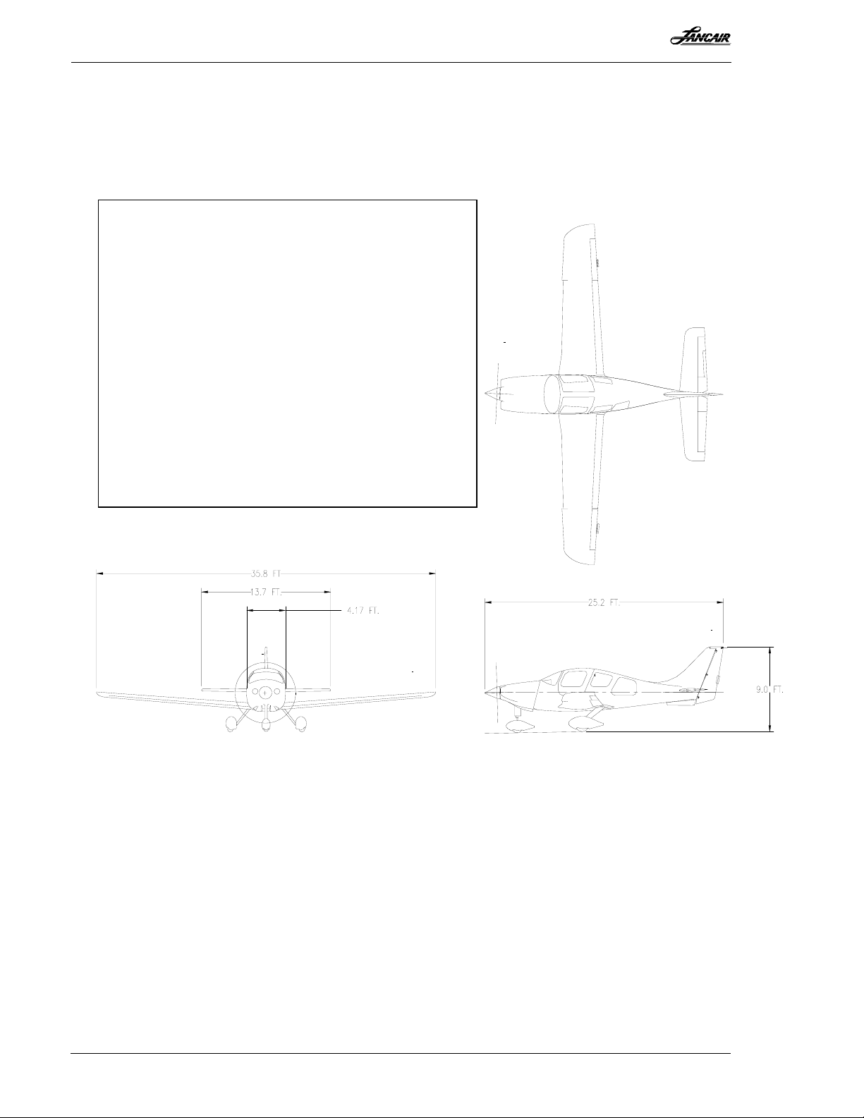
THREE-VIEW DRAWING OF THE AIRPLANE.................................................................... 1-2
INTRODUCTION ..................................................................................................................... 1-3
DESCRIPTIVE DATA .............................................................................................................. 1-4
Engine .................................................................................................................................. 1-4
Propeller ............................................................................................................................... 1-4
Fuel ...................................................................................................................................... 1-4
Oil ........................................................................................................................................ 1-4
Maximum Certificated Weights .......................................................................................... 1-5
Typical Airplane Weights .................................................................................................... 1-5
Cabin and Entry Dimensions ............................................................................................... 1-5
Space and Entry Dimensions of Baggage Compartment ..................................................... 1-5
Specific Loadings ................................................................................................................ 1-5
ABBREVIATIONS, TERMINOLOGY, AND SYMBOLS ..................................................... 1-6
Airspeed Terminology ......................................................................................................... 1-6
Meteorological Terminology ............................................................................................... 1-7
Engine Power and Controls Terminology ........................................................................... 1-8
Airplane Performance and Flight Planning Terminology ................................................... 1-9
Weight and Balance Terminology ..................................................................................... 1-10
REVISIONS AND CONVENTIONS USED IN THIS MANUAL ........................................ 1-11
Supplements ....................................................................................................................... 1-12
Use of the terms Warning, Caution, and Note.................................................................... 1-12
Meaning of Shall, Will, Should, and May .......................................................................... 1-12
Meaning of Land as Soon as Possible or Practicable ....................................................... 1-12
CONVERSION CHARTS ....................................................................................................... 1-12
Kilograms and Pounds ....................................................................................................... 1-13
Feet and Meters .................................................................................................................. 1-14
Inches and Centimeters....................................................................................................... 1-15
Knots, Statute Miles, and Kilometers................................................................................. 1-16
Liters, Imperial Gallons, and U.S. Gallons ........................................................................ 1-17
Temperature Relationship (Fahrenheit and Celsius) .......................................................... 1-20
Fuel Weights and Conversion Relationships ..................................................................... 1-21

Section 1
General Columbia 400 (LC41-550FG)
RC050002 Initial Issue of Manual: November 10, 2004
1-2 Latest Revision Level/Date: -/11-10-2004
THREE-VIEW DRAWING OF THE AIRPLANE
Figure 1 - 1
SPECIFICATIONS
Wing Area 141.2 ft.2(13.1 m2)
Wing Span 35.8 ft. (10.9 m)
Length 25.2 ft. (7.68 m)
Empty Weight (±) 2500 lbs. (1134 kg)
Gross Weight 3600 lbs. (1633 kg)
Stall Speed 59 KIAS 60 KCAS
Maneuvering Speed 158 KIAS 162 KCAS
Cruising Speed 181 KIAS 185 KCAS
Never Exceed Speed 230 KIAS 235 KCAS
Engine 310 HP Continental
TSIO-550-C
Propeller Hartzell
78 in. (198 cm) Constant Speed
Governor McCauley
*Note: Wingspan is 36 ft.± with position lights.

Section 1
Columbia 400 (LC41-550FG) General
Initial Issue of Manual: November 10, 2004 RC050002
Latest Revision Level/Date: -/11-10-2004 1-3
Section 1
General
INTRODUCTION
This handbook is written in nine sections and includes the material required to be furnished to
the pilot by Federal Aviation Regulations and additional information provided by the manufac-
turer and constitutes the FAA Approved Airplane Flight Manual. Section 1 contains generalized
descriptive data about the airplane including dimensions, fuel and oil capacities, and certificated
weights. There are also definitions and explanations of symbols, abbreviations, and commonly
used terminology for this airplane. Finally, conventions specific to this manual are detailed.
NOTE
Federal Aviation Regulations require that a current Handbook be in the
airplane during flight. It is the operator’s responsibility to maintain the
Handbook in a current status. The manufacturer provides the registered
owner(s) of the airplane with revisions.
In countries other than the United States, FAA operating rules may not
apply. Operators must ensure that the aircraft is operated in accordance
with national operating rules.

Section 1
General Columbia 400 (LC41-550FG)
RC050002 Initial Issue of Manual: November 10, 2004
1-4 Latest Revision Level/Date: -/11-10-2004
DESCRIPTIVE DATA
ENGINE
Number of Engines: 1
Engine Manufacturer: Teledyne Continental
Engine Model Number: TSIO-550-C
Engine Type: Twin-turbocharged, direct drive, air-cooled, horizontally opposed, fuel-injected,
six-cylinder engine with 552 in.3 (9.0 L) displacement
Takeoff Power: 310 BHP at 2600 RPM , 35.5 in of Hg
Maximum Continuous Power: 310 BHP at 2600 RPM
Maximum Normal Operating Power: 262 BHP (85%) at 2500 RPM, and 33.5 in of Hg
Maximum Climb Power: 310 BHP at 2600 RPM
Maximum Cruise Power: 262 BHP at 2550 RPM
PROPELLER
Propeller Manufacturer: Hartzell
Propeller Hub and Blade Model Number: HC-H3YF-1RF and F7693DF
Number of Blades: 3
Propeller Diameter: 77 in. (196 cm) minimum, 78 in. (198 cm) maximum
Propeller Type: Constant speed and hydraulically actuated, with a low pitch setting of 16.5o±
0.2° and a high pitch setting of 42.0o± 1.0° (30 inch station)
FUEL
The following fuel grades, including the respective colors, are approved for this airplane.
100LL Grade Aviation Fuel (Blue)
100 Grade Aviation Fuel (Green)
Total Fuel Capacity - 106 Gallons (401 L)
Total Capacity Each Tank: 53 Gallons (201 L)
Total Usable Fuel: 49 Gallons (186 L)/tank, 98 Gallons (371 L) Total
NOTE
Under certain atmospheric conditions, ice can form along various segments
of the fuel system. Under these conditions, isopropyl alcohol, ethylene glycol
monomethyl ether, or diethylene glycol monomethyl ether may be added to
the fuel supply. Additive concentrations shall not exceed 3% for isopropyl
alcohol or 0.15% for ethylene glycol monomethyl ether and diethylene glycol
monomethyl ether (military specification MIL-I-27686E). See Figure 8 - 1 in
Section 8 for a chart of fuel additive mixing ratios.
OIL
Specification or Oil Grade (the first 25 engine hours) – Non-dispersant mineral oil
conforming to SAE J1966 shall be used during the first 25 hours of flight operations. However, if
the engine is flown less than once a week, a straight mineral oil with corrosion preventative
MIL-C-6529 for the first 25 hours is recommended.
Specification or Oil Grade (after 25 engine hours) – Teledyne Continental Motors
Specification MHS-24. An ashless dispersant oil shall be used after 25 hours.

Section 1
Columbia 400 (LC41-550FG) General
Initial Issue of Manual: November 10, 2004 RC050002
Latest Revision Level/Date: -/11-10-2004 1-5
Viscosity Recommended for Various Average Air Temperature Ranges
Below 40°F (4°C) SAE 30, 10W30, 15W50, or 20W50
Above 40°F (4°C) SAE 50, 15W50, or 20W50
Total Oil Capacity
Sump: 8 Quarts (7.6 L)
Total: 10 Quarts (9.5 L)
Drain and Refill Quantity: 8 Quarts (7.6 L)
Oil Quantity Operating Range: 6 to 8 Quarts (5.7 to 7.6 L)
NOTE
The first time the airplane is filled with oil, additional oil is required for the
filter, oil cooler, and propeller dome. At subsequent oil changes, this
additional oil is not drainable from the system, and the added oil is mixed
with a few quarts of older oil in the oil system.
MAXIMUM CERTIFICATED WEIGHTS
Ramp Weight: 3600 lbs. (1633 kg)
Takeoff Weight: 3600 lbs. (1633 kg)
Landing Weight: 3420 lbs. (1551 kg)
Baggage Weight: 120 lbs. (54.4 kg)
TYPICAL AIRPLANE WEIGHTS
The empty weight of a typical airplane offered with four-place seating, standard interior,
avionics, accessories, and equipment has a standard empty weight of about 2500 lbs. (1134 kg).
Maximum Useful Load: 1100 lbs.* (499 kg)
*(The useful load varies for each airplane. Please see Section 6 for specific details.)
CABIN AND ENTRY DIMENSIONS
Maximum Cabin Width: 48.17 inches (122 cm)
Maximum Cabin Length (Firewall to aft limit of baggage compartment):
139.6 inches (354.6 cm)
Maximum Cabin Height: 49 inches (124.5 cm)
Minimum Entry Width: 33 inches (83.8 cm)
Minimum Entry Height: 33 inches (83.8 cm)
Maximum Entry Clearance: 46 inches (116.8 cm)
SPACE AND ENTRY DIMENSIONS OF BAGGAGE COMPARTMENT
Maximum Baggage Compartment Width: 38.5 inches (97.8 cm)
Maximum Baggage Compartment Length: 52 inches (132 cm) (Including Shelf)
Maximum Baggage Compartment Height: 34.5 inches (87.6 cm)
Maximum Baggage Entry Width: 28 inches (71.1 cm) (Diagonal Measurement)
SPECIFIC LOADINGS
Wing Loading: 25.50 lbs./sq. ft
Power Loading: 11.61 lbs./hp

Section 1
General Columbia 400 (LC41-550FG)
RC050002 Initial Issue of Manual: November 10, 2004
1-6 Latest Revision Level/Date: -/11-10-2004
ABBREVIATIONS, TERMINOLOGY, AND SYMBOLS
AIRSPEED TERMINOLOGY
CAS Calibrated Airspeed means the indicated speed of an
aircraft, corrected for position and instrument error.
Calibrated airspeed is equal to true airspeed in standar
d
atmosphere at sea level.
KCAS Calibrated Airspeed expressed in knots.
GS Ground Speed is the speed of an airplane relative to the
ground.
IAS Indicated Airspeed is the speed of an aircraft as shown on
the airspeed indicator when corrected for instrument error.
IAS values published in this Handbook assume zero
instrument error.
KIAS Indicated Airspeed expressed in knots.
TAS True Airspeed is the airspeed of an airplane relative to
undisturbed air, which is the CAS, corrected for altitude,
temperature and compressibility.
VHThis term refers to the maximum speed in level flight with
maximum continuous power.
VOThe maximum operating maneuvering speed of the
airplane. Do not apply full or abrupt control movements
above this speed. If a maneuver is entered gradually at VO
with maximum weight and full forward CG, the airplane
will stall at limit load. However, limit load can be exceede
d
at VOif abrupt control movements are used or the CG is
farther aft.
VFE Maximum Flap Extended Speed is the highest spee
d
permissible with wing flaps in a prescribed extende
d
position.
VNE Never Exceed Speed is the speed limit that may not be
exceeded at any time.
VNO Maximum Structural Cruising Speed is the speed that must
not be exceeded except in smooth air and then only with
caution.

Section 1
Columbia 400 (LC41-550FG) General
Initial Issue of Manual: November 10, 2004 RC050002
Latest Revision Level/Date: -/11-10-2004 1-7
VSStalling Speed or the minimum steady flight speed at which
the airplane is controllable.
VSO Stalling Speed or the minimum steady flight speed at which
the airplane is controllable in the landing configuration.
VXBest Angle-of-Climb Speed is the airspeed that delivers the
greatest gain of altitude in the shortest possible horizontal
distance.
VYBest Rate-of-Climb Speed is the airspeed that delivers the
greatest gain in altitude in the shortest possible time.
METEOROLOGICAL TERMINOLOGY
ISA International Standard Atmosphere in which:
1. The air is a dry perfect gas;
2. The temperature at sea level (SL) is 15°C (59°F);
3. The pressure at SL is 29.92 inches of Hg (1013.2 mb);
4. The temperature gradient from SL to an altitude where
the temperature is -56.5°C (-69.7°F) is -0.00198°C
(-.003564°F) per foot, and zero above that altitude.
Standard Temperature Standard Temperature is 15°C (59ºF) at sea level pressure
altitude and decreases 2°C (3.2°F) for each 1000 feet o
f
altitude.
OAT Outside Air Temperature is the free air static temperature
obtained either from in-flight temperature indications o
r
ground meteorological sources, adjusted for instrument
error and compressibility effects.
Indicated Pressure Altitude The number actually read from an altimeter when the
barometric subscale has been set to 29.92 inches of Hg
(1013.2 mb).
Pressure Altitude (PA) Altitude measured from standard sea level pressure (29.92
inches of Hg) by a pressure or barometric altimeter. It is the
indicated pressure altitude corrected for position an
d
instrument error. In this Handbook, altimeter instrument
errors are assumed to be zero.
Station Pressure Actual atmospheric pressure at field elevation.

Section 1
General Columbia 400 (LC41-550FG)
RC050002 Initial Issue of Manual: November 10, 2004
1-8 Latest Revision Level/Date: -/11-10-2004
Wind The wind velocities recorded as variables on the charts o
f
this handbook are to be understood as the headwind o
r
tailwind components of the reported winds.
ENGINE POWER & CONTROLS TERMINOLOGY
BHP Brake Horsepower is the power developed by the engine.
MP Manifold Pressure is the pressure measured in the intake
system of the engine and is depicted as inches of Hg.
MCP Maximum Continuous Power is the maximum power fo
r
abnormal or emergency operations.
Maximum Cruise Power The maximum power recommended for cruise.
MNOP Maximum Normal Operating Power is the maximu
m
power for all normal operations (except takeoff). This
power, in most situations, is the same as Maximum Contin-
uous Power.
Mixture Control The Mixture Control provides a mechanical linkage with
the fuel control unit of fuel injection engines, to control the
size of the fuel feed aperture, and thus, the air/fuel mixture.
It is also a primary means to shut down the engine.
Propeller Control The lever used to select a propeller speed.
Propeller Governor The device that regulates the RPM of the engine an
d
propeller by increasing or decreasing the propeller pitch,
through a pitch change mechanism in the propeller hub.
RPM Revolutions Per Minute is a measure of engine and/o
r
propeller speed.
Stall Strip Small triangular strips installed along the leading edge o
f
an airplane wing to disrupt the airflow at high angles o
f
attack in a controlled way. The strips improve stall
characteristics and spin recovery.
Tachometer An instrument that indicates propeller rotation and is
expressed as revolutions per minute (RPM).
Throttle The lever used to control engine power, from the lowest
through the highest power, by controlling propeller pitch,
fuel flow, engine speed, or any combination of these.

Section 1
Columbia 400 (LC41-550FG) General
Initial Issue of Manual: November 10, 2004 RC050002
Latest Revision Level/Date: -/11-10-2004 1-9
TIT Gauge The Turbine Inlet Temperature indicator is the instrument
used to identify the lean fuel flow mixtures for various
power settings.
Wing Cuff Specially shaped composite construction on the outboar
d
leading edge of the wing. The cuff increases the camber o
f
the airfoil and improves the slow-flight and stall
characteristics of the wing.
AIRPLANE PERFORMANCE & FLIGHT PLANNING TERMINOLOGY
Demonstrated Crosswind
Velocity
Demonstrated Crosswind Velocity is the velocity of the
crosswind component for which adequate control of the
airplane can be maintained during takeoff and landing. The
value shown is not considered limiting.
G A unit of acceleration equal to the acceleration of gravity at
the surface of the earth. The term is frequently used to
quantify additional forces exerted on the airplane and is
expressed as multiples of the basic gravitational force, e.g.,
a 1.7-g force.
GPH Gallons Per Hour is the quantity of fuel consumed in an
hour expressed in gallons.
Limit Load The maximum load a structure is designed to carry and the
factor of safety, is the percentage of limit load the structure
can actually carry before its ultimate load is reached. A
structure designed to carry a load of 1,000 pounds with a
safety factor of 1.5 has an ultimate load of 1,500 pounds.
The airplane can be damaged above limit load.
NMPG Nautical Miles per Gallon is the distance (in nautical
miles) which can be expected per gallon of fuel consume
d
at a specific power setting and/or flight configuration.
PPH Pounds Per Hour is the quantity of fuel consumed in an
hour expressed in pounds.
Unusable Fuel Unusable Fuel is the amount of fuel expressed in gallons
that cannot safely be used in flight. Unusable Fuel is the
fuel remaining after a runout test has been completed in
accordance with governmental regulations.
Ultimate Load The amount of load that can be applied to an aircraft
structure before it fails. The airplane can be damage
d
between limit and ultimate load, and it can fail
catastrophically above ultimate load.

Section 1
General Columbia 400 (LC41-550FG)
RC050002 Initial Issue of Manual: November 10, 2004
1-10 Latest Revision Level/Date: -/11-10-2004
Usable Fuel Usable Fuel is the quantity available that can safely be
used for flight planning purposes.
WEIGHT AND BALANCE
Arm The Arm is the horizontal distance from the reference
datum to the center of gravity (C.G.) of an item.
Basic Empty Weight The Basic Empty Weight is the Standard Empty Weight
plus optional equipment.
CG The Center of Gravity is the point at which the airplane
will
b
alance if suspended. Its distance from the datum is
found by dividing the total moment by the total weight o
f
the airplane.
CG Arm The arm obtained by adding the individual moments of the
airplane and dividing the sum by the total weight.
CG Limits The extreme center of gravity locations within which the
airplane must be operated at a given weight.
Maximum Empty Weight This is the maximum allowable weight of the airplane
when empty, before fuel, passengers, and baggage are
added. Subtracting the minimum useful load from the
maximum gross weight produces the maximum empty
weight. The amount of additional equipment that can be
added to the airplane is determined by subtracting the
standard empty weight from the maximum empty weight.
See page 6-15 for an example.
Maximum Gross Weight The maximum loaded weight of an aircraft. Gross weight
includes the total weight of the aircraft, the weight of the
fuel and oil, and the weight of all the load it is carrying.
Maximum Landing Weight The maximum weight approved for landing touchdown.
Maximum Ramp Weight The maximum weight approved for ground maneuver. (It
includes the weight of the fuel used for startup, taxi, an
d
runup.)
Maximum Takeoff Weight The maximum weight approved for the start of the takeof
f
run.

Section 1
Columbia 400 (LC41-550FG) General
Initial Issue of Manual: November 10, 2004 RC050002
Latest Revision Level/Date: -/11-10-2004 1-11
Maximum Zero-Fuel Weight The maximum weight authorized for an aircraft that does not
include the weight of the fuel. This weight includes the basic
empty weight plus the weight of the passengers and baggage.
The maximum zero-fuel weight can change depending on the
center of gravity location. See Figure 2 - 4 for an example.
Minimum Flight Weight This is the minimum weight permitted for flight operations
and includes the basic empty weight plus fuel, pilot,
passengers, and baggage. The minimum flight weight can
change depending on the center of gravity location. See
Figure 2 - 4 for an example.
Minimum Useful Load For utility category airplanes, certified for night or IF
R
operations, a weight of 190 pounds for each installed seat
plus the fuel weight for 45 minutes at maximum continuous
power.
Moment The moment of a lever is the distance, in inches, between the
point at which a force is applied and the fulcrum, or the point
about which a lever rotates, multiplied by the force, in
pounds. Moment is expressed in inch-pounds.
Reference Datum This is an imaginary vertical plane from which all horizontal
distances are measured for balance purposes.
Standard Empty Weight This is the weight of a standard airplane including unusable
fuel, full operating fluids, and full oil.
Station The Station is a location along the airplane's fuselage usually
given in terms of distance from the reference datum, i.e.,
Station 40 would be 40 inches from the reference datum.
Useful Load The Useful Load is the difference between Takeoff Weight o
r
Ramp Weight, if applicable, and Basic Empty Weight.
MISCELLANEOUS
Flight Time - Airplanes
Pilot time that commences when an aircraft moves under its
own power for the purpose of flight and ends when the
aircraft comes to rest after landing.
Time in Service Time in service, with respect to maintenance time records,
means the time from the moment an aircraft leaves the
surface of the earth until it touches it at the next point o
f
landing.

Section 1
General Columbia 400 (LC41-550FG)
RC050002 Initial Issue of Manual: November 10, 2004
1-12 Latest Revision Level/Date: -/11-10-2004
SUPPLEMENTS
Equipment, which is not covered in Sections 1 through 8 of the Information Manual, is included
in Section 9, as applicable.
USE OF THE TERMS WARNING, CAUTION, AND NOTE
The following conventions will be used for the terms, Warning,Caution, and Note.
WARNING
The use of a Warning symbol means that information which follows is of
critical importance and concerns procedures and techniques which could
cause or result in personal injury or death if not carefully followed.
CAUTION
The use of a Caution symbol means that information which follows is of
significant importance and concerns procedures and techniques which could
cause or result in damage to the airplane and/or its equipment if not
carefully followed.
NOTE
The use of the term “NOTE” means the information that follows is essential
to emphasize.
MEANING OF SHALL, WILL, SHOULD, AND MAY
The words shall and will are used to denote a mandatory requirement. The word should denotes
something that is recommended but not mandatory. The word may is permissive in nature and
suggests something that is optional.
MEANING OF LAND AS SOON AS POSSIBLE OR PRACTICABLE
The use of these two terms relates to the urgency of the situation. When it is suggested to land as
soon as possible, this means to land at the nearest suitable airfield after considering weather
conditions, ambient lighting, approach facilities, and landing requirements. When it is suggested
to land as soon as practicable, this means that the flight may be continued to an airport with
superior facilities, including maintenance support, and weather conditions.
CONVERSION CHARTS
On the following pages are a series of charts and graphs for conversion to and from U.S. weights
and measures to metric and imperial equivalents. The charts and graphs are included to help
pilots who live in countries other than the United States or pilots from the United States who are
traveling to or within other countries.

Section 1
Columbia 400 (LC41-550FG) General
Initial Issue of Manual: November 10, 2004 RC050002
Latest Revision Level/Date: -/11-10-2004 1-13
KILOGRAMS AND POUNDS
CONVERTING KILOGRAMS TO POUNDS
Kilograms 0 1 2 3 4 5 6 7 8 9
0 2.205 4.409 6.614 8.818 11.023 13.228 15.432 17.637 19.842
10 22.046 24.251 26.455 28.660 30.865 33.069 35.274 37.479 39.683 41.888
20 44.092 46.297 48.502 50.706 52.911 55.116 57.320 59.525 61.729 63.934
30 66.139 68.343 70.548 72.753 74.957 77.162 79.366 81.571 83.776 85.980
40 88.185 90.390 92.594 94.799 97.003 99.208 101.413 103.617 105.822 108.026
50 110.231 112.436 114.640 116.845 119.050 121.254 123.459 125.663 127.868 130.073
60 132.277 134.482 136.687 138.891 141.096 143.300 145.505 147.710 149.914 152.119
70 154.324 156.528 158.733 160.937 163.142 165.347 167.551 169.756 171.961 174.165
80 176.370 178.574 180.779 182.984 185.188 187.393 189.597 191.802 194.007 196.211
90 198.416 200.621 202.825 205.030 207.234 209.439 211.644 213.848 216.053 218.258
100 220.462 222.667 224.871 227.076 229.281 231.485 233.690 235.895 238.099 240.304
Example: Convert 76 kilograms to pounds. Locate the 70 row in the first column and then move right, horizontally
to Column No. 6 and read the solution, 167.551 pounds.
Figure 1 - 2
CONVERTING POUNDS TO KILOGRAMS
Pounds 0 1 2 3 4 5 6 7 8 9
0 0.454 0.907 1.361 1.814 2.268 2.722 3.175 3.629 4.082
10 4.536 4.990 5.443 5.897 6.350 6.804 7.257 7.711 8.165 8.618
20 9.072 9.525 9.979 10.433 10.886 11.340 11.793 12.247 12.701 13.154
30 13.608 14.061 14.515 14.969 15.422 15.876 16.329 16.783 17.236 17.690
40 18.144 18.597 19.051 19.504 19.958 20.412 20.865 21.319 21.772 22.226
50 22.680 23.133 23.587 24.040 24.494 24.948 25.401 25.855 26.308 26.762
60 27.216 27.669 28.123 28.576 29.030 29.483 29.937 30.391 30.844 31.298
70 31.751 32.205 32.659 33.112 33.566 34.019 34.473 34.927 35.380 35.834
80 36.287 36.741 37.195 37.648 38.102 38.555 39.009 39.463 39.916 40.370
90 40.823 41.277 41.730 42.184 42.638 43.091 43.545 43.998 44.452 44.906
100 45.359 45.813 46.266 46.720 47.174 47.627 48.081 48.534 48.988 49.442
Example: Convert 40 pounds to kilograms. Locate the 40 row in the first column and then move right one column to
Column No. 0 and read the solution, 18.144 kilograms.
Figure 1 - 3

Section 1
General Columbia 400 (LC41-550FG)
RC050002 Initial Issue of Manual: November 10, 2004
1-14 Latest Revision Level/Date: -/11-10-2004
FEET AND METERS
CONVERTING METERS TO FEET
Meters 0 1 2 3 4 5 6 7 8 9
0 3.281 6.562 9.843 13.123 16.404 19.685 22.966 26.247 29.528
10 32.808 36.089 39.370 42.651 45.932 49.213 52.493 55.774 59.055 62.336
20 65.617 68.898 72.178 75.459 78.740 82.021 85.302 88.583 91.864 95.144
30 98.425 101.706 104.987 108.268 111.549 114.829 118.110 121.391 124.672 127.953
40 131.234 134.514 137.795 141.076 144.357 147.638 150.919 154.199 157.480 160.761
50 164.042 167.323 170.604 173.885 177.165 180.446 183.727 187.008 190.289 193.570
60 196.850 200.131 203.412 206.693 209.974 213.255 216.535 219.816 223.097 226.378
70 229.659 232.940 236.220 239.501 242.782 246.063 249.344 252.625 255.906 259.186
80 262.467 265.748 269.029 272.310 275.591 278.871 282.152 285.433 288.714 291.995
90 295.276 298.556 301.837 305.118 308.399 311.680 314.961 318.241 321.522 324.803
100 328.084 331.365 334.646 337.927 341.207 344.488 347.769 351.050 354.331 357.612
Example: Refer to Figure 1-2 and Figure 1-3 for examples of how to use these types of tables.
Figure 1 - 4
CONVERTING FEET TO METERS
Feet 0 1 2 3 4 5 6 7 8 9
0 0.305 0.610 0.914 1.219 1.524 1.829 2.134 2.438 2.743
10 3.048 3.353 3.658 3.962 4.267 4.572 4.877 5.182 5.486 5.791
20 6.096 6.401 6.706 7.010 7.315 7.620 7.925 8.230 8.534 8.839
30 9.144 9.449 9.754 10.058 10.363 10.668 10.973 11.278 11.582 11.887
40 12.192 12.497 12.802 13.106 13.411 13.716 14.021 14.326 14.630 14.935
50 15.240 15.545 15.850 16.154 16.459 16.764 17.069 17.374 17.678 17.983
60 18.288 18.593 18.898 19.202 19.507 19.812 20.117 20.422 20.726 21.031
70 21.336 21.641 21.946 22.250 22.555 22.860 23.165 23.470 23.774 24.079
80 24.384 24.689 24.994 25.298 25.603 25.908 26.213 26.518 26.822 27.127
90 27.432 27.737 28.042 28.346 28.651 28.956 29.261 29.566 29.870 30.175
100 30.480 30.785 31.090 31.394 31.699 32.004 32.309 32.614 32.918 33.223
Example: Refer to Figure 1-2 and Figure 1-3 for examples of how to use these types of tables.
Figure 1 - 5

Section 1
Columbia 400 (LC41-550FG) General
Initial Issue of Manual: November 10, 2004 RC050002
Latest Revision Level/Date: -/11-10-2004 1-15
INCHES AND CENTIMETERS
CONVERTING CENTIMETERS TO INCHES
Centimeters 0 1 2 3 4 5 6 7 8 9
0 0.394 0.787 1.181 1.575 1.969 2.362 2.756 3.150 3.543
10 3.937 4.331 4.724 5.118 5.512 5.906 6.299 6.693 7.087 7.480
20 7.874 8.268 8.661 9.055 9.449 9.843 10.236 10.630 11.024 11.417
30 11.811 12.205 12.598 12.992 13.386 13.780 14.173 14.567 14.961 15.354
40 15.748 16.142 16.535 16.929 17.323 17.717 18.110 18.504 18.898 19.291
50 19.685 20.079 20.472 20.866 21.260 21.654 22.047 22.441 22.835 23.228
60 23.622 24.016 24.409 24.803 25.197 25.591 25.984 26.378 26.772 27.165
70 27.559 27.953 28.346 28.740 29.134 29.528 29.921 30.315 30.709 31.102
80 31.496 31.890 32.283 32.677 33.071 33.465 33.858 34.252 34.646 35.039
90 35.433 35.827 36.220 36.614 37.008 37.402 37.795 38.189 38.583 38.976
100 39.370 39.764 40.157 40.551 40.945 41.339 41.732 42.126 42.520 42.913
Example: Refer to Figure 1-2 and Figure 1-3 for examples of how to use these types of tables.
Figure 1 - 6
CONVERTING INCHES TO CENTIMETERS
Inches 0 1 2 3 4 5 6 7 8 9
0 2.54 5.08 7.62 10.16 12.70 15.24 17.78 20.32 22.86
10 25.40 27.94 30.48 33.02 35.56 38.10 40.64 43.18 45.72 48.26
20 50.80 53.34 55.88 58.42 60.96 63.50 66.04 68.58 71.12 73.66
30 76.20 78.74 81.28 83.82 86.36 88.90 91.44 93.98 96.52 99.06
40 101.60 104.14 106.68 109.22 111.76 114.30 116.84 119.38 121.92 124.46
50 127.00 129.54 132.08 134.62 137.16 139.70 142.24 144.78 147.32 149.86
60 152.40 154.94 157.48 160.02 162.56 165.10 167.64 170.18 172.72 175.26
70 177.80 180.34 182.88 185.42 187.96 190.50 193.04 195.58 198.12 200.66
80 203.20 205.74 208.28 210.82 213.36 215.90 218.44 220.98 223.52 226.06
90 228.60 231.14 233.68 236.22 238.76 241.30 243.84 246.38 248.92 251.46
100 254.00 256.54 259.08 261.62 264.16 266.70 269.24 271.78 274.32 276.86
Example: Refer to Figure 1-2 and Figure 1-3 for examples of how to use these types of tables.
Figure 1 - 7

Section 1
General Columbia 400 (LC41-550FG)
RC050002 Initial Issue of Manual: November 10, 2004
1-16 Latest Revision Level/Date: -/11-10-2004
NAUTICAL MILES, STATUTE MILES, AND KILOMETERS
Nautical
Miles
Statute
Miles
Kilo-
meters
Nautical
Miles
Statute
Miles
Kilo-
meters
Nautical
Miles
Statute
Miles
Kilo-
meters
5 6 9 175 202 324 345 397 639
10 12 19 180 207 333 350 403 648
15 17 28 185 213 343 355 409 657
20 23 37 190 219 352 360 415 667
25 29 46 195 225 361 365 420 676
30 35 56 200 230 370 370 426 685
35 40 65 205 236 380 375 432 695
40 46 74 210 242 389 380 438 704
45 52 83 215 248 398 385 443 713
50 58 93 220 253 407 390 449 722
55 63 102 225 259 417 395 455 732
60 69 111 230 265 426 400 461 741
65 75 120 235 271 435 405 466 750
70 81 130 240 276 444 410 472 759
75 86 139 245 282 454 415 478 769
80 92 148 250 288 463 420 484 778
85 98 157 255 294 472 425 489 787
90 104 167 260 299 482 430 495 796
95 109 176 265 305 491 435 501 806
100 115 185 270 311 500 440 507 815
105 121 194 275 317 509 445 512 824
110 127 204 280 322 519 450 518 833
115 132 213 285 328 528 455 524 843
120 138 222 290 334 537 460 530 852
125 144 232 295 340 546 465 535 861
130 150 241 300 345 556 470 541 870
135 155 250 305 351 565 475 547 880
140 161 259 310 357 574 480 553 889
145 167 269 315 363 583 485 559 898
150 173 278 320 369 593 490 564 907
155 178 287 325 374 602 495 570 917
160 184 296 330 380 611 500 576 926
165 190 306 335 386 620 505 582 935
170 196 315 340 392 630 510 587 945
Figure 1 - 8
Table of contents
Other Lancair Aircraft manuals
Popular Aircraft manuals by other brands

Piper
Piper COMANCHE Owner's handbook

Strong Enterprises
Strong Enterprises Para-Cushion 306 Squadron Seat owner's manual

Rolladen-Schneider
Rolladen-Schneider LS 4-a Flight manual

Bliss
Bliss BH-998 quick start guide

Van's Aircraft
Van's Aircraft RV 12iS Maintenance manual

3D Hobby Shop
3D Hobby Shop 59" AJ Slick installation manual