lancer Multi-Valve Unit Tower User manual

ABOUT THIS MANUAL
This booklet is an integral and essential part of the product and
should be handed over to the operator after the installation and
preserved for any further consultation that may be necessary.
Please read carefully the guidelines and warnings contained
herein as they are intended to provide the user with essential
information for the continued safe use and maintenance of the
product. In addition, it provides GUIDANCE ONLY to the user on
the correct services and site location of the unit.
BEFORE GETTING STARTED
Each unit is tested under operating conditions and is thoroughly
inspected before shipment. At the time of shipment, the carrier
accepts responsibility for the unit. Upon receiving the unit,
carefully inspect the carton for visible damage. If damage exists,
have the carrier note the damage on the freight bill and le a
claim with carrier. Responsibility for damage to the dispenser lies
with the carrier.
IMPORTANT SAFETY INSTRUCTIONS
The installation and relocation, if necessary, of this product must be carried out by qualied personnel with
up-to-date safety and hygiene knowledge and practical experience, in accordance with current regulations.
®
MVU
FOR QUALIFIED INSTALLER ONLY. This basic Installation Sheet is an initial release. If a complete Operations
Manual (for the unit being installed) is required or needed, please refer to the Lancer web site (lancercorp.com) for
immediate access, or for your convenience, scan this QR code with a mobile device (app required) for immediate
access to other Technical Documents and alternative translations (if available) pertaining to this unit. Contact Lancer
Customer Service for assistance as required.
The dispenser is for indoor use only. This unit is not a toy. Children should not be supervised not to play with appliance. It should
not be used by children or inrm persons without supervision. This appliance is not intended for use by persons (including children)
with reduced physical, sensory or mental capabilities, or lack of experience and knowledge, unless they have been given
supervision or instruction concerning use of the appliance by a person responsible for their safety. Cleaning and user maintenance
shall not be performed by children without supervision. The min/max ambient operating temperature for the dispenser is 40°F to
90°F (4°C to 32°C). Do not operate unit below minimum ambient operation conditions. Should freezing occur, cease operation of
the unit and contact authorized service technician. Service, cleaning and sanitizing should be accomplished only by trained
personnel. Applicable safety precautions must be observed. Instruction warnings on the product being used must be followed.
! Intended Use
Multi-Valve Unit (MVU) Tower
LANCER INSTALLATION/OPERATION MANUAL
LANCER PN: 28-2826/02
Revision: May 2018

2
• WARNING: Carbon Dioxide (CO2) is a colorless, noncombustible gas with a light pungent odor. High percentages of CO2may
displace oxygen in the blood.
• WARNING: Prolonged exposure to CO2can be harmful. Personnel exposed to high concentrations of CO2gas will experience
tremors which are followed by a loss of consciousness and suocation.
• WARNING: If a CO2gas leak is suspected, immediately ventilate the contaminated area before attempting to repair the leak.
• WARNING: Strict attention must be observed in the prevention of CO2gas leaks in the entire CO2and soft drink system.
5 Carbon Dioxide (CO2)
Provide an adequate potable water supply. Water pipe connections and xtures directly connected to a potable water supply must
be sized, installed, and maintained according to federal, state, and local laws. The water supply line must be at least a 3/8 inches
(9.525 mm) pipe with a minimum of 25 PSI (0.172 MPA) line pressure, but not exceeding a maximum of 65 PSI (0.448 MPA).
Water pressure exceeding 65 PSI (0.448 MPA) must be reduced to 65 PSI (0.448 MPA) with the provided pressure regulator. Use
a lter in the water line to avoid equipment damage and beverage o-taste. Check the water lter periodically, as required by local
conditions. The water supply must be protected by means of an air gap, a backow prevention device or another approved method
to comply with NSF standards. A leaking inlet water check valve will allow carbonated water to ow back through the pump when it
is shut o and contaminate the water supply. Ensure the backow prevention device complies with ASSE and local
standards. It is the responsibility of the installer to ensure compliance.
! Water Notice
SPECIFICATIONS & FEATURES
DIMENSIONS
Width: 7.25 inches (184.15 mm)
Depth: 9 inches (228.6 mm)
Height: 16.5 inches (419 mm)
WEIGHT
Shipping: 15 lbs (7.0 kg)
CARBON DIOXIDE (CO2) SUPPLY
Min Pressure: 70 PSIG (0.483 MPA)
Max Pressure: 80 PSIG (0.552 MPA)
FITTINGS
Plain/Carb Water Inlet: 3/8 inch barb
Brand Syrup Inlets: 3/8 inch barb
ELECTRICAL
115 VAC / 60 Hz
PLAIN/CARBONATED WATER SUPPLY
Min Flowing Pressure: 25 PSI (0.172 MPA)
Max Static Pressure: 65 PSI (0.448 MPA)
This unit emits a sound pressure level below 70 dB
Check the dispenser name plate label, located behind the splash plate, for the correct electrical requirements of unit. Do not plug
into a wall electrical outlet unless the current shown on the serial number plate agrees with local current available. Follow all local
electrical codes when making connections. Each dispenser must have a separate electrical circuit. Do not use extension cords with
this unit. Do not ‘gang’ together with other electrical devices on the same outlet. The keyswitch does not disable the line voltage to
the transformer primary. Always disconnect electrical power to the unit to prevent personal injury before attempting any internal
maintenance. The resettable breaker switch should not be used as a substitute for unplugging the dispenser from the power source
to service the unit. Only qualied personnel should service internal components of electrical control housing. Make sure that all
water lines are tight and units are dry before making any electrical connections!
F Electrical Warning
Your Service Agent:
Service Agent Telephone Number:
Serial Number:
Model Number:
This manual was developed by the Lancer Corporation as a reference for the owner/operator and installer of this
dispenser. Please read this guide before installation and operation of this dispenser. If service is required please call your
Lancer Service Agent or Lancer Customer Service. Always have your model and serial number available when you call.
READ THIS MANUAL

3
INSTALLATION
Unpack the Dispenser
1. The Lancer dispenser is shipped in a corrugated shipping
carton.
2. Remove dispenser from corrugated shipping carton.
Tower Installation
1. Route appropriate tubing from the water source to the plain
water inlet at tower and connect tubing to inlet using the
oetiker pliers and ttings,(see Plumbing Diagram on unit or
page 11 for reference).
Inspect unit for concealed damage. If evident, notify
deliveringcarrierandleaclaimagainstthesame.
NOTE
Selecting/Preparing Counter Location
1. Select a level, well ventilated location that is in close
proximity to a properly grounded electrical outlet, within ve
(5) feet (1.5 m) of a drain, a water supply that meets the
requirements shown in the Specications section found on
page 2, and away from direct sunlight or overhead lighting.
2. The dispenser is designed to be installed permanently to
a counter and must be sealed with a bead of clear silicone
caulk or sealant which provides a smooth and easily
cleanable bond to the counter.
The dispenser should only be installed in a location
where it can be overseen by trained personnel
NOTE
NSF listed units must be sealed to the counter or have
four (4) inch legs installed.
NOTE
To assure that beverage service is accessible to all
customers, Lancer recommends that counter height
and equipment selection be planned carefully. The
2010 ADA Standards for Accessible Design states that
themaximumreachheightfromtheoorshouldbeno
more than 48” if touch point is less than 10” from the
front of the counter, or a maximum of 46” if the touch
point is more than 10” and less than 27” from the front
of the counter. For more information about the
customer’s legal requirements for the accessibility of
installed equipment, refer to 2010 ADA Standards for
Accessible Design - http://www.ada.gov.
NOTE
In order to facilitate proper dispenser drainage, ensure
that the dispenser is level, front to back and side to
side. Place a level on the top of the rear edge of the
dispenser. The bubble must settle between the level
lines. Repeat this procedure for the remaining three
sides. Level unit if necessary. For optimum perfor-
mance place the unit at a 0° tilt. The maximum tilt is 5°.
Leveling the Dispenser:
3. Select a location for the remote chiller systerm, syrup
pumps, CO2 tank, syrup containers, and water lter
(recommended).
4. Cut out required opening in counter for the water/soda and
syrup lines in the designated dispenser location.
Unit is designed to be supported by a remote chiller
system or remote ice cooled system. Please see the
manufacturer’sspecicationsandinstructionsfor
installation.
NOTE
6. Connect drain line to tting at the bottom of the drip tray and
route to designated open type foor drain.
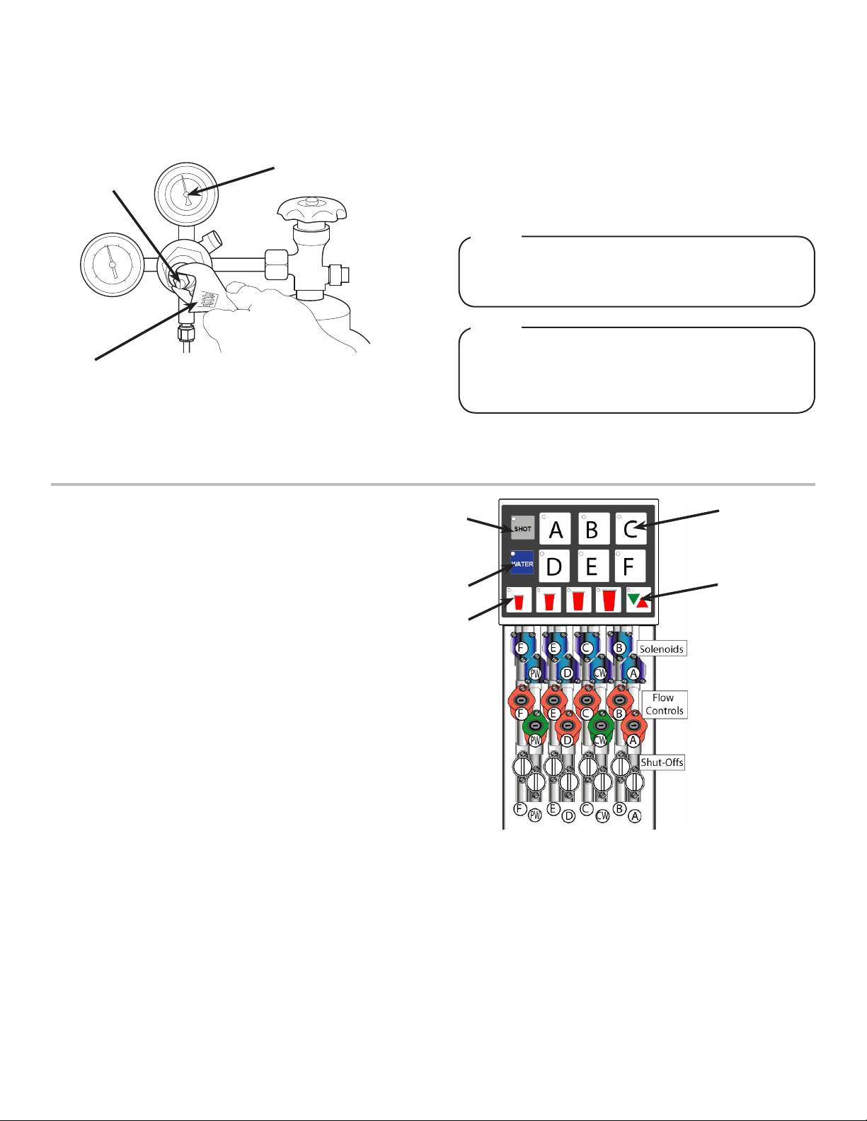
A
B
C
A. Oetiker Pliers
B. Fitting
C. Tubing
D. Syrup/Water
Inlet
D
DO NOT PLUG UNIT INTO GROUNDED ELECTRICAL
OUTLET AT THIS TIME. Make sure that all water lines
are tight and unit is dry before making any electrical
connections
! WARNING
4. Route appropriate tubing from the syrup pump location to the
syrup inlets and connect tubing to inlet. Repeat for remaining
syrup lines
5. Route the power supply cord to a grounded electrical outlet
of the proper voltage and amperage rating.
Drain line must be insulated with a closed cell
insulation. Insulation must cover the entire length of
thedrainhose,includingttings.Thedrainshouldbe
installed in such a manner that water does not collect
in sags or other low points, as condensation will form.
! CAUTION
Pouring hot water down the drain may cause the Drain
Tube to collapse. Allow only luke warm or cold water to
enter the Drain Tube. Pouringcoee,tea,orother
similar substances down the drain may cause the Drain
Tube to become clogged.
! ATTENTION
2. Connect tubing to water source then ush water line to check
for leaks.
3. Route appropriate tubing from the remote chiller system
location to the carbonated water inlet on tower and connect
tubing to inlet.

4
Installing CO2Supply
1. Connect high pressure CO2regulator assembly to CO2
cylinder or bulk system.
- Thread regulator nut on to tank, then
tighten nut with wrench
A. CO2Regulator
B. Outlet
C. Wrench
D. CO2 Supply
A
B
C
D
Before installing regulator, assure that a seal (washer
or o-ring) is present in regulator attachment nut.
! ATTENTION
2. Connect a 1/4” nut, stem and seal to CO2regulator outlet.
3. Route appropriate tubing from the low pressure CO2
regulator manifold location to the 1/4” nut, stem on the high
pressure CO2regulator attached to source and connect
tubing.
A dedicated CO2regulator is required to supply the CO2
inlet at the remote chiller as well as to all syrup pumps.
! ATTENTION
4. Route appropriate tubing from one of the low pressure CO2
regulator manifold outlets to the inlet at the remote chiller.
A
B
C
DA. Line to Dispenser
B. Line to Syrup Pumps
C. Line to CO2Regulator
D. CO2Regulator Manifold
6. Using a wrench, loosen lock nut on the regulator adjustment
screw of the high pressure CO2regulator connected to the
source, then using a screwdriver back out lock nut screw all
the way.
DO NOT TURN ON CO2SUPPLY AT THIS TIME
! WARNING
7. Repeat Step 6 for both low pressure CO2regulators on the
regulator manifold routed to the unit and the syrup pumps.
A. CO2Regulator
B. Screwdriver
C. Regulator Adjustment Screw
A
B
C
Dispenser Setup
1. Turn on water source.
2. Open the pressure relief valve located on the remote chiller
system or remote carbonator by ipping up on the valve cap
lever. Hold open until water ows from the relief valve then
close (ip down) reief valve.
3. Verify all Bag-In-Box contains syrup and check all
connections for leaks.
4. Connect tower and remote chiller power cords to grounded
electical outlet.
The dispenser must be properly electrically grounded
to avoid serious injury or fatal electrical shock. The
power cord has a three-prong grounded plug. If a
three-hole grounded electrical outlet is not available,
use an approved method to ground the unit. Follow all
local electrical codes when making connections. Each
dispenser must have a separate electrical circuit. Do
not use extension cords. Do not connect multiple
electrical devices on the same outlet.
! WARNING
A. CO2Regulator
B. 1/4” Nut, Stem & Seal
C. Line to CO2Regulator
Manifold
D. Oetiker Pliers
A
B
C
D
5. Route appropriate tubing from the second outlet of the low
pressure CO2regulator manifold to the syrup pumps
location.

5
A. Regulator Adjustment Screw
B. Adjust to 110 PSI (0.758 MPA)
C. Wrench
AB
C
8. Adjust both of the low pressure regulators on the regulator
manifold to 75 PSI (0.517 MPA) then tighten locknut with
wrench.
9. Activate each valve until gas-out.
10. Plug in the remote carbonator pump deck, if not already
done so, and turn the switch to the ON position.
11. Activate each valve until the carbonator pump comes on.
Release the button, allow carbonator to ll and stop.
Repeat this process until a steady ow of carbonated water
is achieved.
12. Activate each valve to purge air from the syrup lines.
The pump deck has a 3 minute timeout feature. If the
timeoutoccurs,turnthedeckOFFthenONbyipping
the switch on the control box.
NOTE
To check for CO2leaks, close the valve on the CO2
cylinder and observe if the pressure to the system
dropswiththecylindervalveclosedforveminutes.
Open the cylinder valve after check.
NOTE
5. Activate each valve to ensure a good ow of water is
achieved.
6. Ensure pump deck is turned OFF before turning on CO2.
7. Turn on CO2at the source then, using a screwdriver, adjust
the high pressure regulator at the source to 110 PSI (0.758
MPA) then tighten locknut with wrench.
MULTI-VALVE UNIT (MVU) PROGRAMMING
Overview
The MVU module is designed to dispense up to 6 beverages and/
or shots through one dispense nozzle. The MVU consists of: an
electronic board, touch pad which is used to both program and
dispense drinks, 8 solenoids (one for each circuit), 8 ow controls
(one for each circuit), and 8 shut-os
1. Positions A and D are plumbed through the cold plate
meaning that the syrup is chilled in each of those locations.
2. Positions B, C, E, and F bypass the cold plate so the syrups
are not chilled and should NOT be used for carbonated
beverages.
3. The water ow controls are green in color the plain water
control is labeled with “PW”, and the carbonated water is
labeled with “CW”. There are no stickers on the water ow
controls.
4. The syrup ow control modules are red and correspond to
the touch pad, (touchpad position A activates solenoid A).
5. The 8 solenoids are 24 VDC, activated by the touch pad, and
controlled by the MVU circuit board.
A. Brand Button
B. Shot Button
C. Water Button
D. Portion Control
Buttons
E. Pour/Cancel
A
E
B
C
D

6
Set MVU for Carb, Non-Carb, or Flavor Shot Only
Refer to Overview Illustration for touch pad reference.
NOTE
The Pour/Cancel LED will illuminate and the Shot
button LED will blink one time, once in programming
mode.
NOTE
The Program will save automatically in 60 seconds if
no additional changes are made in that time frame;
however, you can exit any time within the 60 second
window by pressing Pour/Cancel. The changes you’ve
made will be saved.
NOTE
1. On the MVU panel, press and hold both of the A and C brand
buttons at the same time to enter programming mode.
2. Observe brand LED’s to identify the water setting for each
button:
• Lights on = Plain Water
• Lights ashing = Carb Water
• Lights o = No Water (Deactivated unless set for shot)
3. To change a brand from its factory setting, press that button
to toggle between plain water, soda water, or no water.
4. Repeat this process for each brand for positions B, C, D, E,
and F
5. Press the Pour/Cancel to save the changes and exit the
programming mode.
Set MVU for Flavor Shots
Refer to Overview Illustration for touch pad reference.
NOTE
The “Shot” button will illuminate. Brands enabled for
shots will be illuminated.
NOTE
The Program will save automatically in 60 seconds if
no additional changes are made in that time frame;
however, you can exit any time within the 60 second
window by pressing Pour/Cancel. The changes you’ve
made will be saved.
NOTE
1. On the MVU panel, press and hold both of the A and C brand
buttons at the same time for a minimum of 5 seconds to
enter programming mode.
2. Press the “Shot” button.
3. Press the “Brand” button to turn the shot mode for that brand
on or o.
4. Press the Pour/Cancel Button to save changes in place and
exit the programming mode.
MVU Flow Rate Check
CW = Carbonated Water
PW = Plain Water
Green is for water and Red is for syrup
NOTE
Refer to Overview Illustration for touch pad reference.
NOTE
1. To check the ow rate, remove the splashguard and MVU
front plate to expose the ow controls and solenoids.

7
The “Pour/Cancel” button will illuminate and the “Shot”
button will blink 5 times.
NOTE
The brand’s water module will open and pour for 4
seconds to prime the separator. Only water will pour
duringtheowratecheck.
NOTE
Ifaboveorbelow10oz.,adjustthewaterowcontrol.
Water should not be adjusted after this step.
NOTE
2. Press and hold the A and B brand buttons at the same time
for a minimum of 5 seconds.
3. Remove outer nozzle and insert syrup separator.
4. Place a ratio cup under the nozzle and press a brand button.
5. Press the brand button again to pour for 4 seconds.
6. Check for 10 oz of water in the ratio cup:
7. Repeat process for other water type.
8. Press Pour/Cancel to exit programming mode.
Ratio Process
1. Prime syrup by running the valve.
2. Press and ll the ratio cup to the appropriate level.
3. Check/Adjust Ratio on each brand.
4. Use ow controls to adjust syrup only. Do not adjust water.
5. Replace MVU front plate when all adjustments have been
made.
Portion Control Programming
1. Press the S and XL portion control size buttons at the same
time for a minimum of 5 seconds to enter portion setting
mode.
The “Pour/Cancel” button will illuminate and the “Shot”
button will blink 2 times.
NOTE

8
Lancer equipment (new or reconditioned) is shipped from the factory cleaned and sanitized in accordance with NSF
guidelines. The operator of the equipment must provide continuous maintenance as required by this manual and/or
state and local health department guidelines to ensure proper operation and sanitation requirements are maintained.
ThecleaningproceduresprovidedhereinpertaintotheLancerequipmentidentiedbythismanual.Ifotherequipment
is being cleaned, follow the guidelines established by the manufacturer for that equipment.
Cleaning should be accomplished only by trained personnel. Sanitary gloves are to be used during cleaning operations.
Applicable safety precautions must be observed. Instruction warnings on the product being used must be followed.
GENERAL INFORMATION
• Use sanitary gloves when cleaning the unit and observe all applicable safety precautions.
• DO NOT use a water jet to clean or sanitize the unit.
• DO NOT disconnect water lines when cleaning and sanitizing syrup lines, to avoid contamination.
• DO NOT use strong bleaches or detergents; These can discolor and corrode various materials.
• DO NOT use metal scrapers, sharp objects, steel wool, scouring pads, abrasives, or solvents on the dispenser.
• DO NOT use hot water above 140° F (60° C). This can damage the dispenser.
• DO NOT spill sanitizing solution on any circuit boards. Insure all sanitizing solution is removed from the system.
! ATTENTION
CLEANING AND SANITIZING
MVU Shot Size Programming
1. While in Portion Control Programming, press the Shot
button. If pressed again, it will exit “Shot Size Programming.
2. Press any “Brand” button. The brand button will illuminate.
If brand is not enabled for shot mode, the LED light on
thatbrandwillblinktwiceandturno.
NOTE
The XL LED will blink slowly to indicate that it has been
programmed. The other size buttons are automatically
set and do not require adjusting.
NOTE
3. Place a graduated cylinder under the nozzle.
4. Press and hold the XL portion button until it reaches the
target of 30 ml (1 oz) of syrup.
5. Repeat steps 2 through 4 for each of the other brands.
6. Press Pour/Cancel to save the settings.
Multiple brands can be programmed at the same time
to pour the same amounts for each size during this
stepbyselectingseveralbrands.However,therst
button selected will illuminate and only its beverage
willpourwhiletheotherbrandsselectedwillash
slowly.
NOTE
TheLEDwillblinktwiceandturnoifthebrandhas
beenprogrammedasaavorshotonly.Youwillneed
to reprogram the brand as a drink prior to setting the
portion if it needs to be programmed as a drink as well
asaavorshot.
NOTE
In multi-brand programming mode, do not set carbonat-
ed drinks and non-carbonated drinks at the same time
because carbonated drinks tend to foam.
NOTE
The Program will save automatically in 60 seconds if
no additional changes are made in that time frame;
however, you can exit any time within the 60 second
window by pressing Pour/Cancel. The changes you’ve
made will be saved.
NOTE
2. Press the brand button(s) to select for portion control setting,
the selected brand’s LED will illuminate.
3. Fill a cup 1/3 full with ice and place it under the nozzle, push
and hold a drink “size” button until the cup is full.
4. Once the pour is completed, the LED will blink slowly to
indicate that a new pour duration has been programmed for
that size.
5. Repeat this step for each of the other size cups.
6. Select other brands and repeat these steps for each of them.
7. Press “Pour Cancel” button to save programming.

9
Cleaning Solution
Mix a mild, non-abrasive detergent (e.g. Sodium Laureth
Sulfate, dish soap) with clean, potable water at a temperature
of 90°F to 110°F (32°C to 43°C). The mixture ratio is one ounce
of cleaner to two gallons of water. Prepare a minimum of ve
gallons of cleaning solution. Do not use abrasive cleaners or
solvents because they can cause permanent damage to the unit.
Ensure rinsing is thorough, using clean, potable water at a
temperature of 90°F to 110°F. Extended lengths of product lines
may require additional cleaning solution.
Scheduled Maintenance/Cleaning
As Needed • Keep exterior surfaces of tower clean using a clean, damp cloth.
Daily
• Using the cleaning solution, clean all exterior stainless steel surfaces of tower
• Remove cup rest then clean the drip tray and cup rest. Replace cup rest when nished.
• Wipe clean all splash areas using a damp cloth soaked in cleaning solution.
• Clean and sanitize tower nozzle as specied by the section Cleaning and Sanitizing Tower
Nozzle.
Every Six Months • Clean and sanitize the syrup lines as specied by the section Cleaning and Sanitizing Syrup
Lines - Bag in Box.
Sanitizing Solution
Prepare the sanitizing solution in accordance with the
manufacturer’s written recommendations and safety guidelines.
The type and concentration of sanitizing agent recommended in
the instructions by the manufacturer shall comply with 40 CFR
§180.940. The solution must provide 200 parts per million (PPM)
chlorine (e.g. Sodium Hypochlorite or bleach) and a minimum of
ve gallons of sanitizing solution should be prepared.
Cleaning and Sanitizing Syrup Lines - Bag in Box
1. Disconnect syrup lines from BIB’s
2. Place syrup lines, with BIB connectors, in a bucket of warm
water.
3. Activate each valve to ll the lines with warm water and ush
out syrup remaining in the lines.
4. Prepare Cleaning Solution described on previous page.
5. Place syrup lines, with BIB connectors, into cleaning
solution.
6. Activate each valve until lines are lled with cleaning
solution then let stand for ten (10) minutes.
7. Flush out cleaning solution from the syrup lines using clean,
warm water.
8. Prepare Sanitizing Solution described on previous page.
9. Place syrup lines into sanitizing solution and activate each
valve to ll with sanitizer. Let sit for ten (10) minutes.
10. Reconnect syrup lines to BIB’s and draw drinks to ush
solution from the dispenser.
11. Taste the drink to verify that there is no o-taste. If o-taste
is found, ush syrup system again.
Following sanitization, rinse with end-use product
until there is no aftertaste. Do not use a fresh water
rinse. This is a NSF requirement. Residual sanitizing
solution left in the system creates a health hazard.
! CAUTION
Following sanitization, rinse with end-use product
until there is no aftertaste. Do not use a fresh water
rinse. This is a NSF requirement. Residual sanitizing
solution left in the system creates a health hazard.
! CAUTION
Cleaning and Sanitizing Tower Nozzle
1. Disconnect power, so as to not activate valve while cleaning.
2. Remove nozzle by twisting counter clockwise and pulling
down.
3. Remove diuser by pulling down.
4. Rinse nozzle and diuser with warm water.
5. Wash nozzle and diuser with cleaning solution then
immerse in sanitizing solution and let sit for fteen (15)
minutes.
6. Set nozzle and diuser aside and let air dry. DO NOT rinse
with water after sanitizing.
7. Reconnect diuser and nozzle.
8. Connect power.
9. Taste the drink to verify that there is no o-taste. If o-taste
is found, ush syrup system again.

10
TROUBLESHOOTING
TROUBLE CAUSE REMEDY
Insucient water ow. 1. Insucient incoming supply water
pressure.
2. Shuto not fully open.
3. Foreign debris in water pump strainer
1. Verify incoming supply water pressure is a
minimum of 25 psi (0.172 MPa).
2. Open shuto fully.
3. Remove water pump strainer and clean.
Insucient syrup ow. 1. Insucent CO2 pressure to BIB pumps.
2. Out of CO2 .
3. Shuto not fully open.
4. Bad syrup pump.
1. Adjust CO2pressure to 80 Psi (0.550 MPa)
[minimum 70 Psi (0.480 MPa)] for BIB
pumps.
2. Replace CO2 tank/rell.
3. Open shuto fully.
4. Replace BIB pump.
Water only dispensed; no syrup;
or syrup only dispensed, no water
1. Water or syrup shuto on mounting block
not fully open.
2. BIB supply too far from dispenser.
3. CO2pressure too low.
4. Stalled or inoperative BIB pump
5. Kinked line.
1. Open shuto fully.
2. Check that BIB supply is within six (6) feet
of the dispenser.
3. Check the CO2pressure to the pump man-
ifold to ensure it is between 70 and 80 Psi
(0.483 and 0.552 MPa).
4. Check CO2pressure and/or replace pump.
5. Remove kink or replace line.
Excessive foaming. 1. Incoming water or syrup temperature too
high.
2. CO2pressure too high.
3. Water ow rate too high.
4. Nozzle and diuser not installed.
5. Nozzle and diuser not clean.
6. Air in BIB lines.
7. Poor quality ice.
1. Correct prior to dispenser. Consider larger
dispenser or pre-cooler.
2. Adjust CO2pressure downward, but not
less than 70 Psi.
3. Re-adjust and reset ratio.
4. Remove and reinstall properly.
5. Remove and clean.
6. Bleed air from BIB lines.
7. Check quality of ice used in drink.
Warm drinks. 1. Dispenser was recently installed.
2. Dispenser connected to hot water supply.
1. It may take up to 5 hours, after install, to
reach the desired temperature.
2. Switch to cold water supply.
No carbonation 1. Carbonator motor not running.
2. Absence of CO2gas.
3. Gas only from valves.
4. Carbonator tank air bound.
5. CO2gas pressure below too low.
6. Carbonator motor running continuously.
1. Check power supply. Be sure toggle switch
is in ON position.
2. Replace with full tank of CO2gas.
3. Check for power failure. Check fuses.
Clean strainer on pump.
4. Relieve gas pressure in tank by pulling ring
on safety relief valve until water spurts out.
5. Reset high pressure CO2gas regulator to
90-110 psi. Change CO2tank if required.
6. Check switch on carbonator. Check water
in check valve for blockage. Check
carbonator control. Check carbonator
pump for eciency.
Tower Troubleshooting

11
TROUBLE CAUSE REMEDY
Noisy carbonator pump. 1. Insucient water supply or water leak,
allowing air to be pulled into pump.
2. Loose pump coupling.
1. Provide adequate water supply. Check
strainer for cleanliness.
2. Tighten set screw on pump coupling.
O-taste in soda. 1. Leaking water check valve, allowing
carbonated water back into supply line.
1. Dismantle and clean check valve. Replace
O-ring if torn or distorted.
Valves inoperable. 1. Loss of power. 1. Check power supply to see if plugged in.
Check transformer circuit breaker. Check
main power circuit breaker 110V.
Post-Mix Troubleshooting
TROUBLE CAUSE REMEDY
BIB pump does not operate when
dispensing valve opened.
1. Out of CO2, CO2not turned on, or low CO2
pressure.
2. Out of syrup.
3. BIB connector not tight.
4. Kinks in syrup or gas lines.
5. Bad BIB Pumps.
1. Replace CO2supply, turn on CO2
supply, or adjust CO2 pressure to 70-80 Psi
(0.483-0.552 MPa)
2. Replace syrup supply.
3. Fasten connector tightly.
4. Straighten or replace lines.
5. Replace BIB pump.
BIB pump operated, but no ow. 1. Leak in syrup inlet or outlet line.
2. Defective BIB pump check valve.
1. Replace line.
2. Replace BIB pump
BIB pump continues to operate
when bag is empty.
1. Leak in suction line.
2. Leaking o-ring on pump inlet tting.
1. Replace line.
2. Replace o-ring.
BIB pump fails to restart after bag
replacement.
1. BIB connector not on tight.
2. BIB connector is stopped up.
3. Kinks in syrup line
4. Bad BIB Pumps.
1. Tighten BIB connector.
2. Clean out or replace BIB connector.
3. Straighten or replace line.
4. Replace BIB pump.
BIB pump fails to restart when
dispensing valve is closed.
1. Leak in discharge line or ttings.
2. Empty BIB.
3. Air leak on inlet line or bag connector.
1. Repair or replace discharge
2. Replace BIB.
3. Repair or replace.
Low or no carbonation. 1. Low or no CO2.
2. Excessive water pressure.
3. Worn or defective carbonator pump.
4. PCB malfunctioning.
1. Check CO2supply. Adjust CO2pressure to
70 Psi (0.483 MPa).
2. Water regulator should be set at 50 Psi
(0.345 MPa)
3. Replace carbonator pump.
4. See page 19.
To prevent possible harm to the environment from improper disposal, recycle the unit by
locating an authorized recycler or contact the retailer where the product was purchased.
Comply with local regulations regarding disposal of the refrigerant and insulation.
Dispenser Disposal

12
ILLUSTRATIONS & PART LISTINGS
MVU Tower Assembly

13
Item Part No. Description
1 51-6311 Structure, MVU
2 30-1649/01 Plate, Splash
3 30-10431 Plate, Faucet
4 30-1648 Cap, Tower, 1&2
5 05-0953 Drip Tray, Two
6 30-1651 Cup Rest
7 02-0003 O-Ring, 2-011
8 52-3260 Harness Assy, Power
9 05-0610/01 Elbow, Drain, WI
10 05-0611 Collar, Drain
11 02-0221 O-Ring, 2-018
12 30-0612 Plate, Back,
13 04-0148 Scr, 10-32x.250
14 12-0097 Switch, Key
15 28-0777* Manual, Install
16 08-0184* Tubing, Gray
17 05-08968 Cap, Drain, Vinyl
18 06-0075/01* Nmplt, Vinyl
19 25-0069/01* Transformer
20 52-1772/01* Harness Assy, Wire
21 06-1061* Template, Base
22 17-0622-2 Body Assy
23 19-0471/01 Valve Assy, 2-Pack, Syrup/ Syrup
(85-3136-MVUFC uses 3)
24 19-0472/01 Valve Assy, 2-Pack, Syrup/ Water
(not included on 85-3136-MVUFC)
25 05-2775/01 Retainer, Slide
26 04-0481 Scr, 8-32x1.125
27 64-5011/02 PCB Assy
28 49-0330 Nozzle Assy
- 49-0331 Nozzle Assy, Flavor Shots Only
29 05-2687/01 Plate, Nozzle
30 05-2682 Bracket, Cover
31 54-0464 Cover Assy, MVU
32 52-3160 Panel Assy, ID
33 04-0236 Scr, 10-24x.375
34 04-0470 Scr, 6-19x.500
35 04-0267/02 Scr, 8-16x.5, PL
36 48-2862 Tube Assy
37 06-3077 Overlay, Button
- 06-3191 Overlay, Flavor Shots Only
38 52-3169 Harness Assy
39 06-0111* Label Soda
40 06-0112* Label Water,
41 06-3127* Label, “A A A A”
42 06-3128* Label, “B B B B”
43 06-3129* Label, “C C C C”
44 06-3130* Label, “D D D D”
45 06-3131* Label, “E E E E”
46 06-3132* Label, “F F F F”
47 52-3208 Harness, MVU
48 06-3125 Label, Plmb/Wir
49 90-0065* Carton, Single
50 90-0004* Bag, 9x15, Clr
51 90-0444* Bag, 38.000 x 3
52 90-0066* Pad, Tower
53 05-2831 MVU Shield, Plastic
54 05-2832 MVU Control BD, CVR, Plastic
55 50-0586 Insulation Strip, MVU Tower
56 04-0559 Cap, Protective, Vinyl, VC-375-8
* - Items not shown.

14
Wiring Diagram

15
Soda/Water
Flow Controls
and Solenoids
Plumbing Diagram
Table of contents
Other lancer Commercial Food Equipment manuals