Alle Angaben verstehen sich als unverbindliche Richtwerte! Für nicht schriftlich bestätigte Datenauswahl übernehmen wir keine Haftung. Druckangaben beziehen sich, soweit nicht anders angegeben, auf Flüssigkeiten der Gruppe II bei +20°C.
1
Dokumentation VORTEX-Rohre
1. Inhalt
1. Inhalt . . . . . . . . . . . . . . . . . . . . . . . . . . . . . . . . . . . . . . . . . . . . . . . . . . . . . . . . . . . . . . . . . . . . . . . . . . . . . . . . . . . . . . . . . . . . . . . . . . . . . . . . . . . . .1
2. Artikelnummern und Daten . . . . . . . . . . . . . . . . . . . . . . . . . . . . . . . . . . . . . . . . . . . . . . . . . . . . . . . . . . . . . . . . . . . . . . . . . . . . . . . . . . . . . . . . . . . . . .1
3. Sicherheitshinweis . . . . . . . . . . . . . . . . . . . . . . . . . . . . . . . . . . . . . . . . . . . . . . . . . . . . . . . . . . . . . . . . . . . . . . . . . . . . . . . . . . . . . . . . . . . . . . . . . . . .1
4. Funtionsweise und Einstellung . . . . . . . . . . . . . . . . . . . . . . . . . . . . . . . . . . . . . . . . . . . . . . . . . . . . . . . . . . . . . . . . . . . . . . . . . . . . . . . . . . . . . . . . . . . .2
5. Austausch des VORTEX-Generators . . . . . . . . . . . . . . . . . . . . . . . . . . . . . . . . . . . . . . . . . . . . . . . . . . . . . . . . . . . . . . . . . . . . . . . . . . . . . . . . . . . . . . . .2
6. Leistungsdaten . . . . . . . . . . . . . . . . . . . . . . . . . . . . . . . . . . . . . . . . . . . . . . . . . . . . . . . . . . . . . . . . . . . . . . . . . . . . . . . . . . . . . . . . . . . . . . . . . . . . . . .2
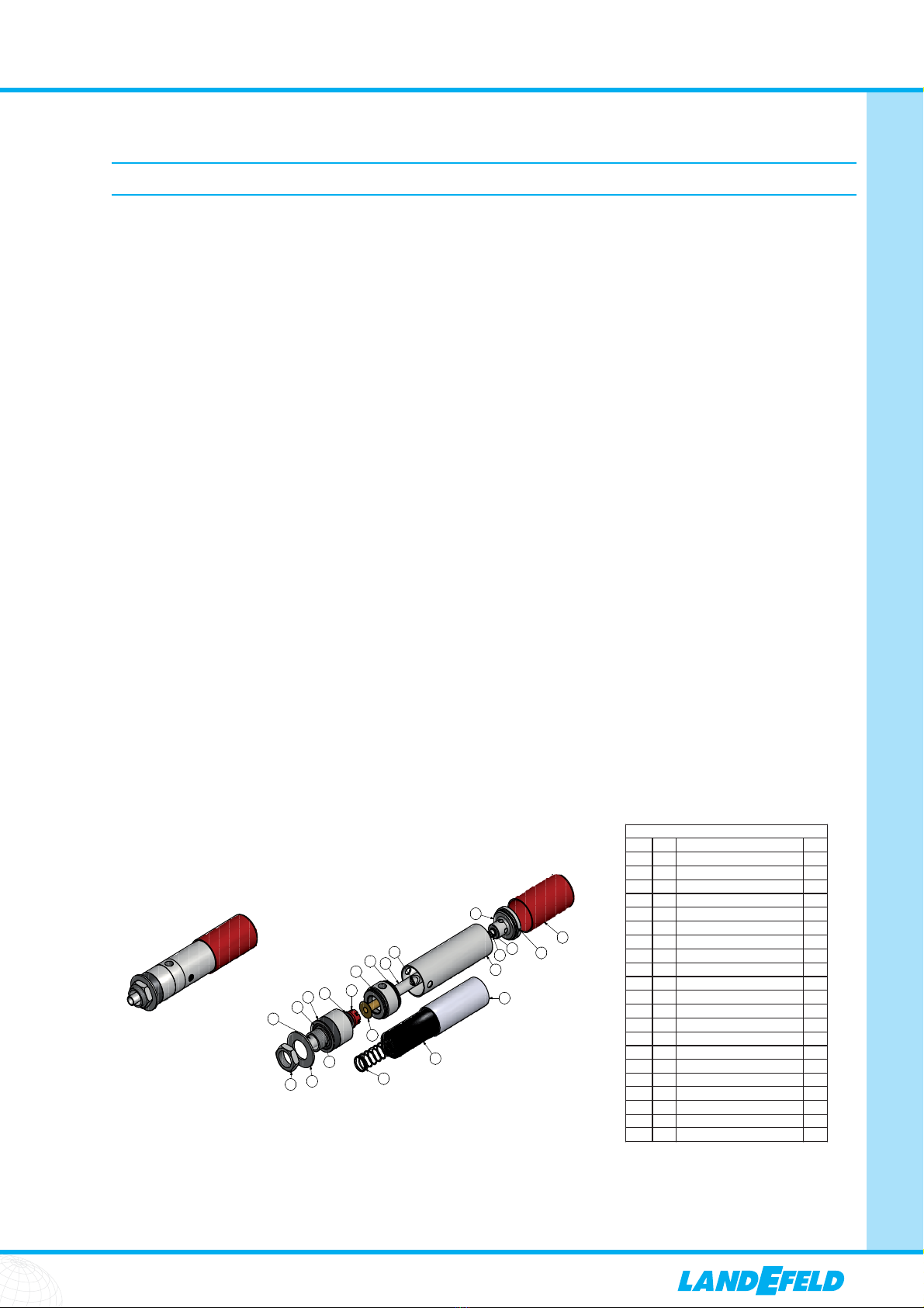
7. Teileliste . . . . . . . . . . . . . . . . . . . . . . . . . . . . . . . . . . . . . . . . . . . . . . . . . . . . . . . . . . . . . . . . . . . . . . . . . . . . . . . . . . . . . . . . . . . . . . . . . . . . . . . . . . .3
8. Abmessungen . . . . . . . . . . . . . . . . . . . . . . . . . . . . . . . . . . . . . . . . . . . . . . . . . . . . . . . . . . . . . . . . . . . . . . . . . . . . . . . . . . . . . . . . . . . . . . . . . . . . . . .3
8.1. VORTEX 14 B . . . . . . . . . . . . . . . . . . . . . . . . . . . . . . . . . . . . . . . . . . . . . . . . . . . . . . . . . . . . . . . . . . . . . . . . . . . . . . . . . . . . . . . . . . . . . . . . . . . .3
8.2. VORTEX 14 KB . . . . . . . . . . . . . . . . . . . . . . . . . . . . . . . . . . . . . . . . . . . . . . . . . . . . . . . . . . . . . . . . . . . . . . . . . . . . . . . . . . . . . . . . . . . . . . . . . . .3
8.3. VORTEX 14 CC . . . . . . . . . . . . . . . . . . . . . . . . . . . . . . . . . . . . . . . . . . . . . . . . . . . . . . . . . . . . . . . . . . . . . . . . . . . . . . . . . . . . . . . . . . . . . . . . . .3
9. Bedienungsanleitung VORTEX 14 KP . . . . . . . . . . . . . . . . . . . . . . . . . . . . . . . . . . . . . . . . . . . . . . . . . . . . . . . . . . . . . . . . . . . . . . . . . . . . . . . . . . . . . . .4
10. Bedienungsanleitung VORTEX 14 CC . . . . . . . . . . . . . . . . . . . . . . . . . . . . . . . . . . . . . . . . . . . . . . . . . . . . . . . . . . . . . . . . . . . . . . . . . . . . . . . . . . . . . .8
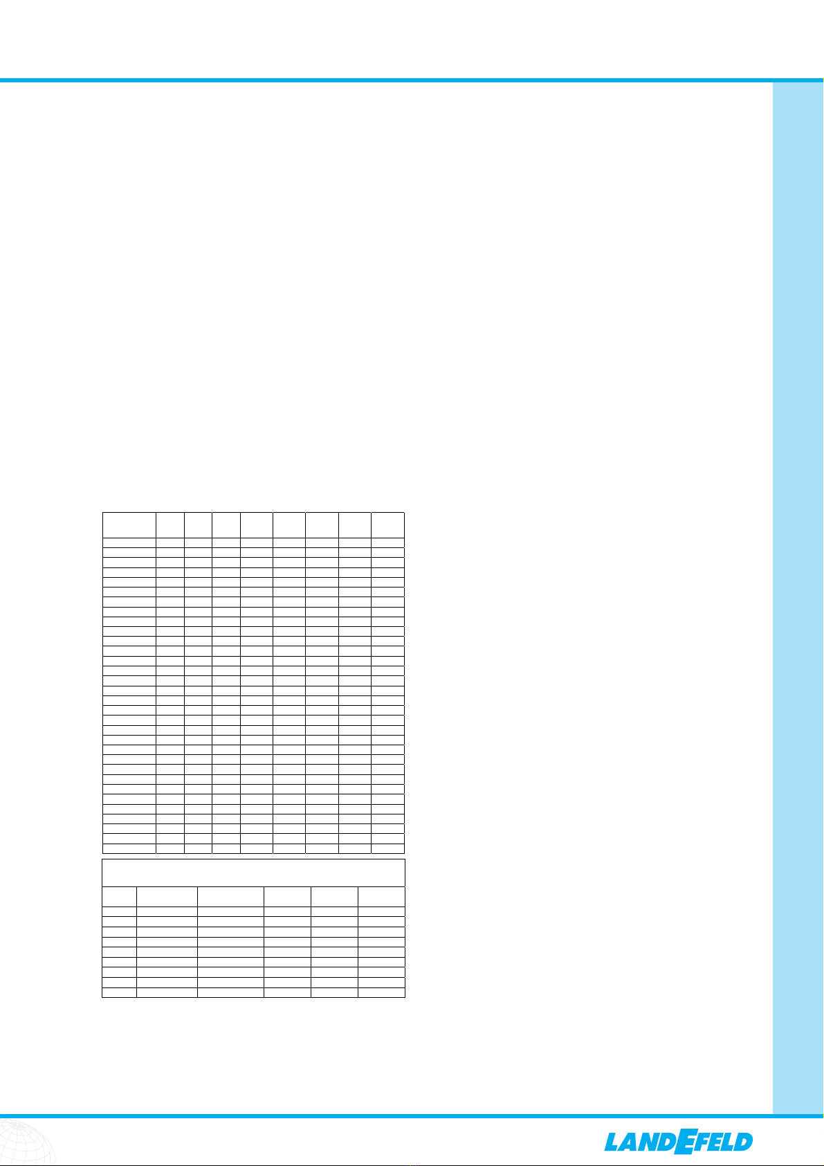
2. Artikelnummern und Daten
3. Sicherheitshinweis
Achtung: Das VORTEX-Rohr erzeugt sowohl kalte als auch heiße Luft. Teile des Rohres werden im
Betrieb heiß/kalt und sollten nicht berührt werden.
Luft- Kaltluft- Bau-
Typ eintritt austritt länge Rohr-Ø Lieferumfang
VORTEX 14 B Rp 1/4“ IG G 1/4“ AG 210 45 VORTEX-Rohr mit rotem Generator
VORTEX 14 Rp 1/4“ IG G 1/2“ IG 285 45 VORTEX-Rohr mit Schalldämpfer (für Kaltluft-
seite), 8 Stk. VORTEX-Generatoren (gelb, grün,
rot, weiß, blau, grau, beige), Gelenkschlauch
für Kaltluft
VORTEX 14 KP Rp 1/4“ IG G 1/2“ IG 285 45 VORTEX-Rohr mit Schalldämpfer (für Kalt- und
Warmluftseite), 4 Stk. VORTEX-Generatoren
(gelb, rot, blau, braun), Gelenkschlauch für
Kaltluft, Magnetfuß
VORTEX 14 CC ** Rp 1/4“ IG Gehäuse- 200 45 VORTEX-Rohr zur Schaltschrankkühlung (max.
befestigung 1800x1800x600), Thermostatsteuerung, 4 Stk.
in 3/4“-Loch, VORTEX-Generatoren (gelb, rot, blau, braun),
Luftverteilung Abluftventil in VORTEX-Rohr integriert, Schlauch
durch Schlauch zur Luftverteilung, ausgeführt nach IP 56
** bitte gewünschte Spannung angeben
VORTEX-Rohre - druckluftbetriebene Kältegeneratoren
Funktion: Einströmende Druckluft wird durch das VORTEX-Rohr in einen Warmluft- und einen Kaltluftstrom aufgeteilt.
Die warme Luft tritt auf der einen, die kalte Luft auf der anderen Seite des Rohres aus. Durch ein Regulierventil lässt sich
die Temperaturdifferenz zwischen eintretender Druckluft und austretender Kaltluft einstellen. Bei sinkender
Austrittstemperatur verringert sich gleichzeitig die austretende Kaltluftmenge. Es lassen sich Temperaturen von -40°C auf
der Kaltluft- und bis zu +110°C auf der Heißluftseite erzeugen. Bei konstanter Lufteintrittstemperatur und Druck kann
die Austrittstemperatur mit einer Toleranz von +/- 0,6 K eingestellt werden.
Werkstoffe: Gehäuse: Edelstahl AISI 303, VORTEX-Generator: Kunststoff
Temperaturbereich: -20°C bis max. +120°C
Betriebsdruck: 1 - 8 bar, optimal: 5 bar (gefilterte, ungeölte Druckluft)
Anwendungsbeispiele: Ÿgenaue Temperaturregelung
Ÿgenaue Anpassung des VORTEX-Rohres an jede Anforderung durch mitgelieferte leicht
wechselbare VORTEX-Generatoren
ŸKühlung von Lötstellen, Heißkleber oder Klebstoffen
ŸKühlung beim Punktschweißen, vermeidet Verfärbungen und Verformungen
ŸKühlung von z. B. flüssiger Schokolade in der Lebensmittelverarbeitung
ŸKühlung von Kaltform- und Ultraschallwerkzeugen
ŸKühlung bei spanabhebender Bearbeitung ohne Kühlmittel (z. B. für Kunststoffe)
ŸKühlung von Nadeln in Nähmaschinen
ŸKühlung von Schneidwerkzeugen
ŸThermo-Prüfung elektronischer Komponenten
ŸSchrumpfpassungen
orteile: Ÿgeringe Anschaffungs- und Betriebskosten
Ÿwartungsfrei
Ÿkeine beweglichen Bauteile - kein Verschleiß
ü
Farbe gelb grün rot*** weiß blau grau beige braun
Temperatur* -31C° -33C° -30C° -34C° -26C° -30C° -24C° -29C°
Kälteleistung* (kcal/h) 130 130 230 230 380 380 630 630
Luftverbrauch* (l/min) 280 280 420 420 700 700 990 990
* Lufteintritt bei 5,5 bar und 20°C, Regelungsschraube 2,5 Umdrehungen geöffnet (70% des Luftstrahls entweicht als Kaltluft)
*** als Standard in allen VORTEX-Rohren eingebaut
VORTEX-Generatoren
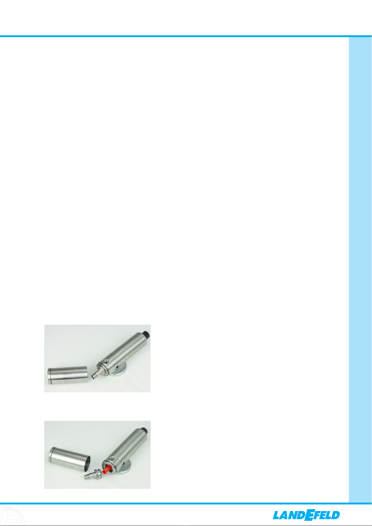
Typ VORTEX 14 B
Typ VORTEX 14 KP
Typ VORTEX 14 CC
Kälteerzeugung mit Druckluft!
Ÿfür den Betrieb wird nur Druckluft benötigt,
keine Elektrizität
Ÿkeine Rückstände auf dem gekühltem Gut
durch Kühlmittel oder Kältespray
Typ VORTEX 14