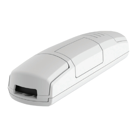
L&L TLR04M-350-500 User manual

1/8
L&L Luce&Light srl / Via Trescalini, 5 / 36031 Dueville, Vicenza / Italy / T +39 0444 36 05 71 / F +39 0444 59 43 04
TLR04M-350-500
+DAECTLR04M-350-500
rev. 02 30/11/2022
B10
Made in Italy
Power supply units and control gear /Alimentatori ed elettronica di controllo
IP20
12 ÷ 36 Vdc - 433.92 MHz
TLR04M-350-500
CONTROL UNIT FOR RGB LED FIXTURES IN COSTANT CURRENT 350-500 mA (JUMPER SETTING).
POWER SUPPLY IN 12-36VDC. RX RADIO 433 MHZ, 3 PUSH N.O. INPUTS, EXTENDER CONNECTOR AVAILABLE.
TECHNICAL DATA
Power supply 12-36 Vdc
Output 3 channels (@ 350/500 mA)
Type of load RGB LED with constant current
N° of programmable transmitters 30
Radio frequency 433.920MHz ISM
IP rate IP20
Working temperature -20°C — +55°C
Dimensions 174x46x35 mm
WARNINGS
• Installation must be carried out only by qualied technicians in compliance with the electrical and safetystandards in force.
• All connections must be made with the power turned o.
• Use suitable cables.
• Do not cut through the aerial.
• A suitably sized disconnection device must be set up on the electric power line that supplies the product.
• Disposal of waste materials must fully respect local standards.
INSTALLATION INSTRUCTIONS TLR04M-350-500

2/8
L&L Luce&Light srl / Via Trescalini, 5 / 36031 Dueville, Vicenza / Italy / T +39 0444 36 05 71 / F +39 0444 59 43 04
TLR04M-350-500
INPUT3: P3
INPUT2: P2
INPUT1: P1
LN
L: Brown
N: Blue
+Red
- Black
POWER SUPPLY
OUTPUT: 12V/24V/36V
+
P1
P2
P3
C
-+-+--+
BGR
7891011121314
123456
CONNECTION DIAGRAM
Loads with constant
current
(choose a load that’s
compatible with the
power supply in terms
of power).
12 to 36 Vdc
power supply
(choose a power supply
compatible with the load
to be controlled in terms
of voltage and power).
! =
Terminals 3-4-5 are reserved for devices with
buttons (see page 4 for operation).
INSTALLATION INSTRUCTIONS TLR04M-350-500
EXTENDER
(accessory
module)
OUT3
BLUE LED
AERIAL AERIAL
POWER SUPPLY
OUT2
GREEN LED
OUT1
RED LED
Note: multiple buttons or loads can be connected by using parallel cabling.

3/8
L&L Luce&Light srl / Via Trescalini, 5 / 36031 Dueville, Vicenza / Italy / T +39 0444 36 05 71 / F +39 0444 59 43 04
TLR04M-350-500
OUT1OUT2OUT3
SET THE OUTPUT CURRENT
With the jumper is possible to set the current provided to the Leds.
The selection is dierent for each out:
JUMPER INSERTED=
500mA
JUMPER NOT INSERTED=
350mA
INSTALLATION INSTRUCTIONS TLR04M-350-500

4/8
L&L Luce&Light srl / Via Trescalini, 5 / 36031 Dueville, Vicenza / Italy / T +39 0444 36 05 71 / F +39 0444 59 43 04
TLR04M-350-500
PUSH N.O. USAGE
FIXTURES
OFF
FIXTURES
ON
INPUT P1:
short pressure On O
INPUT P1:
long pressure Dimmer up Dimmer up / Dimmer down
INPUT P2:
short pressure no actions
Color change refered to a memorized palette (white, light
yellow, light green, dark green, light blue, blue, violet, light
violet, pink, red, orange, light orange, yellow)
INPUT P2:
long pressure Color dene: choose of the color viewing all gamma of RGB Memorization of the state at the desired setup
INPUT P3:
short pressure no actions
Play / stop “color cycle”
Every short press:
1 ash= play “color cycle”
2 ashes= stop “color cycle”
INPUT P3:
long pressure no actions
Setup “color cycle” duration
Every long press:
1 ash= “color cycle” of 90 sec
2 ashes= “color cycle” of 15 min
INSTALLATION INSTRUCTIONS TLR04M-350-500

5/8
L&L Luce&Light srl / Via Trescalini, 5 / 36031 Dueville, Vicenza / Italy / T +39 0444 36 05 71 / F +39 0444 59 43 04
TLR04M-350-500
RADIO PROGRAMMING
PROCEDURE:
STEP 1
Short press on the “SET” key let you
scroll through the menu until “P1” pro-
gramming appears on the display.
SHORT
PRESSURE
STEP 2
A prolonged press on the “SET” key
(approx. 3 seconds) takes you into pro-
gramming.
The LED on the receiver comes on.
LONG
PRESSURE
STEP 3
Short press on key “B” let you set value
“1” on the display.
SHORT
PRESSURE
STEP 4
Give a long press on key “B” (approx.
3 seconds).
The LED on the display comes on.
LONG
PRESSURE
STEP 5
Make a transmission with the transmitter to be saved (see trans-
mitter manual, the paragraph entitled “transmitter programming”).
The LED on the receiver ashes 3 times to signal that it has been
received.
MAKE A TRANSMISSION
WITH THE TRANSMITTER
THE LED
FLASHES 3 TIMES
STEP 6
The control unit listens for 50 seconds
in case you want to add other transmit-
ters.
To immediately exit the procedure give
a short pressure on key “b”.
The LED on the display turns o.
SHORT
PRESSURE
STEP 7
The control unit goes back to the menu displaying the radio pro-
gramming. If you want to save other transmitters, go back to
point 3 of this procedure.
If you want to go back to the menu displaying the dierent types
of programming, give a prolonged press to the “SET” key (ap-
prox. 3 seconds).
INSTALLATION INSTRUCTIONS TLR04M-350-500

6/8
L&L Luce&Light srl / Via Trescalini, 5 / 36031 Dueville, Vicenza / Italy / T +39 0444 36 05 71 / F +39 0444 59 43 04
TLR04M-350-500
LOAD STATE WHEN THE CONTROL UNIT IS SWITCHED ON
Default: Light O
This process is used to set the state of Leds when the control unit is switched on (for example when the power supply is provided by a general
switch or timer).
PROCEDURE:
STEP 1
Short press on the “SET” key let you
scroll through the menu until “P6” pro-
gramming appears on the display.
SHORT
PRESSURE
STEP 2
A prolonged press on the “SET” key
(approx. 3 seconds) takes you into pro-
gramming.
The LED on the receiver lights up.
LONG
PRESSURE
STEP 3
Short presses on key “B” let you
choose the function you want to pro-
gram shown on the displays based on
what is shown in the table alongside.
DISPLAY BRIGHTNESS AT SWITCH-ON
1 Default (light o)
2 The light switches on in the same status as the load is cur-
rently in: set the desired status of light.
SHORT
PRESSURE
STEP 4
To conrm give a prolonged press on
the “SET” key (approx. 3 seconds).
LONG
PRESSURE
STEP 5
The control unit goes back to the menu
displaying the dierent types of pro-
gramming.
INSTALLATION INSTRUCTIONS TLR04M-350-500

7/8
L&L Luce&Light srl / Via Trescalini, 5 / 36031 Dueville, Vicenza / Italy / T +39 0444 36 05 71 / F +39 0444 59 43 04
TLR04M-350-500
FACTORY SETTING, RESET
This procedure let you take the control unit back to factory settings.
PROCEDURE:
STEP 1
Short presses on the “SET” key let you
scroll through the menu until “FS” pro-
gramming appears on the display.
SHORT
PRESSURE
STEP 2
A prolonged press on the “SET” key
(approx. 3 seconds) takes you into pro-
gramming.
The LED on the receiver lights up.
LONG
PRESSURE
STEP 3
Short presses on the “B” key, let you modify the setup that appears in display “b”:
display = F1 reset factory parameters, but no deletion of already programmed transmitters;
display = F2 full reset of factory parameters, even stored transmitters will be deleted.
SHORT
PRESSURE
STEP 4
To conrm, give a prolonged press on
the “SET” key (approx. 3 seconds).
The LED ashes.
LONG
PRESSURE
STEP 5
The control unit goes back to the menu
displaying the dierent types of pro-
gramming.
INSTALLATION INSTRUCTIONS TLR04M-350-500

1/8
L&L Luce&Light srl / Via Trescalini, 5 / 36031 Dueville, Vicenza / Italy / T +39 0444 36 05 71 / F +39 0444 59 43 04
TLR04M-350-500
+DAECTLR04M-350-500
rev. 02 30/11/2022
B10
Made in Italy
Power supply units and control gear /Alimentatori ed elettronica di controllo
IP20
12 ÷ 36 Vdc - 433.92 MHz
ISTRUZIONI DI INSTALLAZIONE TLR04M 350-500
TLR04M-350-500
CENTRALE DI COMANDO PER LED RGB IN CORRENTE COSTANTE 350-500 mA (JUMPER SU OGNI USCITA).
ALIMENTAZIONE 12-36Vdc. RX RADIO 433.920 MHz, 3 INGRESSI FILARI, INGRESSO PER EXTENDER.
DATI TECNICI
Alimentazione 12-36 Vdc
Uscita 3 canali (@350/500mA)
Tipo di carico LED RGB in corrente costante
N° trasmettitori programmabili 30
Frequanza radio 433.920MHz ISM
Grado di protezione IP20
Temperatura di funzionamento -20°C ÷ +55°C
Dimensioni 174x46x35 mm
AVVERTENZE
• L’installazione deve essere eseguita esclusivamente da personale tecnico qualicato nel rispetto delle normative elettriche e delle norme
di sicurezza vigenti.
• Tutti i collegamenti devono essere eseguiti in assenza di tensione elettrica.
• Servirsi di cavi adeguati.
• Non tagliare l’antenna (vedi gura 1.1b).
• Prevedere, nella linea elettrica che alimenta il prodotto, un dispositivo di disconnessione opportunamente dimensionato.
• Smaltire i materiali di riuto nel pieno rispetto della normativa locale.
• Non superare i limiti di carico indicati e utilizzare alimentatori correttamente dimensionati con il carico e protetti.

2/8
L&L Luce&Light srl / Via Trescalini, 5 / 36031 Dueville, Vicenza / Italy / T +39 0444 36 05 71 / F +39 0444 59 43 04
TLR04M-350-500
INPUT3: P3
INPUT2: P2
INPUT1: P1
LN
L: Brown
N: Blue
+Red
- Black
POWER SUPPLY
OUTPUT: 12V/24V/36V
+
P1
P2
P3
C
-+-+--+
BGR
7891011121314
123456
ISTRUZIONI DI INSTALLAZIONE TLR04M-350-500
SCHEMA DI COLLEGAMENTO
Carichi a corrente
costante
(scegliere un il carico
compatibile con l’ali-
mentatore in termini di
tensione e potenza).
Alimentatore
da 12 a 36 Vdc
(scegliere un alimentato-
re compatibile con il cari-
co da pilotare in termini di
tensione e potenza).
! =
I morsetti 3-4-5 sono dedicati a dispositivi di
tipo pulsante (vedi pag 4 per il funzionamento).
EXTENDER
(modulo
accessorio)
OUT3
LED BLU
ANTENNA ANTENNA
ALIMENTAZIONE
OUT2
LED VERDE
OUT1
LED ROSSO
ATTENZIONE: si possono collegare più pulsanti o carichi cablandoli in parallelo.

3/8
L&L Luce&Light srl / Via Trescalini, 5 / 36031 Dueville, Vicenza / Italy / T +39 0444 36 05 71 / F +39 0444 59 43 04
TLR04M-350-500
OUT1OUT2OUT3
ISTRUZIONI DI INSTALLAZIONE TLR04M-350-500
SELEZIONE DELLA CORRENTE IN USCITA
Con i jumper in scheda è possibile selezionare la corrente con la quale la centrale alimenta il carico.
La selezione può essere fatta per ogni uscita separatamente:
JUMPER INSERITO=
500mA
JUMPER NON INSERITO=
350mA

4/8
L&L Luce&Light srl / Via Trescalini, 5 / 36031 Dueville, Vicenza / Italy / T +39 0444 36 05 71 / F +39 0444 59 43 04
TLR04M-350-500
ISTRUZIONI DI INSTALLAZIONE TLR04M-350-500
UTILIZZO VIA INPUT PULSANTE NA
CARICO
SPENTO
CARICO
ACCESO
INGRESSO P1:
pressione breve On del carico O del carico
INGRESSO P1:
pressione lunga Dimmer up intensità Dimmer up intensità / Dimmer down intensità
INGRESSO P2:
pressione breve Nessuna azione
Cambio del colore (bianco, giallo chiaro, verde chiaro, ver-
de scuro, azzurro, blu, viola, viola chiaro, rosa, rosso, aran-
cione, arancione chiaro, giallo)
INGRESSO P2:
pressione lunga
Dimmer colore: mi muovo gradatamente tra tutti i colori, al
rilascio del tasto il carico si ferma sul colore visualizzato Memorizzo il colore e l’intensità su cui è impostato il carico
INGRESSO P3:
pressione breve Nessuna azione
Play / stop “ciclo colore”
Ad ogni pressione prolungata del tasto il carico emetterà:
1 lampeggio= play “ciclo colore”
2 lampeggi= stop “ciclo colore”
INGRESSO P3:
pressione lunga Nessuna azione
Regolazione durata “ciclo colore”
Ad ogni pressione prolungata del tasto il carico emetterà:
1 lampeggio= “ciclo colore” di 90 secondi
2 lampeggi= “ciclo colore” di 15 minuti

5/8
L&L Luce&Light srl / Via Trescalini, 5 / 36031 Dueville, Vicenza / Italy / T +39 0444 36 05 71 / F +39 0444 59 43 04
TLR04M-350-500
PROGRAMMAZIONE RADIO
PROCEDURA:
ISTRUZIONI DI INSTALLAZIONE TLR04M-350-500
PASSO 1
Con pressioni brevi del tasto “SET”
scorrere il menù no a visualizzare sul
display la programmazione “P1”.
PRESSIONE
BREVE
PASSO 2
Fare una pressione prolungata del ta-
sto “SET” (circa 3s) per entrare nella
programmazione.
Il led sulla ricevente si accende.
PRESSIONE
LUNGA
PASSO 3
Con pressioni brevi del tasto “B” impo-
stare il valore “1” sul display.
PRESSIONE
BREVE
PASSO 4
Fare una pressione prolungata del ta-
sto “B” (circa 3s).
Il led sul display si accende.
PRESSIONE
LUNGA
PASSO 5
Fare una trasmissione con il trasmettitore da memorizzare (vedi
manuale del trasmettitore, paragrafo “programmazione del tra-
smettitore”).
Il led sulla ricevente emette tre lampeggi e si riaccende sso.
INVIO DI UN COMANDO
CON IL TRASMETTITORE
LED FA
3 LAMPEGGI
PASSO 6
La centrale resta in ascolto per 50 se-
condi.
Per uscire immediatamente dalla pro-
cedura fare una pressione breve del
tasto “b”.
Il led sul display si spegne.
PRESSIONE
BREVE
PASSO 7
Nel display si torna al menu di “programmazione radio”.
Se si vogliono memorizzare altri trasmettitori, ritornare al punto 3
di questa procedura.
Se si vuole tornare al menù di visualizzazione delle programma-
zioni fare una pressione prolungata (circa 3 sec) del tasto “SET”.

6/8
L&L Luce&Light srl / Via Trescalini, 5 / 36031 Dueville, Vicenza / Italy / T +39 0444 36 05 71 / F +39 0444 59 43 04
TLR04M-350-500
ISTRUZIONI DI INSTALLAZIONE TLR04M-350-500
STATO DELLA LUCE ALL’ALIMENTAZIONE DELLA CENTRALE
Default: Luce spenta
Con questa procedura si imposta lo stato della luce quando la centralina viene alimentata (utile ad esempio se la centrale è alimentata da un
interruttore generale o da un orologio a monte).
PROCEDURA:
PASSO 1
Con pressioni brevi del tasto “SET”
scorrere il menù no a visualizzare sul
display la programmazione “P6”.
PRESSIONE
BREVE
PASSO 2
Fare una pressione prolungata del ta-
sto “SET” (circa 3s) per entrare nella
programmazione.
Il led sulla ricevente si accende.
PRESSIONE
LUNGA
PASSO 3
Con pressioni brevi del tasto “B” sce-
gliere la funzione che si vuole program-
mare visualizzata sul display in base
alle indicazioni della tabella a lato.
DISPLAY LUMINOSITÀ ALL’ACCENSIONE
1 Default (luce spenta)
2 Accensione della luce pari allo stato in cui si trova il carico
attualmente: impostare la luce desiderata.
PRESSIONE
BREVE
PASSO 4
Per confermare fare una pressione pro-
lungata del tasto “SET” (circa 3s).
PRESSIONE
LUNGA
PASSO 5
Nel display si torna al menu di “visualiz-
zazione delle programmazioni”.

7/8
L&L Luce&Light srl / Via Trescalini, 5 / 36031 Dueville, Vicenza / Italy / T +39 0444 36 05 71 / F +39 0444 59 43 04
TLR04M-350-500
ISTRUZIONI DI INSTALLAZIONE TLR04M-350-500
IMPOSTAZIONI DI FABBRICA, RESET DELLA CENTRALE
Con questa procedura è possibile portare la centrale alle impostazioni di fabbrica.
PROCEDURA:
PASSO 1
Con pressioni brevi del tasto “SET”
scorrere il menù no a visualizzare sul
display la programmazione “FS”.
PRESSIONE
BREVE
PASSO 2
Fare una pressione prolungata del ta-
sto “SET” (circa 3s) per entrare nella
programmazione.
Il led sulla ricevente si accende.
PRESSIONE
LUNGA
PASSO 3
Con pressioni brevi del tasto “B” posso modicare l’impostazione visualizzata sul display “b”:
display = F1 reset ai parametri di fabbrica, ma nessuna cancellazione dei trasmettitori già programmati;
display = F2 reset completo ai parametri di fabbrica, anche i trasmettitori memorizzati saranno cancellati.
PRESSIONE
BREVE
PASSO 4
Per confermare fare una pressione pro-
lungata del tasto “SET” (circa 3s).
Il led fa dei lampeggi.
PRESSIONE
LUNGA
PASSO 5
Nel display si torna al menu di “visualiz-
zazione delle programmazioni”.
Table of contents
Languages:
Other L&L Control Unit manuals


