manuals.online logo
Brands
  1. Home
  2. •
  3. Brands
  4. •
  5. ZURN
  6. •
  7. Control Unit
  8. •
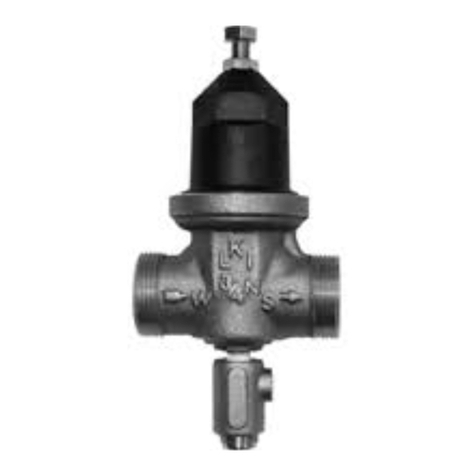
  9. ZURN WILKANS PV-PRD User manual

ZURN WILKANS PV-PRD User manual

WILKINS, a ZURN company
1747 Commerce Way, Paso Robles, CA 93446 Phone:805-238-7100 Fax:805-238-5766
Model PV-PRD
Pressure Reducing Valve
a company
®
®
The PV-PRD Pressure Reducing Valve may be installed
in any position. There is one inlet port and two outlets, for
either straight or angled installation. A ow arrow is marked
on the body and should be oriented as needed.
DISASSEMBLY
Prior to disassembly, relieve all pressure in pilot system
and then remove the PV-PRD.
1. Secure valve body and remove main cap on bottom
of valve using an adjustable wrench.
2. Use a 13 mm socket to remove the plunger.
3. Next remove adjustment cover (plastic cover), 3/8”
adjustment bolt with nut, 8 socket head screws
around the pilot bell using a 5/32" hex key, spring,
and spring disc.
4. At this point the PRV stem yoke is free to move and
can be removed from the valve body.
5. Continue to remove the 5/16" diaphragm nut, lock
washer, and diaphragm retainer.
6. After completely disassembling, thoroughly clean and
inspect all components before reassembly. Replace
any parts as necessary after inspection.
7. The pilot seat generally does not need to be removed,
but it can be removed with a 1/2" socket, if required.
REASSEMBLY
Reassembly of the PV-PRD is the reverse of disassembly.
1. Install the new o-ring on top of pilot yoke threads follo-
wed by new diaphragm and diaphragm disc.
Then place lock washer over pilot yoke stem along
with the 5/16" diaphragm nut and tighten. Diaphragm
bolt holes must be centered on yoke legs.
See following diagram:
3. Then attach plunger to the bottom of the pilot yoke via
the main cap hole and tighten with a 13 mm socket.
4. Install main cap in bottom of valve body with new
o-ring.
5. Install spring, spring disc, and pilot bell on the valve
body.
6. Insert socket head cap screws into pilot bell holes
and thread into valve body. Tighten all screws in a
cross pattern.
7. Install adjusting screw by hand with jam nut. Set valve
once reinstalled into main valve pilot system.
8. While owing water as shown in Table 1, adjust the
Wilkins PV-PRD control to desired pressure if installed
on an ACV. To change pressure setting, turn the
adjusting screw clockwise to increase pressure,
counterclockwise to decrease pressure. There must
be liquid owing through the valve during pressure
adjustments. When the desired setting has been
made, tighten jam nut.
9. For further assistance or ordering replacement parts go
to www.zurn.com or call product support 877-222-5356.
Table 1
YOKE LEGS
CENTER YOKE LEGS
BETWEEN
DIAPHRAGM HOLES
2. Next carefully slide yoke assembly into body and
around pilot seat.
NOTE: Line up diaphragm screw holes with holes
in body. Move yoke up and down checking for yoke
contacting or dragging on valve body.
VALVE
SIZE
inches 2 1/2 3 4 6
mm 65 80 100 150
MINIMUM FLOW RATES TO SET VALVE (GPM)35 60 100 220
MAX. FLOW RATE (GPM) 375 600 1000 2250
ITEM DESCRIPTION
1 3/8" PRV-PILOT BODY, LEAD FREE BRASS
2 PLUNGER, SS W/BUNA NITRILE 90 SHORE
3 MAIN CAP, LEAD FREE BRASS
4 ADJUSTMENT COVER
5 3/8"-16 ADJUSTMENT BOLT, BRASS
6 3/8" PILOT SEAT, SS
7 20-200 PSI SPRING, CHROME SILICON
8 DIAPHRAGM DISC, SS
9 SPRING DISC, SS
10 PILOT BELL, BRASS
11 O-RING, BUNA NITRILE NSF LISTED
12 5/16"-18 DIAPHRAGM NUT, SS
13 10-32X5/8 SOCKET HEAD CAP SCREW
14 DIAPHRAGM NYLON REINFORCED BUNA NITRILE
15 PRV STEM YOKE, SS
16 3/8"-16 JAM HEX NUT, SS
17 5/16" INTERNAL TOOTH LOCK WASHER, SS
18 O-RING, BUNA NITRILE NSF LISTED
19 UL TAG RED, BRASS
18
12
14
17
15
8
6
1
2
7
10
3
13
11
5
4
16
9
Maintenance Instructions
Maintenance Instructions Installation Troubleshooting
a company
®
®
Troubleshooting
WILKINS, a ZURN company
1747 Commerce Way, Paso Robles, CA 93446 Phone:805-238-7100 Fax:805-238-5766
a company
®
®
Proposition 65 Warning This product contains chemicals known to the State of California to cause cancer or birth defects
or other reproductive harm.
WARRANTY: WILKINS Valves are guaranteed against defects of material or workmanship when used for the services recommended. If in any
recommended service, a defect develops due to material or workmanship, and the device is returned, freight prepaid, to WILKINS within 12 months
from date of purchase, it will be repaired or replaced free of charge. WILKINS’ liability shall be limited to our agreement to repair or replace the
valve only.
NOTICE: Annual inspection and maintenance is required of all plumbing system components. To ensure proper perfor-
mance and maximum life, this product must be subject to regular inspection, testing and cleaning.
PROBLEM POSSIBLE CAUSES CORRECTIVE ACTION
1. Outlet pressure is above
set pressure
1. The spring is over compressed 1. Loosen the adjusting screw
2. Foreign matter obstruction 2. Disassemble and remove obstruction, replace parts as
necessary
3. Cut, worn or chipped plunger seal or seat. 3. Replace with new plunger or seat.
4. Damaged diaphragm or stem o-ring 4. Disassemble and replace diaphragm or o-ring
5. Yoke dragging on body 5. Disassemble valve. Check yoke placement per
Reassembly Step 2 and reassemble
2. Outlet pressure is below
set pressure
1. Weak or no spring compression 1. Turn adjusting screw in to increase pressure regulation
2. Spring damaged 2. Disassemble and replace spring as needed
3. Spring disc out of place 3. Disassemble and replace or adjust spring disc as
needed
4. Yoke dragging on body 4. Disassemble valve. Check yoke placement per
Reassembly Step 2 and reassemble
5. Foreign matter between plunger and
main cap
5. Disassemble and remove obstruction
3. Leakage from valve 1. Damaged diaphragm, yoke or main cap
o-ring
1. Disassemble and replace damaged part as needed
2. Ports not sealed 2. Remove and reinstall port ttings Teon tape or pipe
sealant
3. Loose diaphragm nut 3. Disassemble and re-tighten the diaphragm nut
ISPV-PRD (REV. 6/12)
2
Installation Instructions
Before installing the pressure reducing valve, ush out
the line to remove loose dirt and scale which might damage
the plunger and seat. Install the valve in line with the arrow
on the valve body pointing in the direction of ow. All
valves will be furnished with stock settings. To readjust
reduced pressure, loosen the outer locknut and turn the
adjustment bolt clockwise (into the bell housing) to raise
the reduced pressure, or counterclockwise (out of the
bell housing) to lower the reduced pressure. The valve
may be installed in a horizontal or vertical position.
PV-PRD SPECS:
Adjustment Range Pressure: 20-200 psi
(Flowing residual outlet pressure)
Max Inlet Pressure: 400 psi
NOTE : All adjustments should be made with a pres-
sure gauge and while owing water through the main
valve.

Other ZURN Control Unit manuals

ZURN AQUA-GARD ZW1070/15 Maintenance and service guide

ZURN

ZURN AQUA-GARD ZW1070/15 Maintenance and service guide

ZURN ZER6000AV-CPM User manual

ZURN

ZURN ZER6000AV-CPM User manual

ZURN AquaSense ZTR Series User manual

ZURN

ZURN AquaSense ZTR Series User manual

ZURN Wilkins ZW109BP Owner's manual

ZURN

ZURN Wilkins ZW109BP Owner's manual

ZURN WILKINS 450 User manual

ZURN

ZURN WILKINS 450 User manual

ZURN AquaVantage ZH Series User manual

ZURN

ZURN AquaVantage ZH Series User manual

ZURN Metroflush Z6200 series User manual

ZURN

ZURN Metroflush Z6200 series User manual

ZURN AquaSense ZER-SM Series User manual

ZURN

ZURN AquaSense ZER-SM Series User manual

ZURN AquaSense ZER-SM Series User manual

ZURN

ZURN AquaSense ZER-SM Series User manual

ZURN 350 User manual

ZURN

ZURN 350 User manual

ZURN Aquaflush Z6001 User manual

ZURN

ZURN Aquaflush Z6001 User manual

ZURN ZW215FP Installation manual

ZURN

ZURN ZW215FP Installation manual

ZURN TEMP-GARD III Z7300-SS-MT-HW-H9 User manual

ZURN

ZURN TEMP-GARD III Z7300-SS-MT-HW-H9 User manual

ZURN 350AST Series User manual

ZURN

ZURN 350AST Series User manual

ZURN QHCMKIT5 User manual

ZURN

ZURN QHCMKIT5 User manual

ZURN WILKINS BR4EC User manual

ZURN

ZURN WILKINS BR4EC User manual

ZURN AquaSense ZER-W2 Series User manual

ZURN

ZURN AquaSense ZER-W2 Series User manual

ZURN WILKINS 950LF User manual

ZURN

ZURN WILKINS 950LF User manual

ZURN TEMP-GARD Z7100 User manual

ZURN

ZURN TEMP-GARD Z7100 User manual

ZURN WILKINS ZW109FP Owner's manual

ZURN

ZURN WILKINS ZW109FP Owner's manual

ZURN LEAD-FREE ZW209 Manual

ZURN

ZURN LEAD-FREE ZW209 Manual

Popular Control Unit manuals by other brands

Omron CS1W-MCH71 - datasheet

Omron

Omron CS1W-MCH71 - datasheet

Aruba S3500 Series Uplink Module installation guide

Aruba

Aruba S3500 Series Uplink Module installation guide

Siemens ACVATIX PS53 quick start guide

Siemens

Siemens ACVATIX PS53 quick start guide

Kemper MULTI-FIX-PLUS 150 6G Installation and operating instructions

Kemper

Kemper MULTI-FIX-PLUS 150 6G Installation and operating instructions

Spirax Sarco UFT32 manual

Spirax Sarco

Spirax Sarco UFT32 manual

Orno OR-GB-426 Operating and instalation instructions

Orno

Orno OR-GB-426 Operating and instalation instructions

Kohler ENGLEFIELD K-98095X Installation and care guide

Kohler

Kohler ENGLEFIELD K-98095X Installation and care guide

Kubic CB9 manual

Kubic

Kubic CB9 manual

CALEFFI Z-one ZVR103 manual

CALEFFI

CALEFFI Z-one ZVR103 manual

Neoway Neo WM620 At command guide

Neoway

Neoway Neo WM620 At command guide

Jung KNX 5071 TSM Product documentation

Jung

Jung KNX 5071 TSM Product documentation

National Instruments SCXI-1581 user manual

National Instruments

National Instruments SCXI-1581 user manual

FrSky Neuron 60 instruction manual

FrSky

FrSky Neuron 60 instruction manual

Crestron CNTV Operation guide

Crestron

Crestron CNTV Operation guide

Hoffer Flow Controls Integrated Cryogenic Electronics HP-319 quick start guide

Hoffer Flow Controls

Hoffer Flow Controls Integrated Cryogenic Electronics HP-319 quick start guide

Allmatic BIOS2 Manual for installation

Allmatic

Allmatic BIOS2 Manual for installation

HWH 725 SERIES Operator's manual

HWH

HWH 725 SERIES Operator's manual

CALEFFI 544 Series manual

CALEFFI

CALEFFI 544 Series manual

manuals.online logo
manuals.online logoBrands
  • About & Mission
  • Contact us
  • Privacy Policy
  • Terms and Conditions

Copyright 2025 Manuals.Online. All Rights Reserved.